So far I didn’t run into any problems but I will upgrade to a 4A PSU just to be on the safe side. Without the Z-stepper and with the laser at 100% the PSU draws roughly 32W. It seems that in normal operation the Z-stepper adds another 2-3 Watts to that. So that gets awfully close to the 36W rating of the PSU.
Seems like the motor itself would turn easier than the Z axes?
How do you keep it stationary? Air hook?
Thanks for the clarification of the Z limit. No point if it’s useless to the operation.

I have yet to print the bracket for the motor. I’ll do it next week 
Actually it’s encouragement. It’s great that you are building this yourself. I wish more people could/would do this.
Take care, keep us updated…
I thought I’d make another post with a list of all the other components that I used, just in case someone wants to replicate what I did. So here goes:
*Sloppy Micro Soldering Trigger Warning*
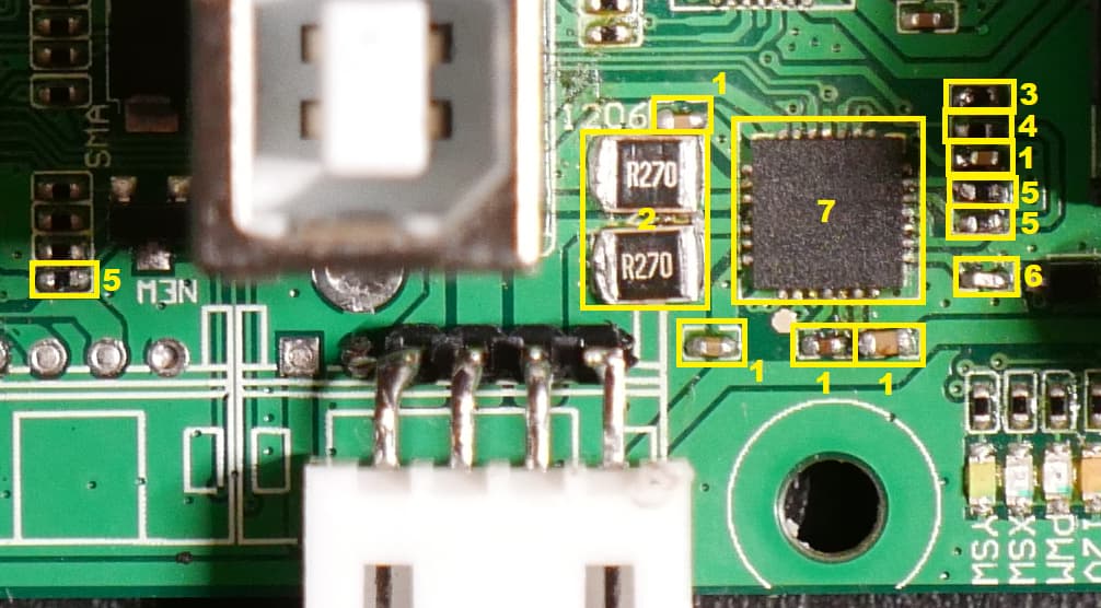
1) 0402 100nF 20VDC Capacitor
2) 1206 270mOhm Resistor (I used 1210 resistors because I didn’t have 1206 on hand. Other values are also possible, e.g. 200mOhm or 100mOhm)
3 & 4) 0402 Resistors in a Potential Divider arrangement. Eventually I settled on 3.6kOhm for 3 and 4.7kOhm for 4. That results in a Vref of 1.52V which, in combination with my sense resistors, results in 0.7A drive current. Formula: I = Vref / (8 * Rsense)
5) 0402 10kOhm Resistors
6) 0402 0.25uF 20VDC Capacitor
7) HR4988 Stepper Motor Driver (A4988 should work just as fine)
1 Like
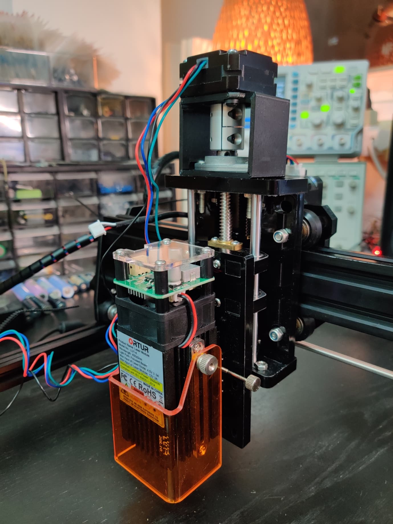
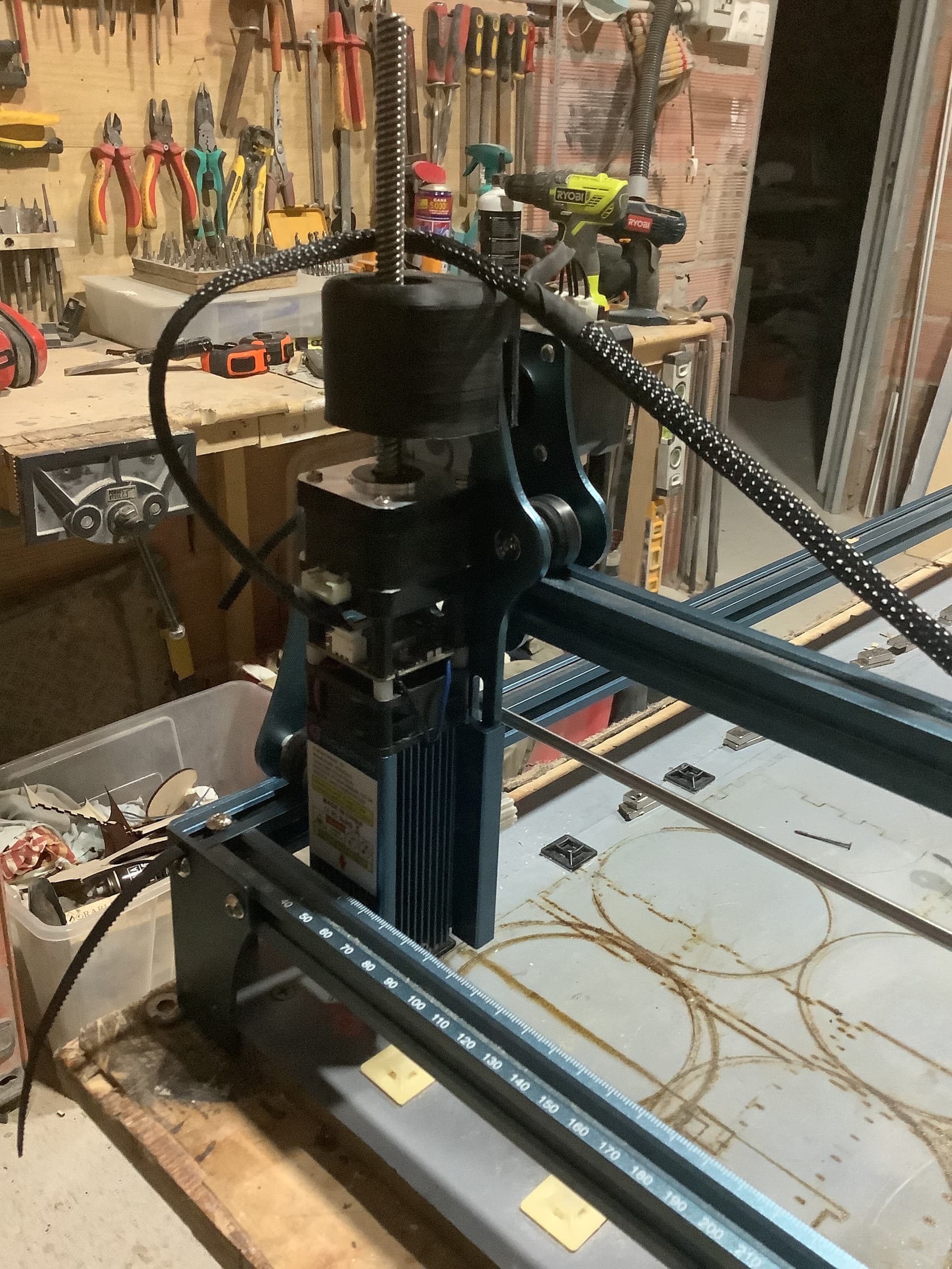
I designed and printed a bracket and here is the result:
That’s the bracket:
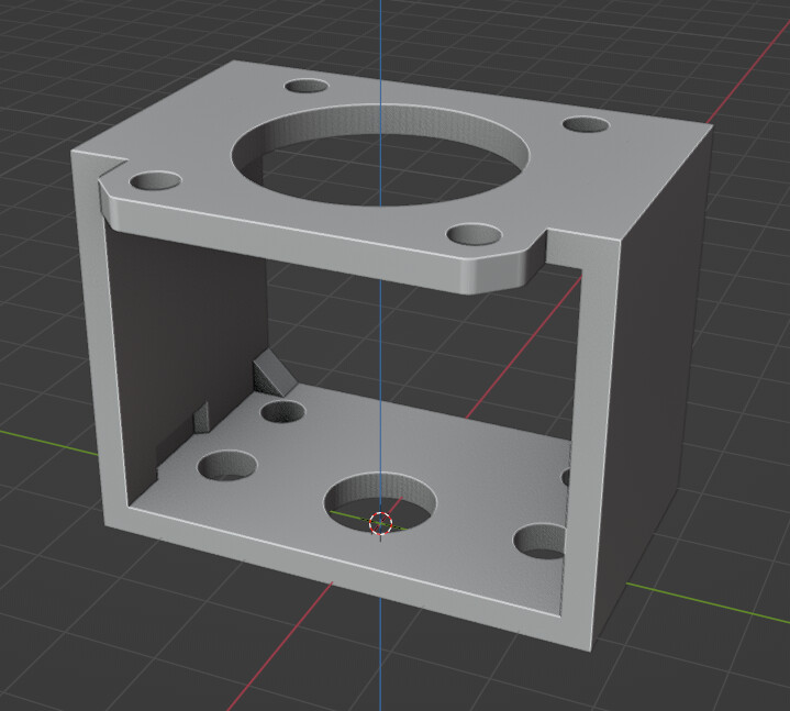
Here is the STL in case somebody want’s to print it. The file extension needs to be changed from ‘txt’ to ‘stl’:
bracket.txt (262.4 KB)
And here’s another video of everything in action:

1 Like
Video looks like it’s set to private.
Curious. Are positive Z moves going up or down?
Oops, fixed it.
Up goes up and down goes down.
I’ll be starting to look into the Firmware now and see if I can compile my own version with full Z-support.
How about for the Z-offset?
What source are you using as the base? I think there are a couple of different projects that have STM32 implementations.
Not sure what you are referring to. When I power on the machine the software-reported Z-position is always 0.00. That also means that it is necessary to disable “Soft limits ($20)”, as otherwise it wouldn’t be possible to lower the laser. Proper homing would definitely help here.
I found a couple of repos but it seems that most (all?) of them are based on GRBL 1.1f and not 1.1h. I’ll have to spend a bit more time looking into it.
I meant in terms of position. Either in cut settings:
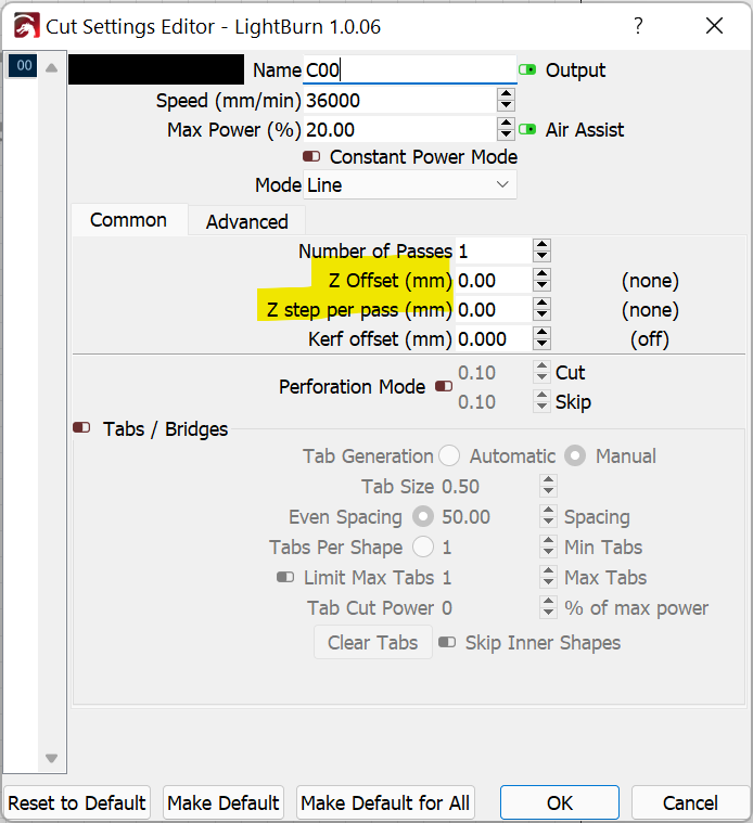
Or if you push Z-up with the move button, does “get position” Z increase or decrease in value?
Until you get it fixed, you will have to move Z to where ever you want Z to be 0, just like any other machine with no limit switches… At least you can use it…
I had one of those flexible shaft collars on my little CNC, it had terrible backlash. Ended up pitching it for a solid one.
If everything is lined up, it shouldn’t be an issue…
Good luck, keep us informed about the firmware modifications.

Oh yea, that works flawlessly. 5 passes with some extreme offset per pass:

I can imagine. Fortunately there’s nothing it has to push against here. I have tightened everything down nicely and it doesn’t budge. I didn’t get to actually cutting anything yet but I will test everything soon.
This is mine on a similar laser module (Scupfun S9). I’ve still to get Lightburn to move it yet, that’s why I’m here!
I managed to get the Z axis to move using the X or Y axis cables so not a problem with the motor or mount. I also checked my home made cable to control X motor and it worked so I went on to activate the Z axis in Lightburn and pressed the up/down icons but just get a click from the X and Y motors and no movement of Z :(.
Anyone have Sculpfun code I can have IF that’s the problem?
Does the Sculpfun S9 controller come with a port for Z-axis? Or this is something you hacked?
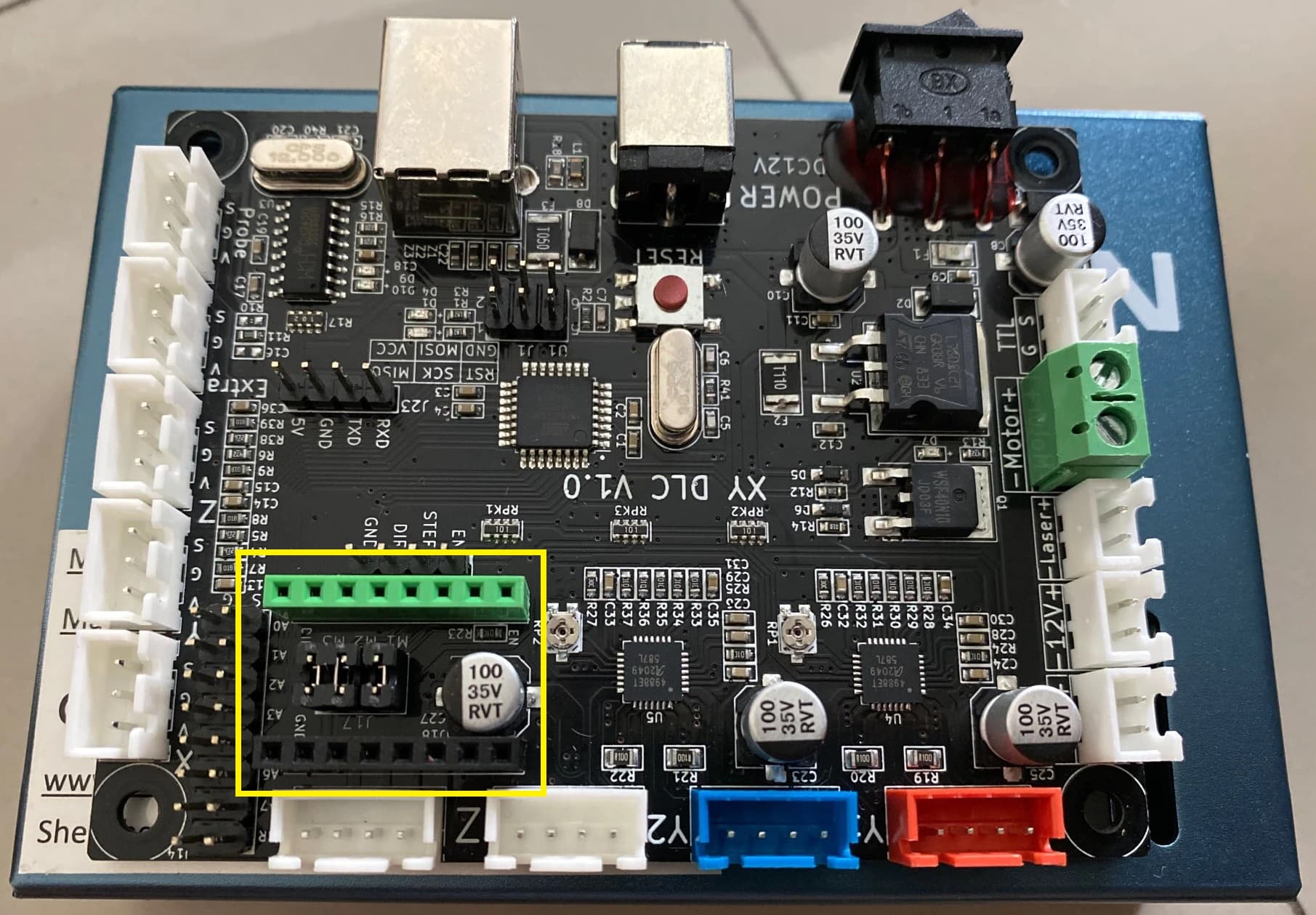
I don’t know anything about the Sculpfun S9 but after looking at a few pictures of the mainboard, it looks to me as if there are only two stepper drivers on it (for X and Y). There is, however, space for a additional stepper driver module, such as this one here: https://www.aliexpress.com/item/4000287103822.html
With this module installed you might be able to control the Z-axis.
Nice find.
I didn’t realize that the Sculpfun S9 is using a generic board. Or a lightly modified board. This looks like a slightly optimized MKS DLC with integrated stepper drivers.
Lots of interesting things on the board including ports meant for CNC operation and a probe. The serial headers are a nice touch and could be used to convert this to wireless.
I’m actually not sure if that’s really the board that’s being used, but it’s the one that comes up when I search for “Sculpfun S9 mainboard”.
I did some additional searching and that does seem to be the one provided by Sculpfun. Other note is that this use an Atmega328p which would make this compatible with Arduino based firmware in case people were dissatisfied with the factory firmware.