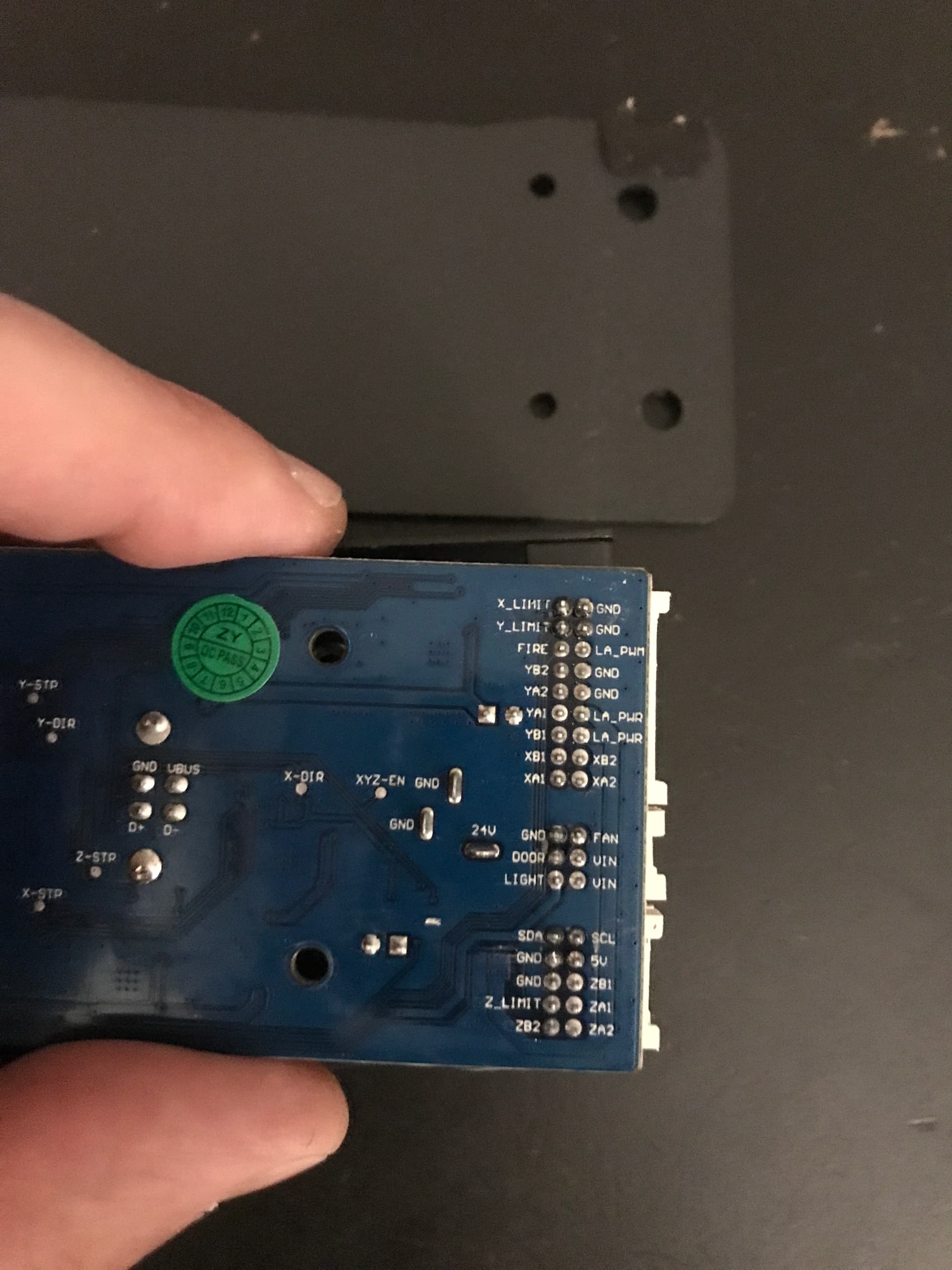
From the looks of it the OLM-MAX-V10 mainboard is fully capable to control the z-axis, at least hardware-wise. All it would take is the driver chip and a few auxiliary resistors and caps, provided that the firmware contains the necessary code to drive the z-axis.
Has anyone successfully managed to add a z-axis driver to the mainboard and is the firmware able to talk to the driver?
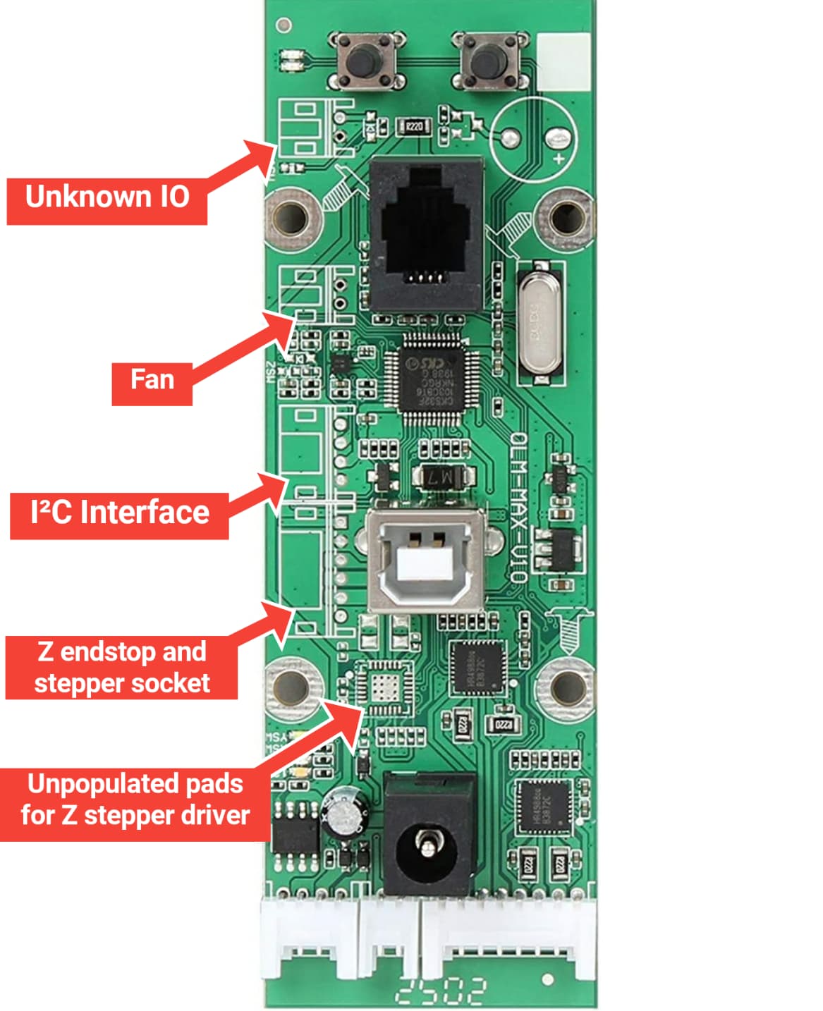
I annotated an image that shows all the unpopuled things on the board.
If it is as easy as soldering a A4988 driver to the board then I’d rather go that way than adding yet another stand-alone device to my collection.
Now it would be interesting to see if Ortur added the necessary code into their firmware. From a quick test last night it seems that at least something is happening when I try to control Z via laserGRBL. X and Y lock up to hold position, which is a good sign. Haven’t tried LightBurn yet but the results should be the similar.
I haven’t made up my mind yet what I would use it for, but I guess either a small stepper to adjust the laser or to lift/lower a platform under the laser.
I for one fully support you attempting to populate those spots on the board. I think there’s a chance that some level of Z-support was left out of the firmware as I know that LaserGRBL has special GRBL builds for Arduino that exist only to remove Z-axis support as it’s necessary to support a 2-axis laser but I could be wrong.
Worse case is you could compile a custom version of GRBL. Might be a good time to force Ortur’s hand in complying with their GPL commitments and releasing the source.
mmm not really. needs a custom firmware and is not only the stepper driver that is missing
more amps would be required and would also require a better power control
i am not an expert on the electronics part of it, but i am sure is more that just hot air a stepper driver in
Firmware does not control Z currently, but i you have the skills you could modify the source code. 1.4 is public, 1.42 not yet is being cleaned and commented as we speak.
I’d would also be interested in the source but I can’t find it anywhere.
I hooked the mainboard up to the oscilloscope and it seems that the firmware has the necessary code parts to control the missing stepper driver. I can see nice pulses on the STEP pin whenever I click one of the Z-up/down buttons and the DIR pin toggles nicely between HIGH and LOW depending on whether I click one of the Z-up-buttons or Z-down-buttons.
7 resistors and 6 caps.
I can see that a better power control might be necessary. I have ordered a stepper driver which should be here in a few days and then I’ll run some experiments.
That’s promising. I suspect Z-homing has been disabled in firmware but probably wouldn’t want this anyway depending on plan usage. Can you see if Z is activated during homing process?
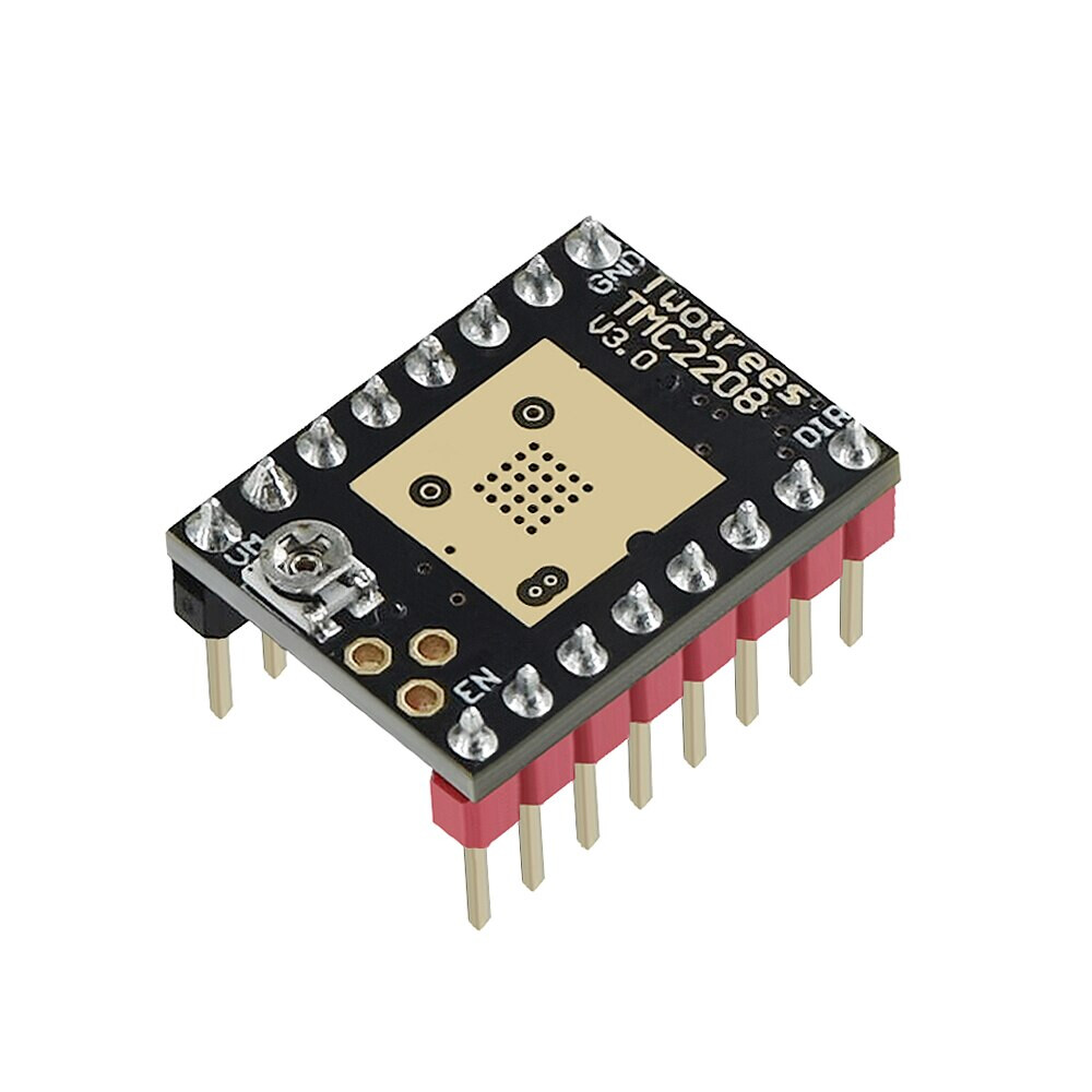
I haven’t received the HR4988 driver yet, so I wired up a TMC2209 board and I’m happy to say that it works.
That on the other hand means that even if the HR4988 (and all the other missing auxiliary components), when soldered to the main board, does not work, one could still grab the signal from the mainboard and feed it to an external driver and be able to control a stepper via the jog buttons.
Here is a video on Youtube where you can see me control a stepper via the unpopulated pads on the Laser Master 2 mainboard from LaserGRBL: Video on Youtube
Excellent progress. The clicking sound in the video, is that from a button press or that’s coming from the stepper? Overall, the driver seems to be driving the motor more quietly than the factory part.
Oh, that’s just me clicking the Z jog buttons . The TMC2209 runs in StealthChop mode so it’s significantly quieter than the HR4988. I should get the HR4988 in a few days and then I’ll compare the two.
I wanted to know the exact version of the motherboard present on my Ortur lm2 pro S2 and I had the pleasant surprise to see what the free entries on the card are for. Maybe that can help?
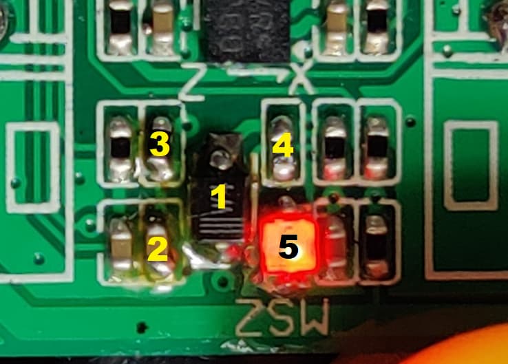
After a couple of days of tinkering everything seems to be working just fine. I populated all the empty spots and I can now control a third stepper directly from the software.
Area 1 is the most important one. I added an HR4988 stepper driver, 2 big sense resistors and a couple of smaller caps and resistors. Two resistors act as potential divider and set Vref. I chose 1.15V which, in combination with 270mOhm sense resistors, should result in a drive current of 0.5A.
Area 2 had a pull-up resistor for the Enable-pin of the HR4988 missing.
Area 3 now contains all the circuitry for the LED that’s lit up unless the Z-endstop-switch is depressed. I’m not planning to add a switch for the Z-Axis but it’s nice to have that light so I added all the missing components.
Area 4 is the added socket for the stepper.
Video on Youtube:
Now, If the laser is running at 100% and all 3 steppers are active, It would theoretically draw more current than the PSU can supply. Upgrading to a 4A PSU is an easy fix.
Realistically you wouldn’t be doing dynamic Z-axis motion for laser cutting anyway. Really only for focus, material height adjustments, and multi-pass z-heigh adjustment. So you’d probably be okay.
Are you thinking to allow for laser module height adjustment or bed level adjustment?
Right now you wouldn’t be able to home without a custom GRBL build. We need to followup with @OrturTech to see where and how Ortur GRBL source code can be accessed.
GRBL Itself is GPL 3 so Ortur are obliged to release their modifications. Gil mentioned earlier that the source was available but nobody seems to know where. We’ll just need to followup.
I imagine it wouldn’t necessarily be too difficult to come compile your own firmware but would be far quicker to start from a known working base.
0402 3300 Ohm resistor (current limiting resistor for the LED, other values possible depending on how bright you want the LED to be)
0603 LED
Even though it should technically enable the Z-limit switch, this function seems to be deactivated in the firmware. So pretty much all it does right now is turning on the LED when a z-limit button is not attached or an attached button is not depressed and vice versa.
__
The problem is that as soon as there is movement even on only one axis, all other steppers lock up to hold position. So there is definitely a current draw even though Z doesn’t do anything most of the time.
__
I bought an adjustable mount for the laser head and the plan right now is to 3D-print a bracket for the stepper and then see how that works out.
Hmm… You’d think it could support at least 1 additional stepper since that’s normal, especially without a laser drawing current. Curious if there’s something else potentially going on. Or maybe just your new stepper draws more current than the original ones.
 . The TMC2209 runs in StealthChop mode so it’s significantly quieter than the HR4988. I should get the HR4988 in a few days and then I’ll compare the two.