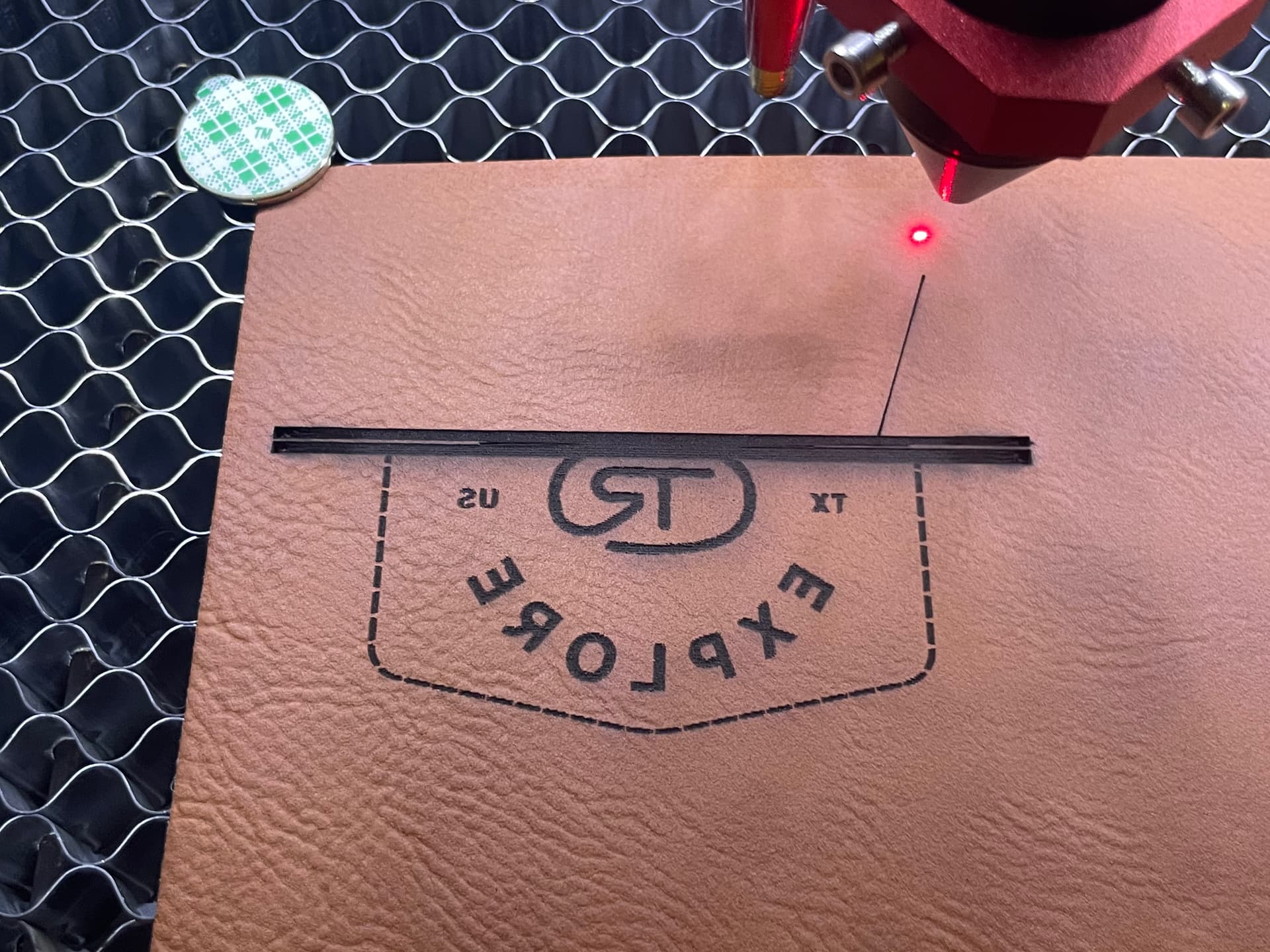
I recently got a Omtech 60w AF and it is acting funky. Tonight, I was testing it out and it was running decently, and about 60% in it starts running continuously creating the big black line you see in the picture. It’s done that every time I have tested it (3 times). Now when I run the file it runs continuously from the start, and even when I hit frame, the laser fires continuously as well. Any help is GREATLY appreciated. I researched and couldn’t find any information. Thanks!

The lps on these are controlled by two signals.
The pwm is feed to the IN of the lps and controls the pulse rate (percentage power) and the L input ‘enables’ the laser to fire at the pwm percentage.
The pwm is continuous from my Ruida for the running layer and only L ‘fires’ the laser.
I would check the voltage level at the L input. If the laser is supposed to move, but it’s moving and lasing… L should not be low unless it’s supposed to lase.
The black bar, without some explanation of what it’s supposed to do and what it’s doing is kind of moot. What is its supposed to be doing?
I know you know, but I’m not clear…
If I’m understanding you correctly, it’s lasing as soon as you press ‘start’?
![]()
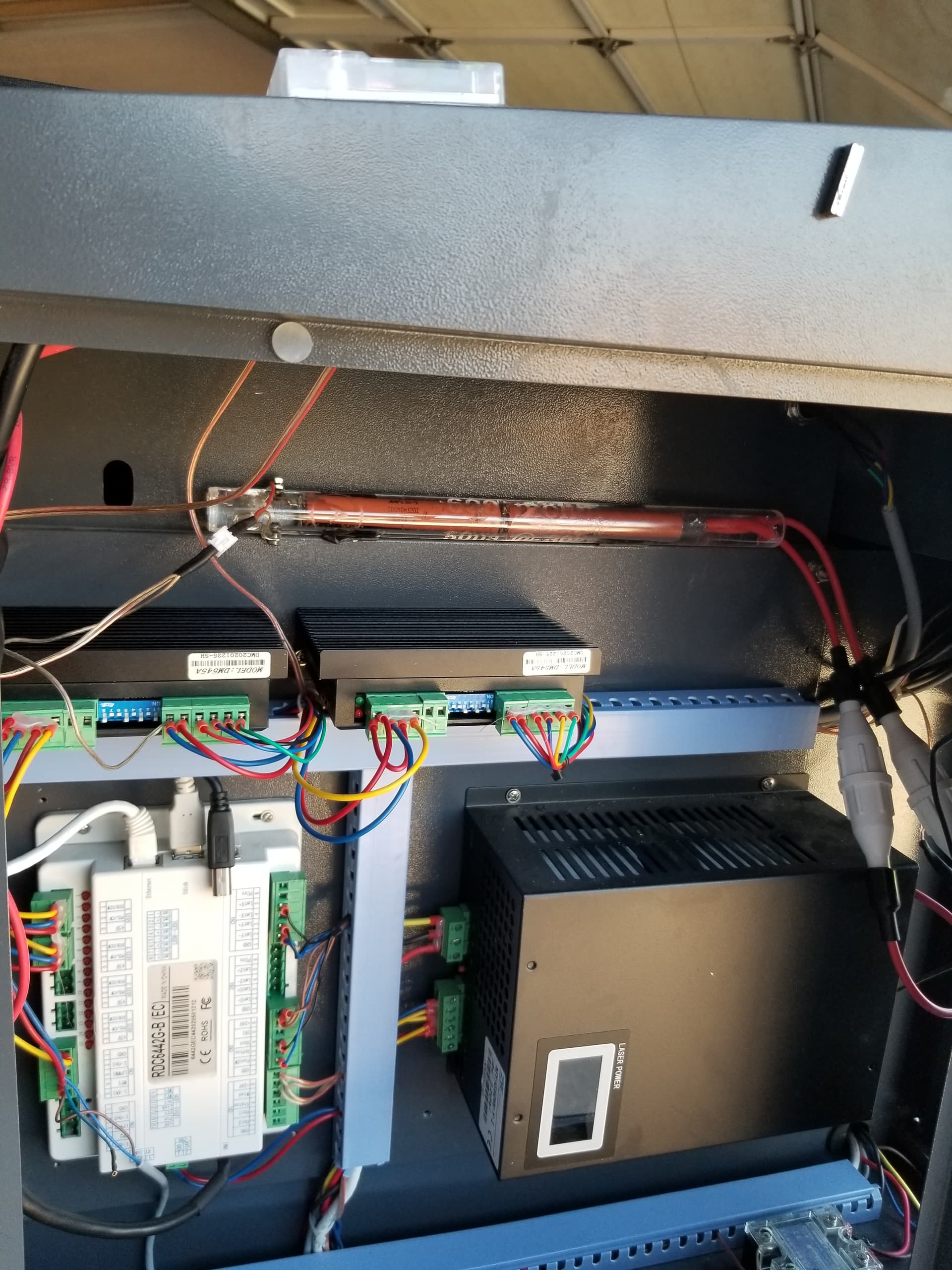
The JYE power supply on my OMTech 60 W (red/black) laser failed the same way a couple of weeks ago, with the first symptom being continuous firing while framing:
I described the symptoms in some detail and OMT sent an anonymous replacement power supply in a few days:
I think it’s also defective, but in a more subtle way:
So I bought a Cloudray power supply and will compare its output with the anonymous supply. If they’re the same, then crappy low-PWM regulation is just how these things work. If they’re different, then I must convince OMTech their supplier has a QC issue.
Anyhow, I think a failed supply is more likely than a failed controller.
If you measure the L input to the lps, it probably remained high (off), indicating the lps.
I’d like to know how he got those scope photos, along with where and what the trigger is. Mine are all over the place.
I haven’t read it in detail, out in the hot garage watching a job run,
![]()
They’re from an ancient (and cranky) Tek AM503/A6302 Hall effect current probe, which is absolutely PFM for non-contact DC to 50 MHz current sensing:
The oscilloscope is a DSO Shell, the worst scope you’d be willing to use:
But it’s way easier than hauling the real scope over to the laser for this sort of low-frequency glitchery.
The traces single-shot trigger on the leading edge of the current pulse, which works with manual shots on the Ruida’s control panel.
Even a crap scope beats a voltmeter which beats nothing at all… ![]()
That is really slick… My scope cost $399, these are running $1500 - $2000… that leaves me out in the cold…
Do you know what ‘signal’ was used as the trigger ?
Looks like something slick for a diy…
Ran across this a while back… supposed to be from Ruida

Thanks
![]()
To be fair, I got the Tek probes before they became eBay collectibles.
The trigger is the leading edge of the laser current signal, converted to a voltage by the Tek probe: the DSO-150 isn’t fancy enough to have an external trigger. [grin]
At some point I must poke at the L-On and PWM inputs, but I’m pretty sure they won’t show anything surprising. The old supply ignored its L-On input and the replacement pays attention to the same signal, so the controller continues to work just fine.
OMTech also sent me that “Statement” when I pointed out the KT332 was totally white-label anonymous. Apparently I should be relieved it’s been anointed a Genuine RuiDa, even if it looks like an outsourced thing retconned into the family.
My Ruida/lps requires both of these to work
L-On1 → L of the lps
LPWM1 → IN of the lps
That would have broken my machine. The Ruida on mine runs the pwm as soon as you press ‘start’ on the console. L-On1 goes low firing the lps at the already running pwm rate. Escapes me how it could have worked missing a required control signal… ![]()
- Blue trace is the voltage across the mA meter.
- Purple is the L-On1 and the falling edge trigger for the scope.
- Yellow is the pwm… it’s period is 1mS. Normally it’s period is 50uS. It’s running an engraving…
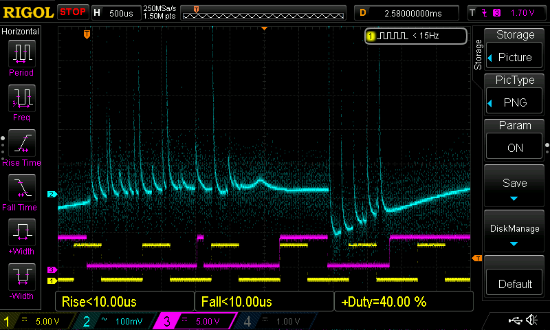
This is a straight line at 50% pwm…
Faster sweep
As you can see it doesn’t turn ‘on’ until L-On1 (L) goes low.
This has been the best I’ve been able to get so far.
I just want to know the lps response time…
![]()
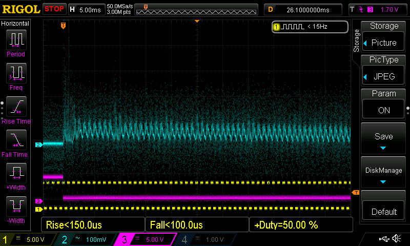
Having the HV supply fire continuously at whatever the PWM input specified, even with the L-On signal inactive, was the clue telling me the supply was kaput. I’d be tempted to poke around at the input circuitry to see what failed, except for my morbid fear o’ dying.
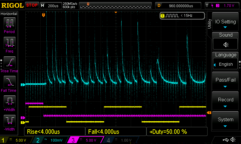
Looks like your supply produces the same high-amplitude spikes after the enable goes active, even at 50% PWM, as OMtech’s anonymous replacement. Yours seems to settle down faster than mine, but the claimed “1 ms” response time seems mmmm aspirational.
I’ve been a radio amateur since the mid 70’s, worked on electronics when I was a kid.
I’ve gotten across 480v once, that was shocking… and bit by 15kV supplies.
I know of no person that has been killed by one of these. Almost 80% of all electrocutions in the US is from the home mains.
It wouldn’t hurt to poke around with an ohm meter and see what you can see… might surprise yourself and fix it…
Let it sit for a few hours…
The input circuitry is not complex, there are schematics floating around out there. If I remember right the L, H and P inputs basically control the on/off of the pwm generator driven by the IN input. This effectively shuts off the pulses that control the ‘power’…
I have a big resistor to the hv so I can read it on the console…

600 meg ohms
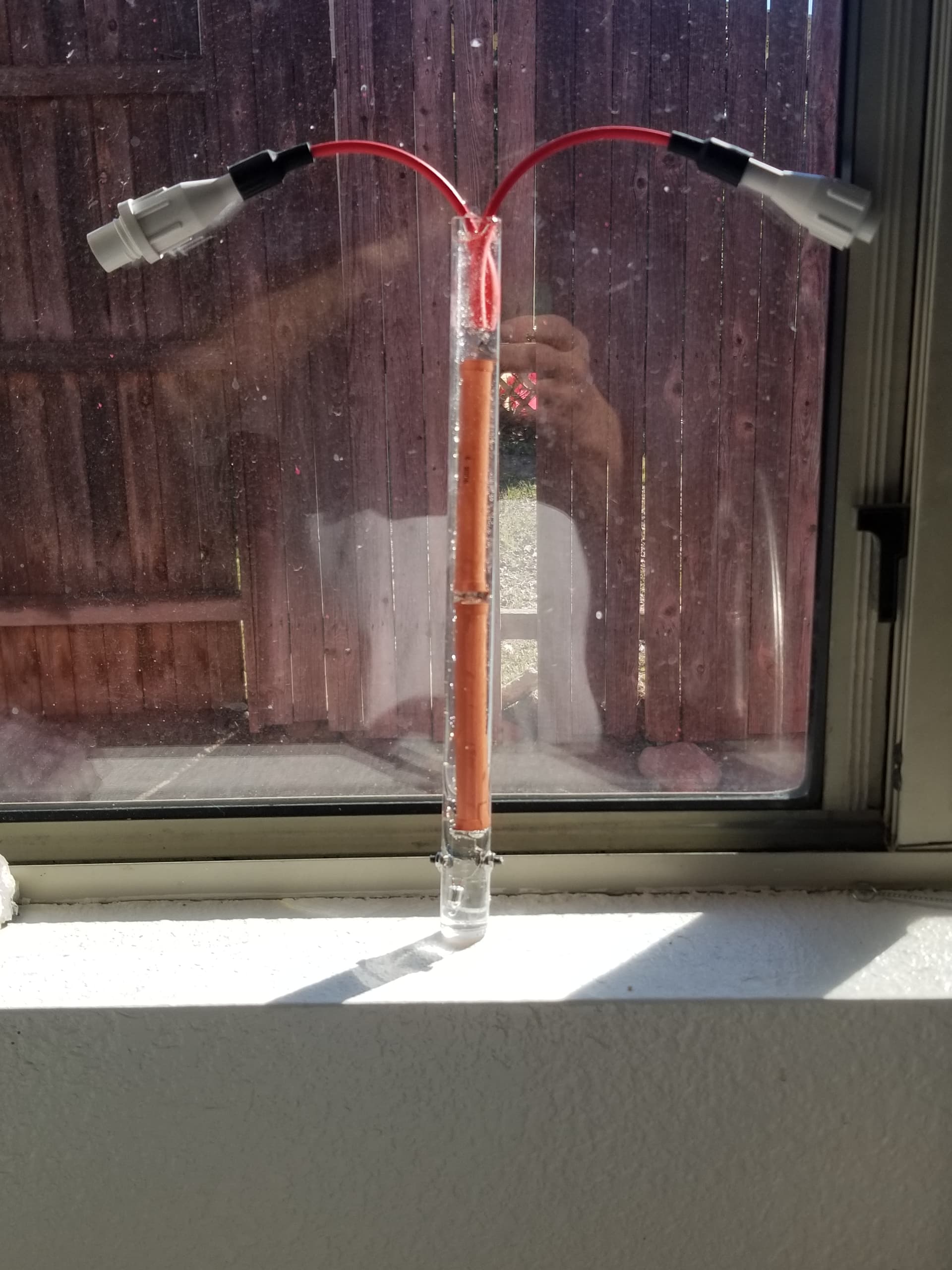
In the machine…
It does drain off any ‘residual’ high voltage…
![]()
It’s happened before!
There was nothing obviously wrong with any of the components / traces associated with the inputs, but I admit to not pulling the PCB and looking for mysteries.
The risk/reward ratio is entirely too high to justify building a test setup and I’d rather not use the laser tube as a fuse, so I’ll stick with a black-box replacement, crappy though it may be.
Hey! You want a lightly used, known-bad CO₂ laser power supply? USPS says for 16 bucks it can be yours! [grin]
Check out Don’s stuff, he hangs out in Makers forum, I think…
![]()
You guys are so helpful, thank you!! I’m looking at the Cloudray power supply as I need it quickly and don’t have time to keep going back and forth with Omtech. Did you get the 110V or 220V? And how had it worked out for you?
Thanks!
I installed the Cloudray (it’s the 110 VAC version to match everything else), verified that it worked, got the no-name replacement from OMTech, swapped it in, and that one has been working ever since. The Cloudray sits on the shelf for The Next Time.
AFAICT, they’re identical internally except for the meter / display on the OMTech boxes. I got the remote meter with the Cloudray, plugged it into the OMTech, and it worked fine.
Which is defining “fine” as showing the same crappy regulation for currents under about 25% PWM. Given the hardware seems identical, I assume they behave the same way, so there’s no reason for brand loyalty.
This topic was automatically closed 30 days after the last reply. New replies are no longer allowed.