Omtech K40+ and Omtech 50w power differences?

I’m not sure if this is a software setting or not and I have limited experience so any help is appreciated.

I have a 1 month old K40+ that I absolutely love. I run it on light burn, did my material tests and made some outstanding pieces. The only downside is the workspace, so I scored a deal on an older 50w Omtech and tried using my material settings with it and they are nowhere near close.

For instance, on 1/8" Birch ply, 275mm@14% I get a great photo engraving, nice depth, color, etc. I tried the same settings on the 50w and it gave a very lackluster finish, like a very light pencil etching. So I bumped up the power to 20% and it burned the edges, while still giving a faint image. It also will have random “shadows” and high power lines.

I also cannot get it to fire properly under 11.5% while the K40 will do 3-4% no problem.

Any insight?


Since the K40+ doesn’t use a minimum/maximum power setting I’ve been wa dering around wasting materials. I have included the run time on the machine in case the tube or power supply was weak but seems to have low actual working hours.

I primarily want to use it for acrylic engraving on 1/8 but these power settings are much too strong for what I was doing with the K40

In addition to having a diode laser, I have had a “normal” K40 with Mini GRBL and a OMT 60 watt laser.
I was very fond of my K40 as you are and also only had the bed as criticism point.
But, the problems that you describe I do not mean I have had. Once the mirrors and lens are perfectly adjusted and the focus is on spot, I can make very fine and delicate engravings with my 60 watt laser, which is probably more a 50 watt or something in this direction. It demands quite a bit of time and many experiments to find the correct settings and reminds me of the transition from diode laser to CO2 laser.
The lower limit of our laser is at approx. 10%. Depending on the job, I use minimum power to avoid overfire corners or ends of lines. To find the respective settings, I engrave a 20x20 mm square (Line Mode) with the desired speed and a suitable power setting. Now I reduce minimum power until the corners are neat and without difference in the thickness of the rest of the square.
Your material test looks like wrong settings are used, too much power and / or you are not in focus.
If you draw a square 20x20mm and set it to Fill and run it with 300mm/s and 30%max. /12%min. Power, as a starting point, what does it look like?
PS. I believe that OMT machines in this league are limited to 400mm/s from the factory, my machine was born with these setting.

The focus is on point and the mirrors are aligned. I performed a ramp test before this. I have no issues with detail, I did a very large piece with outstanding detail but the minimum power values between the 40w and 50w laser doesn’t correlate to me. I’m also not sure if this is a settings issue. 275@14% on the K40 gives me great blacks and engraving details, whereas the same settings on the 50w were like a washed out water color. I would post a picture but it’s of the wife and I and she said not to, so I’ll have to run another piece first.

As far as the speed values, the x axis was 500mms and the y axis was 300mms, in the files I got from omtech. The machine was originally advertised as 600mms. I changed only the y axis value to bring up the speed.

Even at the very minimum 11% power to fire, I get random line intervals that are dark or much higher in power, but only for a moment, not the entire pass. I’m also not sure if i should set a fixed value like the K40 or give it a range of say 20-40 for example.

I ran a 10% to 100% test and it was WAY too much, half the test piece was cratered through.

Tomorrow I’ll run a test like you suggested, thanks.

Sounds strange, are you sure your tube is okay?

100% - I hope that with a “regulated” HV power supply, otherwise you will not have this tube for quite a long time.
What does your ampemeter show?

I couldn’t use my old settings from my K40 on my OMT 60 watt machine. These are two completely different machines. (I don’t know if your K40+ is different as my standard K40)

There may not be an easy comparison between the two machines.


A dsp interfaces to the lps differently than most grbl boards. The lps has two control lines, laser enable and pwm. Most grbl type boards do not have this control ability and operate differently.

If you have a pot to control power, you have a manual power control, you can’t control the tube current with your pwm.

The dsp types, control tube current with the pwm and enable the tube when it needs to lase.

A dsp running a line at 50% power will lase for the entire line with 50% current through the tube.

A grbl type running a line at 50% power will lase at 100% power for 50% of the time.

This changes the impact of the beam on the material, since the dsp is striking with 50% while the grbl is using 100% power.

The call this power control, but it’s much like a dpssl laser in that when it lases it lases at 100% power.


If you look at a good quality tube, such as many RECI I’ve looked, it will tell you a 60W tube has a power range of 12W to 60W, meaning the tube isn’t recommended to operate properly under 20% power.

If you measure the length of the tube, it will relate to maximum power… my 50W OMTech China Blue measured about 44W and that was pushing it. They knew when they built it and labeled it, knowing you can’t have 50W in less than a meter length of tube…

Tube will draw current before it will lase, this doesn’t mean it is lasing, just being excited.

If you run this low current range, it’s claimed to be as damaging to the gases are running too much current…


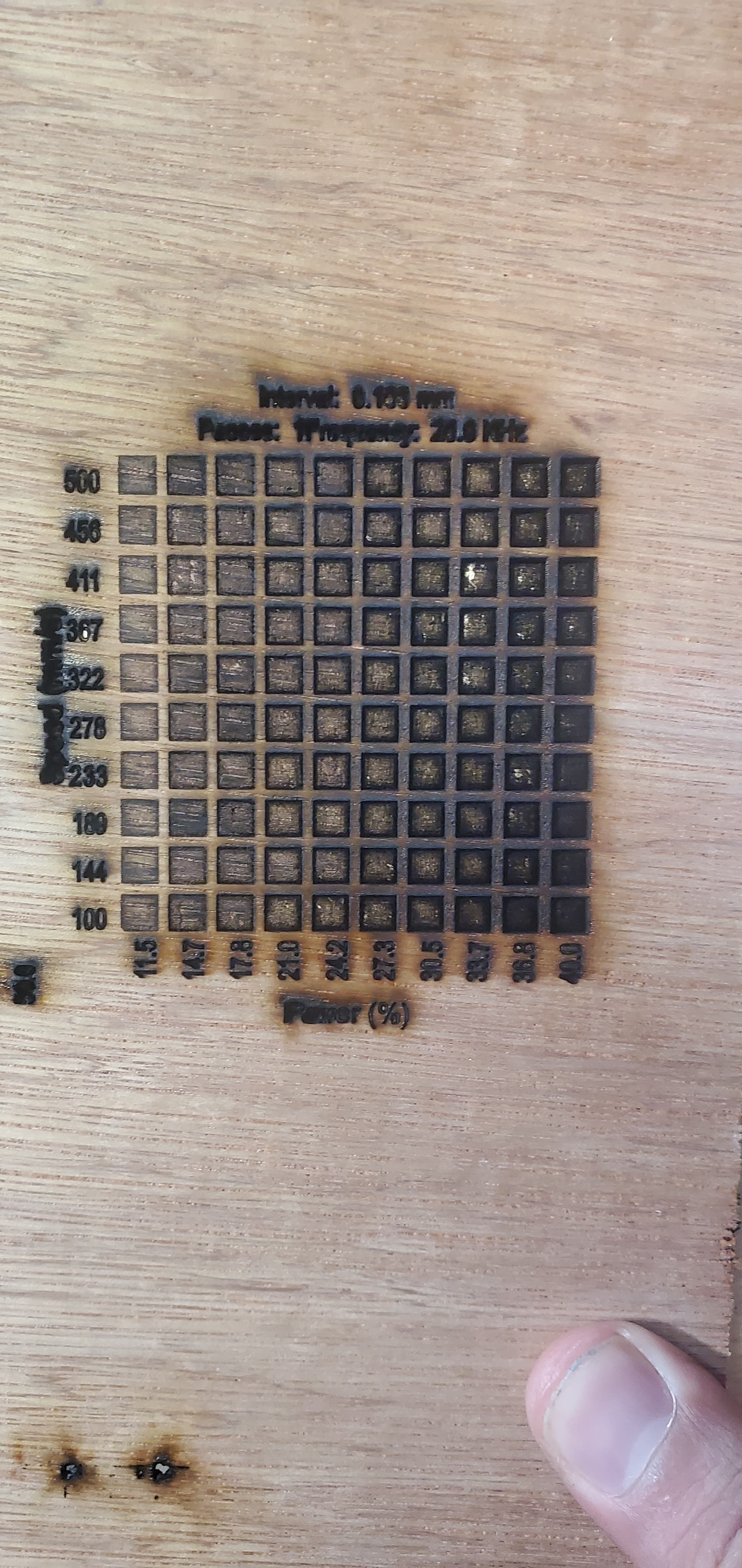
You should setup your lps to ensure you get the full range.

Make sense?

This is relatively moot… The fastest you can run and still toggle the lps is dependent on the lps response time.

LPS have a pretty standard response of <=1mS. meaning the response time of the lps can’t be toggled faster than 1/1000 of a second. At 1000mm/s the best dpi you can have is one dot/mm or an interval of one or 25.4 dpi.

At 500mm/s, the head is half speed allowing twice the time for the machine to respond making 0.50 interval or 50.8 dpi is possible. At 250mm/s the available time is twice that of 500mm/s. An available maximum interval of 0.25mm or 101.6 dpi.

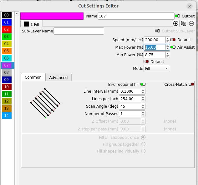
An interval of 0.10 (254 dpi) requires 254 dot/inch or 10 dots/mm. Fastest speed is 10 dots/mm or an interval of 0.10… 1/0.10 = 100mm/s
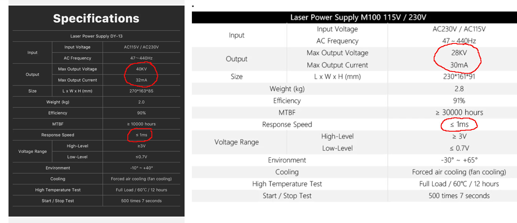
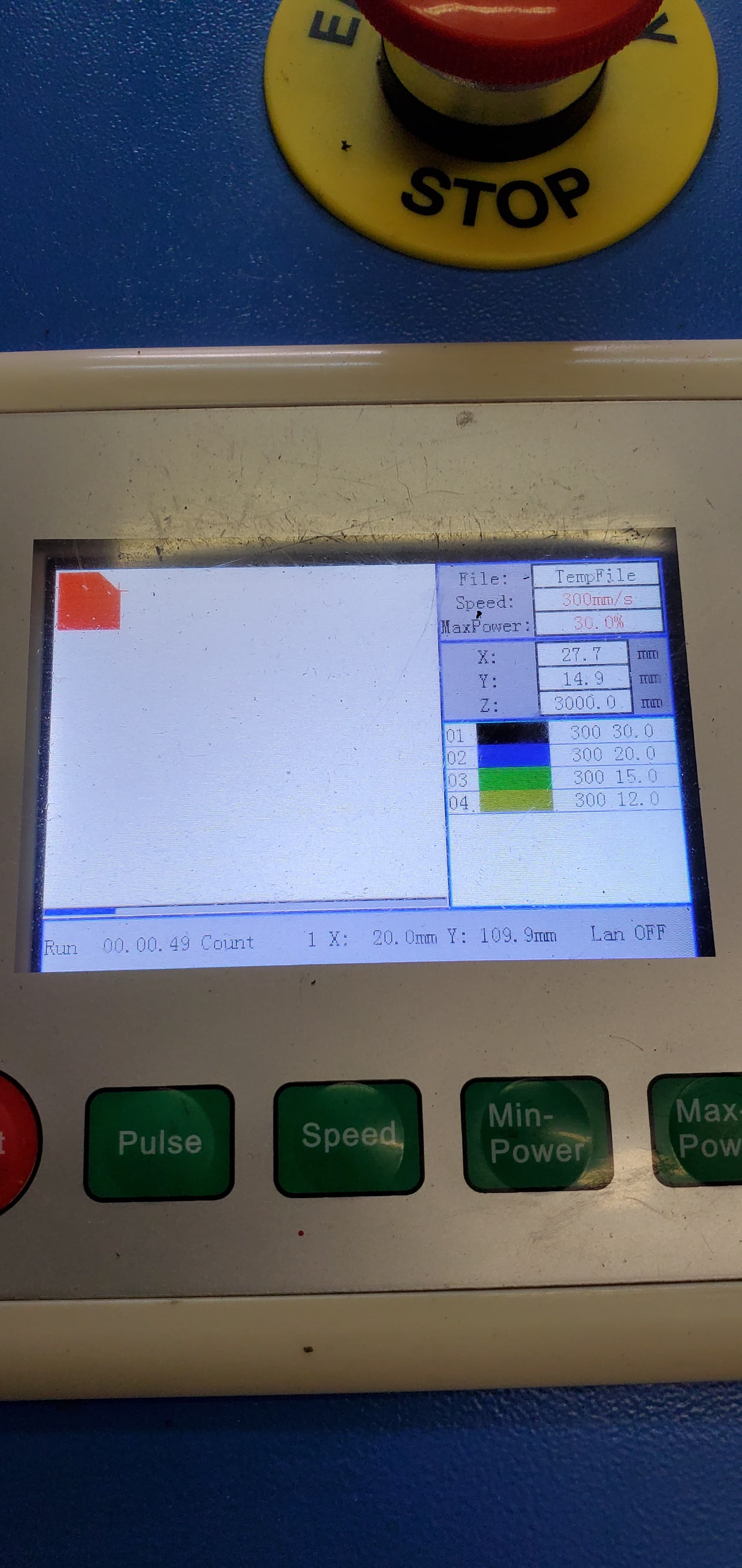
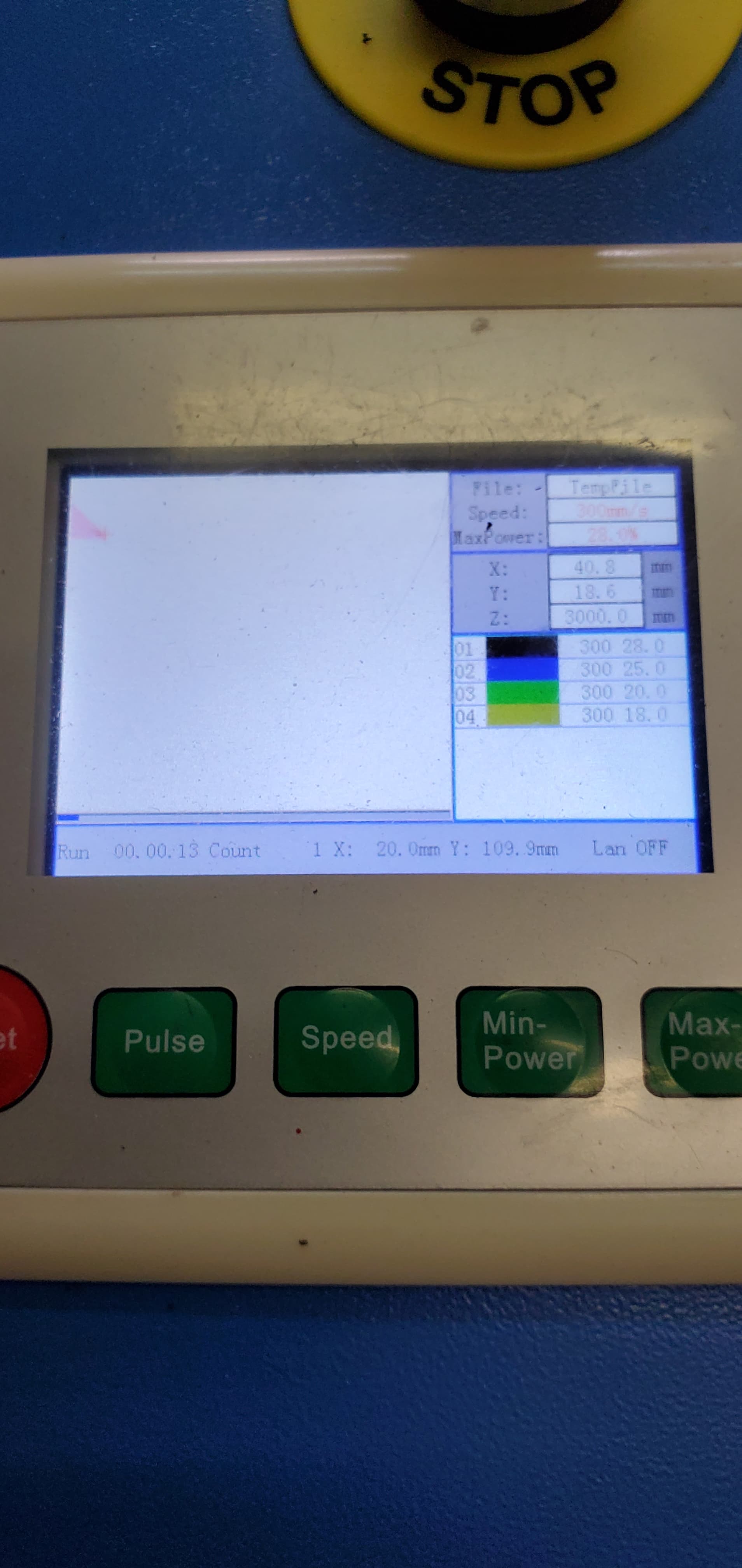
Here are two lps

The supply that reaches 40kV will respond faster than the one that only reaches 28kV. Notice the MTBF values of each.

Good luck

:smile_cat:

I’m assuming it’s okay, it has a total on time of 157 hours, which should be quite low, but it was also made in 2018. I ran the same photo three times and the random dark spots were in the same places each time, which has me leaning towards a settings issue.

No amp meter but it looks like I’ll need to install one.

Most of it makes sense, I’ll definitely have to read it a few more times.

So if head speed determines DPI, and running slower increases the resolution, what happens if I choose a 300-500dpi photo?

How should I be setting the power ranges for a photo? Fixed at 20% if the test piece comes out well or giving it a full range?

What are options or workarounds for limiting power? The acrylic work I’m doing likes a VERY light engraving, since I’m using LED with them. I can keep doing a good portion of it with the K40 but I would like to do some large scale stuff too.

This isn’t exactly what I’m saying.


Have you ever plugged a serial device into something and gotten a line of gibberish. That is one device not expecting the same speed bit pattern…

In simple terms you are operating at a much higher rate or exceeding it’s bandwidth. Driving it faster than it can perform the requested action.

IBM has a good term for this results may be unpredictable

It is a bandwidth issue, running 300 baud on something that maxes out at 110 baud…

I don’t know what happens, but I see a lot of people running 500mm/s attempting 300 dpi and they do get results… what’s happening? … don’t know exactly … wish I did… and it’s probably a bit different for each machine.

My machine will actually run > 1500mm/s, but it’s really for academia … it’s not really usable for any real work…

Not to mention the overscan means it’s spending more time slowing down, turning around and speeding back up than it is actually working on the job…

It does have a pay off, being able to greatly increase the acceleration values, so it turns around faster. My X acceleration value is ~45,000mm/s^2.


I’m just saying that you should know the limitations. If you are not getting the desired results, maybe it’s related to this?

This is one of the issues with a big machine… You usually can’t get to the lower power range you can with a lower power tube.

If in doubt slow it down. Think about how the beam is damaging the material. That’s your best option when things aren’t working.

Sing out if you have questions…

:smile_cat:

I did this and some extras. I accidentally had the second square set on 2 passes, stopped and started over.


Ran some more, I’m even more confused now.

Can you send the LightBurn file from the last attempt? (only from the 50 watt machine)
I assume that the upper part is from your 50 watts omt and the lower one from your K40, is it really understood?

They are both from the 50W. The only difference was the stroke setting, 0* vs 45*

ok, that’s understood.
Send the material test file from your first post, I just want to see if there is anything with your settings and then I will run your file tomorrow with my 60 Watt and see what it brings.

Unfortunately I fat fingered it and didn’t save it. I can build it again though.

What would cause a 45* angle to burn so much hotter?

Square test.lbrn2 (7.1 KB)

It’s nice that there is the time difference between Europe and the USA, so I get to see LightBurn’s experience conference live in the evening/night and I can work normally during the day :wink:

I have run your file, without changing anything, knowing that the power should be reduced by about 20%.
The result provides the answer to at least 3 of the important questions.

The two fields that have just fallen out of my 4.3mm test birch plywood are the 45 degree engravings.

It is reasonably logical that this happens. At 45 degree movements, both axes work simultaneously and the minimum power setting and ramping up/down do not work or not work optimally. You can clearly see that during the start-acceleration and stop-deceleration power is not reduced. Especially when there is already too much power, the result becomes extremely clear.

I often and happily use crosshatch, but with very carefully balanced power settings and relatively large line spacing. To camouflage the edges, I like to use an outer edge round at the end, i.e. I run the project in line mode. (I didn’t use it in this test)

Another notable thing is that you are not using minimum power settings. The difference can clearly be seen by the square in line mode.
The one on the left is without and the one on the right is with minimum power setting.

The speed also plays a very important role, (primer when using the fill function). Often you don’t get the set speed because the distances are too short. Acceleration and deceleration cannot be achieved and the laser head takes a much longer path and time for the “wrong” settings and the power settings cannot be converted optimally.

Another important thing is the orientation of the fibers in the wood. The test also shows here that there is a clear difference in how the wood breaks and you have to be aware of this “problem”.


(bottom, same settings, only rotated 90 degrees)

Same test with modified settings.
On fields 9 and 10 (the squares in line mode) the focus has been changed to +6mm to clarify the difference with and without minimum power. What cannot be seen in the photo is that there are actually holes in the 4 corners of the items without minimum power.
nos. 11 and 12 are with correct focus, with and without minimum power.

PS. I like to use defocusing to get a darker effect when engraving.

I think part of this is related to the scan angle. Seen this before and I avoid any scan angles not multiples of 90. Lightburn warns you of this.

:smile_cat:

This is exactly what I describe in the upper part of my post.

Wow, thank you. Thatbis quite comprehensive. You are correct that I don’t use minimum power settings, the K40 doesn’t use them so I really have no good idea where to start with it but I’ll definitely start to use it.

The scan angle is still odd to me, I run all projects at 45* in the K40 and it makes a beautiful line pattern, especially on acrylic. Lightly frosted with sharp lines, the 50W not so much. I figured out shortly after sending the file it doesn’t like the 45* angle even at light settings, results in some very jagged edges, if I’m being honest, they’re all pretty bad, probably acceptable but not as clean as the K40.

The scan angle with acrylic should not matter… The material is very consistent and takes heat evenly.

Why would you want the Y axes to move when it isn’t necessary?


Most of us scan using the axes with the less mass. This is generally quicker and doesn’t induce unwanted mechanical harmonics into the laser.

If your interval is correct, I’d think there would really be no need for a cross hatch. I only use it with the fiber on metal, excluding the rotary.

You have no power control, except the pot.

There is no software control of the actual tube current. You can only change average power over time.

:smile_cat: