Laser: OMTech SH-G570 Blue and Grey
Ruida: KT332N(EC)
Problem: Geometry being cut gets more and more off as the job progresses
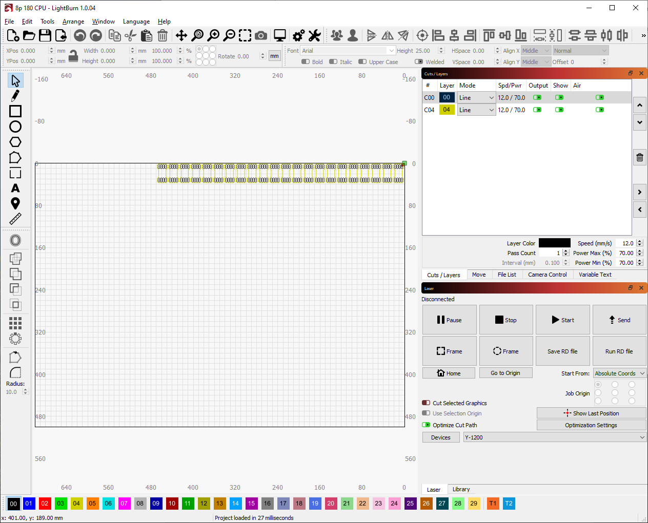
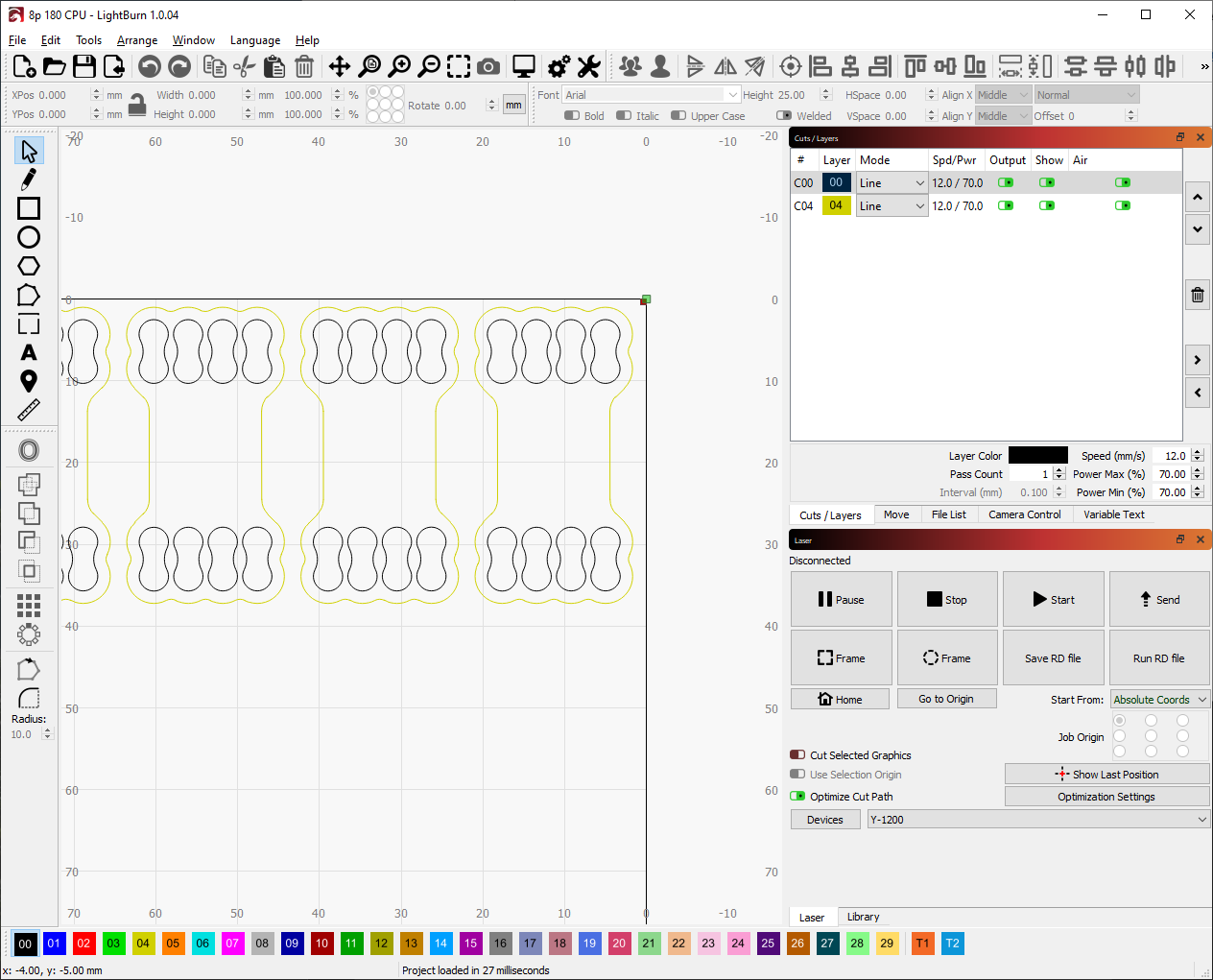
So this is a brand new device and I love it, however, the job keeps getting off focus which I initially thought was a backlash issue. Here is an example of what I see vs what I get:
Tightened the belts on all axis using the built in tensioners
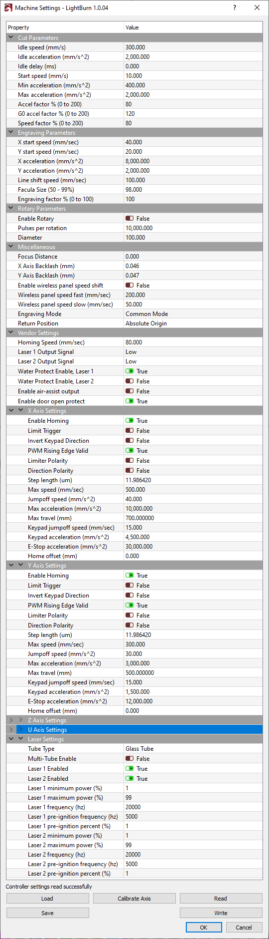
Used dial indicator to jog the axis in 1mm increments 5x one direction, 5x to return to its origin and found a backlash of 0.047mm - configured that in the machine settings and hit write
Slowed cutting from 12mm/s to 10mm/s
I also lowered the amount of pieces to 5 total cutouts and out of those 5 I am getting 3 acceptable pieces, 2 that are just too off for my comfort. I posted this to Reddit asking if anyone has had better ways of calculating the backlash here and have had several responses talking about acceleration and speed being the main culprits or possibly the stepper motor drivers.
My desire: has anyone else dealt with this issue and if so can you walk me through getting this fixed? Here are my machine settings if this helps
I think part of what you’re dealing with is the “kerf” of the laser beam. Just like a saw, the laser leaves a cut area of a certain thickness. You design seems to be so small and the cut outs are so close to the outer edge, that it is too close for the kerf. You might do a better job with a different lens that has a narrower kerf.
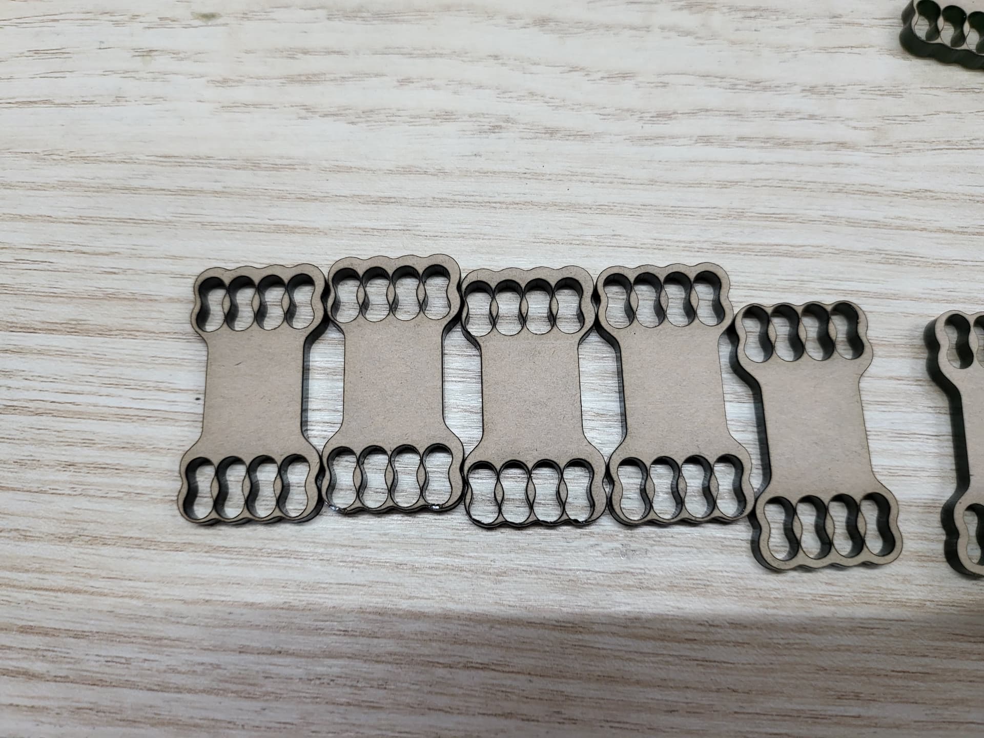
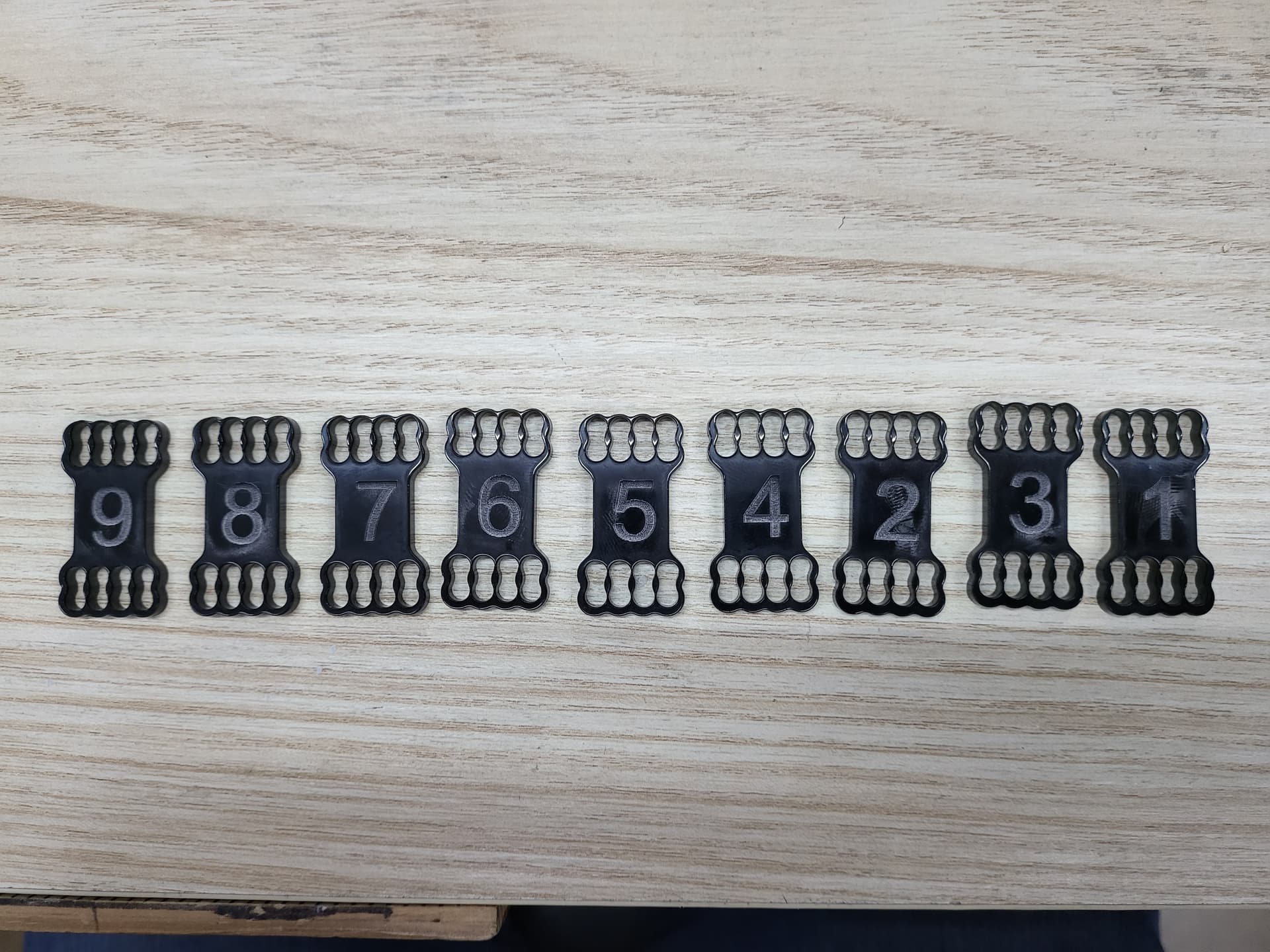
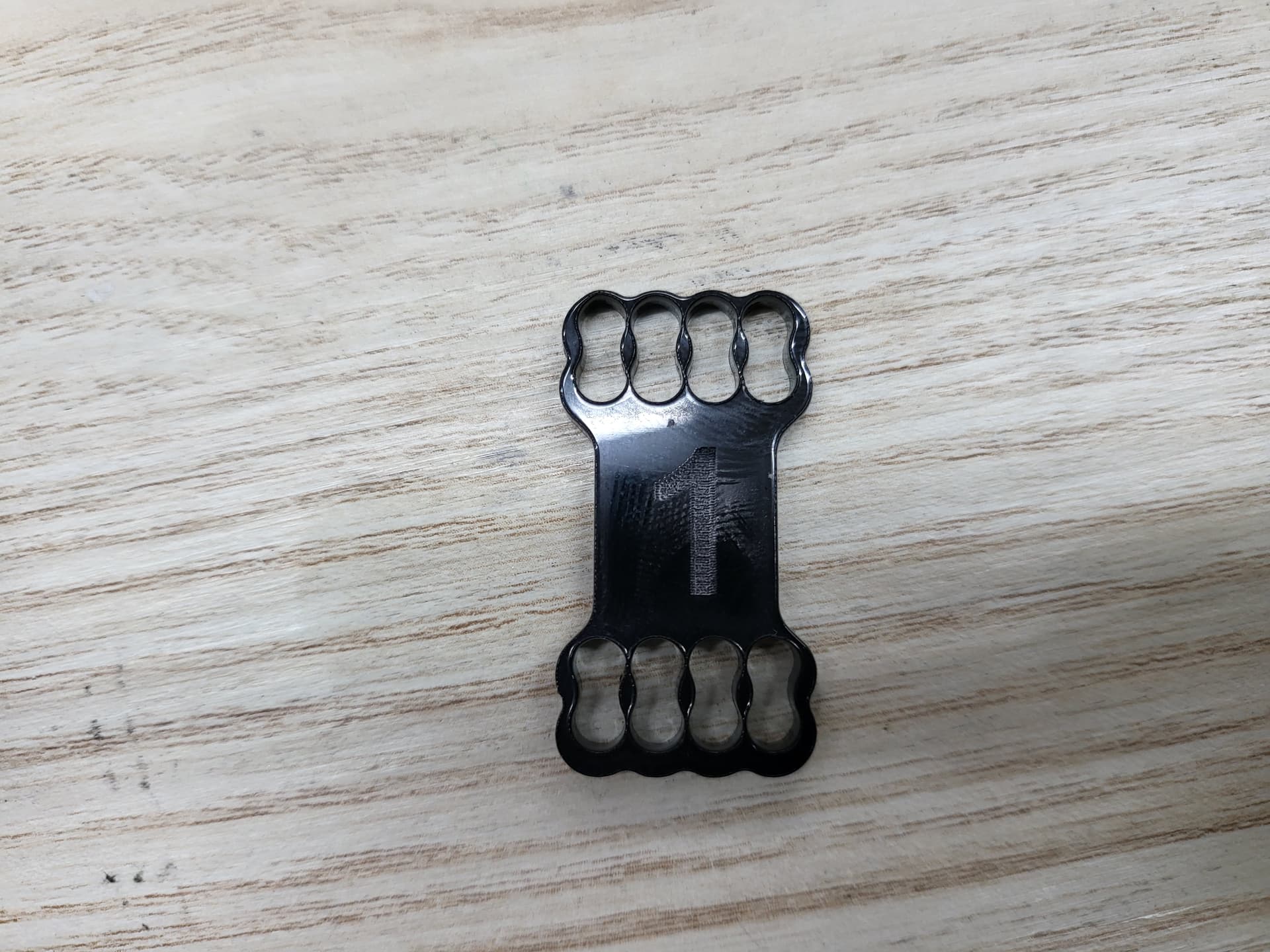
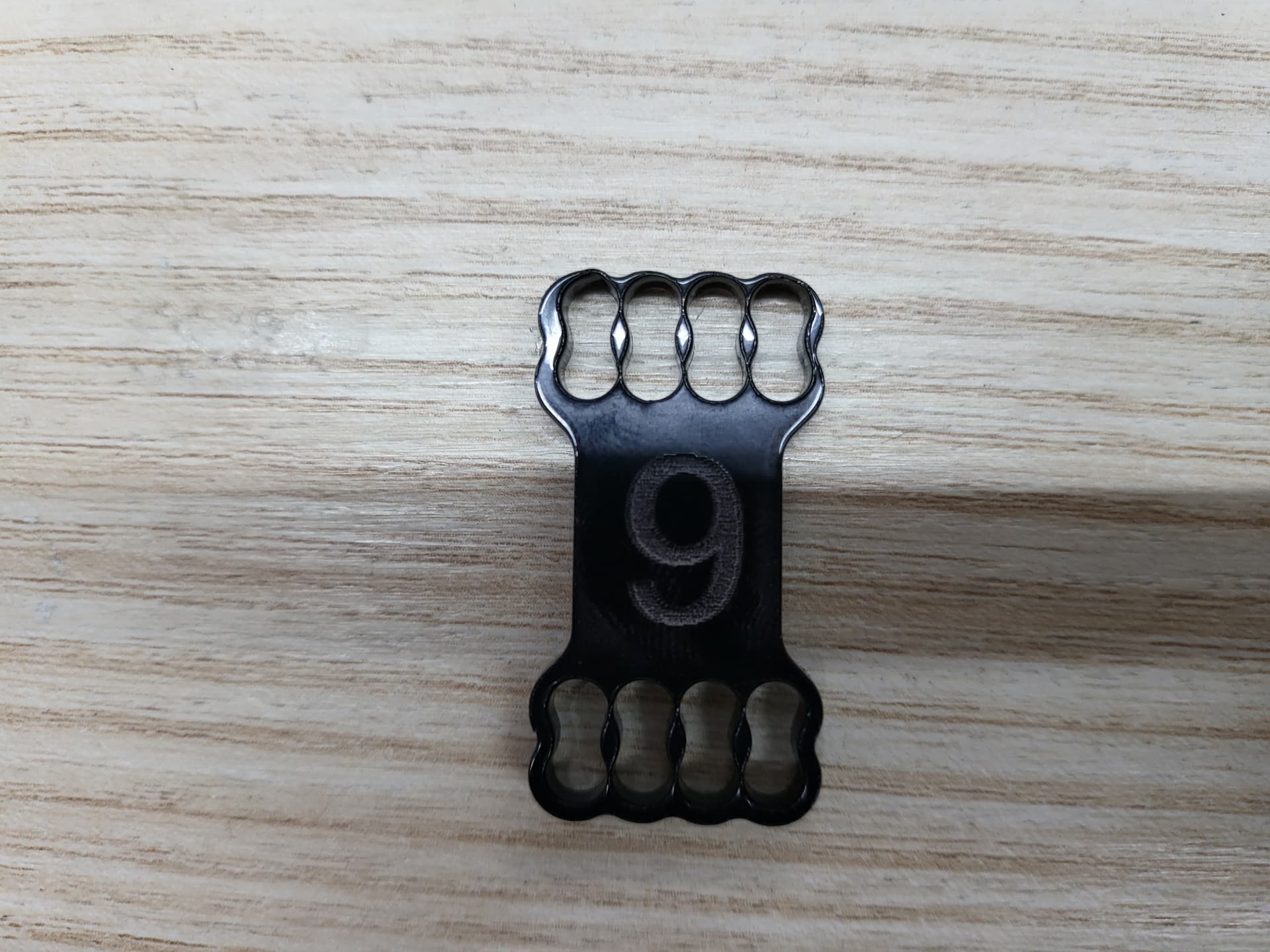
I understand the kerf and these parts are supposed to be small that is not the issue. The issue is the parts get progressively worse as the job continues. Here is a better example:
You can see the lines on the X axis are significantly further off on #9 than they are are #1. The Y axis is just off a bunch after doing the inner squiggly cutouts. Make sense?
Glad you know about kerf. Now it seems to me to be a calibration issue. The longer away from zero you go, the more the error of some sort adds up. I hope someone else has a clue, because I am now clueless as to what needs to be done.
Ensure you make a backup of your original controller settings, no matter what. If you lose a controller you lose all of that. I have two for the Ruida and grbl backup. Also means photo or something documenting the original settings of switches you might change.
Check the motor driver boards. They should be set the same.
Might even pick up some documentation on them and ensure they’re set properly.
I can’t connect, so I can’t look at my controller settings.
I’m thinking falling edge instead of rising, or vise versa when the stepper are supposed to clock…
Not sure if this will help, but i thought as a new user (my first post too) also looking for insight into an issue similar to yours (my raster engraves dont line up to my vector cuts) i came across this thread i n which someone states changing tthe ‘PWM Rising edge’ value in machine setting can help.
So I found a workaround for the issue but not a fix per se:
Instead of cutting the insides of all the geometry out first and then going back and cutting the outsides out all at once, I changed the way the machine cuts the parts out. I have the machine basically do each part to its completion before moving on to the next. That way the machine doesn’t have to return to another the piece it started on and be off track. Does that make sense? It doesn’t fix the issue of being off after all those movements but it does allow for me to cut the parts out with accuracy and no errors.
So the lines themselves are measuring accurately, its the spacing that gets off after so many moves. I haven’t checked the stepper drivers switches themselves because I don’t know what the switches when changed affect enough to go to that step.
It seems to be affecting both axis the same in this regard. However, when I cut each part, inside first, outside second and then move on to the next part vs cutting insides of all parts first, then outsides of all parts afterwards it allows for me to get each part out accuratly. Does that make sense?
If both axes are off then I’d suspect configuration of the step length/rising - falling edge type of configuration issues…
My mention of the hardware drivers are, that without any knowledge you can see if the switches are set the same for both parts.
It’s difficult to think of this as software, controller configuration maybe… Hardware wise this stuff operates pretty simply, so most of these issues come back to configuration. However I have a Chinese machine also… hard to figure it out sometimes.
I did try the vendor and they were referring me back to this forum. In communication they were talking about using RDWorks so I downloaded it and tried to mimic the job in the same way and the issue was still there so it wasn’t the software per say so what you are saying makes a lot of sense.
That being said I sent this information to the support email thread I have going on with them and I am still waiting for the response. I don’t know if this information helps but it only has 1 motor for the x and 1 for the y. The y motor is tethered to a long rod which allows it to move both belts simultaneously.
Referring to two motors I was saying compare the X and Y parameters and settings to see if they are the same. That assumption was that the X and Y motors are the same types. This, again, is making an assumption that only one axis is an issue. If both are problematic, they may just have the wrong values.
Sounds like you have gotten a ‘factory fresh’ configuration for your machine from the vendor to try and rectify the issue…
Can you tell if it’s accumulative, if you have a bunch of rows does the error grow?
@jkwilborn that is the solution!! I found the solution and it was a rising edge/falling edge issue!
ALL- the answer on my issue was found in the document “Configuring a Ruida” on the Lightburn github page. It is the very last section in the document and it walks you step by step through the process and it’s quick and painless! Thanks to a fellow Facebooker for the actual link, which I pasted below for anyone that needs help.
I just got word from the supplier’s support channel saying to turn the PWM off which is exactly what you were saying. We may have a solution! Thanks so much for the link