Optical Switches Ruida 6445

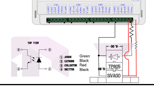
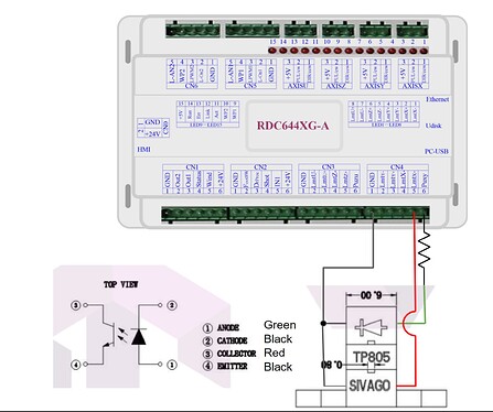
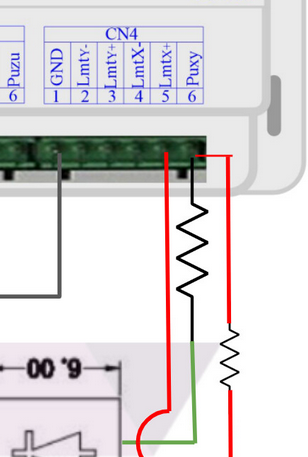
I am in the process of putting together my wiring for a conversion of a FSL muse over to a ruida 6445 to get away from the horrendous Retina Engrave software. The machine currently uses TP805 optical switches as its homing/limit switches. I am trying to decipher how to wire these properly for use on the Ruida. They act as NC switches with current passing only when it receives an IR signal. I have spoken with some that have said I must setup a pull-up circuit like in the first picture. This does not seem to match the user manual that shows you could hook up a simple NO switch between the LMT pin and ground. If I follow the user manual, the 2nd picture is how it would be wired.

The IR LED runs at a nominal 1.2v so assuming 5v input I would need a 190 ohm resistor to power the diode.


Any help would be appreciated.

The potential on the Lmt* inputs are at 24V… they appear to have internal pull up resistors on them… at least on mine… they operate without any external pull up or load. Hang your voltmeter off one and read it… meaning I don’t think you need the pull up resistor on the right of your diagram.

I’d run with the 2nd wiring diagram. There appears to be no information on how much current you can pull from the Puxy pin.

image

Although these are marked Lmt inputs, the Ruida has both home switches (-) and limit (+) switches… Once homing is completed, these switches are never interrogated again until a reset or reboot occurs.

Use the minus inputs, I.E. LmntX- and LmtY- for your home switches. You are using NC, so you need to tell the controller, these go high when active.

You need 40mA to run the leds…not sure what the Puxy can supply. I don’t think it’s meant for driving electronics… but I don’t know.

I’d think about re-computing for 24V supply on the led and use that supply…

That’s my two cents, and I’m tired… if something doesn’t add up to you please ask…

I’ll be out most of the day tomorrow …

Good luck

:smile_cat:

Jack, thanks for the response. From what I can glean from the user manual, all the output ports run a max of 500mA. If true that means I should be able to pull off the 5v output. I am away from my machine for the next week so I can’t get a multimeter hooked up, just trying to get everything straight before getting home to make the conversion run smoothly/quickly.

I could recalculate to run off 24v if absolutely needed, I would then just run both switches and every other LED in series to decrease the resistor needed on the circuit.

My limit switches currently are top right of the machine and I would prefer not to move them if possible. With my understanding of the controller, it would be y- and x+ that I would use for this configuration.

The outputs can sink up to 500mA, depending on what Ruida manual you have… This current limit is clearly for allowing solenoids to operate through the Ruida.

The Puxy is a 5V supply. I know of nowhere it states this can supply 500mA. I’ve looked many times. If you can confirm that it will source 500mA, I’d love to have it…

It’s called Puxy, which means a pull up for x and/or y not that it’s a 5V 500mA supply voltage for external electronics… If so, I doubt many of these machines would have separate 5V supplies available like they do. Your 24V supply may have a suitable 5V output.

Most of these machines use 24V hall effect, with a very straight forward connection scheme.

The - inputs are for home whereas the + is for limit switches… You are not using limit switches so only the - inputs are applicable here.

Many of these machines use home switches as limit switches after the machine homes properly… The Ruida has an extra set of switches (4), one at each end of each axes to determine if the machine has gone outside of the work area…

If you wanted to implement both home and limit, it would take 6 switches/wiring.

You should only use LmtX- and LmtY- for home switches.

Make sense?

Don’t quite follow you here… if you want it work off 24V, then you need a resistor for each signal or both will illuminate if in series…?


I don’t suggest optical home switches… I’ve lost some good jobs because of debris ending up triggering the sensor and halting the job with a lost location, so I can’t restart it.

I’ve replaced all of them with Hall Effect type switches.

You wouldn’t think this would be a problem with lasers, but the simple fact is my lens is in a nozzle with air flow, it still gets dirty just like everything else in the machine… There is nothing to prevent smoke and/or other debris from sticking to the optics… how do you clean the optics?

Can you mount and use this type of switches… these are on my machine…from Amazon

Good luck

:smile_cat:

For the Puxy you might be right. Where I was inferring this for the Puxy is that the manual lists it as a +5V output and elsewhere it states “All outputs are isolated through the optocoupler, and 500mA current for each, OC gate output, each can directly drive the 6V/24V relay, led lamp, buzzer etc”.

The laser has a rebranded MYJG40W so I do have access to a 5V 1A line which I could run the IR leds off of as well as my red dot.

It is my understanding that they have done away with the dedicated home switches and you now identify through the firmware which switches you would home off of. The current configuration of this laser with their custom control board it only has 2 limit switches. Right side of the X axis and the top or back side of the y axis. It homes off these 2 switches and then uses soft limits for left, right, front, and back limits. It is no longer monitoring the limit switches after it homes, unless you tell it to home again. There are only 2 inputs per axis for limit switches and none of the pin-out info mentions a word about “home” only that one is for “0” and the other is “The spacing from axle X+ and X to max. coordinate”.

I have been running these optical sensors for 2+ years with no concern of debris. IR does not care about smoke so the only thing that would really cause problems is if i was cutting paper or something of the sort and it managed to perfectly blow to get into the 3mm gap on the sensor.

Since these switches only work when the LEDs are powered, I don’t care if they are parallel or in series other than power supply concerns. They should be illuminated any time the machine is powered on. Alternatively, if I can use them as only homing switches, then I only need them powered when I am homing the machine.

I guess you know them well enough …

Good luck

:smile_cat:

Not trying to argue against you for the sake of arguing. Since I seem to be pioneering the process of converting this laser over to a ruida and there are a number of folks that have expressed interest, I am trying to find the right mix between simplicity and reliability when doing the swap. With that in mind, just trying to provide my thought process in case you have a convincing counter-argument as to why it shouldn’t be done.

The biggest reason against swapping out to hall effect sensors is because the machine was purpose built around the optical sensors so a change to any other type would require fabrication of custom brackets to hold the sensors/magnets. This is something that is well within my capability, but may not be something that others are willing to either fabricate themselves or purchase.

I just suggested the hall effect… All of my machines run them.

Lots of people, on many different sites have swapped out controllers…


Probably the most simple way is to get the emitter part of the optical coupler and let it’s transistor just pull that input to ground.

I think if you measure floating voltage of the Ruida inputs, they are high, 24V high, mine are.

There must be some sort of pull up internally and not just a bare open collector…

Follow?

:smile_cat:

I know I am not the first to do a ruida swap, but I have yet to see a single person tackle a ruida swap on an FSL muse. They created a proprietary control board that used some non-standard wiring with absolutely no info on pin outs for their machine.

The fact that control boards have been swapped by many different people is exactly why I am here asking the questions.

There are certain control lines going to the lps, they are standardized…

I have never seen a custom lps for a particular machine, but I have no doubt someone has one…

:smile_cat:

NORMAL current for the Ruida controller switching is 300mA, max surge is 500mA per Ruida.

Is that the 5V tap off the inputs?

I’ve never seen it stated as to the current it will supply…

I know the specify the sink output at 300 to 500mA depending on the manual.

:smile_cat:

You are correct in the question. I mixed the two. I do know you should be able to hook the limit switches up directly, Mine are. I’ll get out and take a pic tomorrow.

He has one of the optical interrupters that need to supply the led half… I only have used them for pull up applications…

Most of these leds run around 10 to 20mA, so it may or may not supply the current they need… I don’t know. I suspect there are some 5V connections on one of the other supplies.

:smile_cat:

I’m pretty sure I have the same limit / homing switches, and they are wired direct to the controller.

That is great to hear! Do you have them wired similar to the 2nd diagram? Collector connected to the lmtx- and the emitter connected to ground? Are you pulling from the +5v port in that same block to the anode or from another 5v supply?

I do have a 5v out on my psu so I could pull from there, just wiring won’t be as clean.

Trying to reach back 15 years to my last electrical class… there shouldn’t be any issue with having a common ground for both those circuits if one is at 5v and the other is 24v? My concern would be reverse flow through the LED and overvoltage on the LED…

Processing: 20230514_080042.jpg…
Processing: 20230514_081244.jpg…
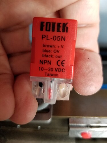
This is what I have on my 6445G. All three wires direct to the controller

Blue to GND
Black to the respective Limit negative
Brown to PUxy

Was wired like that from the factory and it’s been running for four years.

Sorry, I guess I misunderstood, you mean you have the same ones that Jack was talking about? Your photos aren’t loading but I am assuming based on your wiring convention, that you are running the hall sensors.

Red NPN block labeled PL-05N, 10 - 30 VDC

So you are actually pulling power from the Puxy for the sensor then?