Ortur LM3 w/ rotary thinks a 1 inch square is 1.25 in

Hi everyone! Long time lurker 1st time poster.

I recently got a new ortur LM3. It works great normally but I am having problems with the rotary.

I believe I have the mm/rotation and roller diameter correct because when I make a 1 inch x 1 inch square in lightburn, it will come out the same on my tumbler… but when I make the 1 inch x 1 inch square and try to line it up with the laser position button, the laser travels about 1.25 inches instead of stopping at my 1 inch mark.

I cannot figure out what is causing this and have tried everything I can find online . Any help is appreciated!

Thanks!

1 Like

Also a little more info, I am using the ortur roller rotary not a chuck. I am coming from an original ortur LM2 (not pro etc) and never had these issues.

The same goes for trying to make a line around the entire cup. The tumbler is 11 inch circumference. If I make an 11 inch box, the laser will travel about 13 inches on the cup or 2 inches past my mark. But when I actually do the engraving, it is basically the correct 11 inches.(think I still need to reslly fine tune the mm per rotation)

I have upgraded lightburn, upgraded the laser firmware and rebooted and played with the mm per rotation many times and this is the best I can do…correct engraving size but wrong dimension on screen.

Again any help is appreciated. Thank you!

Is it possible overscanning is involved?
If it is on, try turning it off and give that a try.

Overscanning was on but I know I’ve always had it on. Anyway turning it off didn’t help at all. Thanks though!

If anyone ever finds this looking for answers. SOLVED!

Well I’m an idiot, and as always!!.. It does come down to “mm per rotation” (aka steps per rotation? I dunno my lightburn says mm per rotation) and it is much more fine tuned than i imagined. It really really helps to have a digital caliper to get the exact roller dimensions as well. I was using .80 In before with my LM2 and it work great. Now I needed- .777

Also, for the mm/rotation it is amazing, In my case (ortur LM3 with I believe 1st edition ortur roller rotary but it might be the same as the current one available) how small incriments make a very huge different.

63.75 mm per rotation vs 63.88 mm per rotation was like 3/4 of an inch in movement on my cup/rotary? Sorry I’m canadian and can work with metric and imperial!

Cheers whoever!

1 Like

Very interesting. Thank you for posting your solution. I am surprised by the sensitivity and grateful for your analysis.

1 Like

A difference of 0.2% doesn’t sound like much, but a four inch mug has more than a foot of circumference, so a mere 0.2% works out to … nearly an inch.

(Despite being 'Murrican, my home shop runs on metric and is much the better for it.)

Haha yes I recently learned from a cabinet maker how much better using metric is. Room for less error for sure.

Despite me saying solved, I’m still have a decent number of problems. Having a hard time getting the mm/rotation right and whenever I think I have it my next engraving will start and end slightly off. Then it seems sometimes when I change settings they make little to no difference and other times they make fairly large location errors. I feel like it’s a roller size problem now too?

I do have a new roller in the mail so maybe it will help me but I don’t think anything has changed and I’m pretty sure my roller has the same motor as the new ones. From my understanding there is no reason the older roller shouldn’t be compatible, but I wouldn’t be surprised if it isn’t either.

Thanks everyone!

In original manual at page 46/50 is wroted, that man should change $101 variable from 100 to 80 when using YRR. Perhaps the authors have forgotten to recalculate correctly and according to this change the value in manual ? Worth answer from the creators…

Best is to measure the circumference (C) of reference object, leave the OLM3 draw one line at 0 and other at (C) and then after measuring difference adjust the value, and let OLM3 draw another set of lines… Until You find best value ?

The rotary’s speed and acceleration values may be too high, causing the mug / sippy cup / tumbler to skid, either slightly or greatly, as the roller turns.

I have no relevant experience, but reliable commentary indicates dialing the acceleration and speed down by large factors can dramatically improve the results. If an achingly slow speed works, then you’ve captured the problem.

but still is valid that 1.25 x 0.8 = 1 - according to the subject of this case… :slight_smile:

if You leave 100 in $101 - then it will have 1.25 length… (should have, we see it can be 0.777 ?)

worth testing on My site - will report later…

Well I kinda give up…

Thank you everyone who tried to help! I put weight in the cups, was kinda getting somewhere with the $101=80 code but still cound not get everything to line up. Played with the mm per rotation and roller diameter forever.

The best I can do is keep $101=100…in this case my logo I want to be 3.25 inches travels about 1/2 further on the cup. If I move the laser to where I want the logo to end, I can then squish the image in light burn to be 2.62 inches and it will come out at 3.25 inches in the cup.

Doing $101=80 enables me to line the cup up properly in light un, but it still prints to small. Changing the line spacing or roller diameter only seems to cause the engraving to start in the wrong sport and still count get dimensions right.

So I dunno, this works ok for me. I can line up the top, bottom and right side and just squash the image to align the left.

Cheers!

Would you be willing to share pictures of your efforts?

Rescaling the rotary axis to make the graphic work may have moved the start point.

I’m going to take some time to review this thoroughly because I feel you were really close to solving it or about to discover a systemic issue that’s causing problems for others.

Either way, I’m very grateful for your efforts.

Ugghhhhh, pretty much disregard everything I’ve said so far ecause I get things right at one dimension or for a couple runs and when I think I’ve got it I get back to square one.

I did figure out that the LM2 defaults to x=80 and y=80 and the LM3 is 100 and 100, so Ortur does require you to do the $101=80 code, but I still can’t get it right.

For some reason my brain hurts to much to figure out how to edit my old comments, but this is NOT SOLVED.

To make matters worse, I plugged in my old ortur LM2 to try to actually get some yetis done and now its acting exactly the same. Even though I know I have the same setting I did prior to getting the LM3.

I also deleted lightburn pref files, deleted the LM3 from devices, reinstalled the LM2 and I’m the same place I started essentially.

If anyone needs me I’ll be pissing in the wind!!

Random pointless update.

I played around with my LM2 for 4 plus hours tonight and got nowhere! Over the past few days i thought it was maybe the LM3 itself but now I’m just so lost.

I am not a tech expert by any means, but am very very far from a mom who doesn’t know how to work an iPad incompetent lol. This LM3 is only my second laser, but I was able to get the LM2 dailed in to do whatever I needed, to exact dimensions… Now I can’t get either to work (with the rotary, normally with x & y axis both are fine)

Well, I guess so much for yeti engravings! For now at least. :person_facepalming::person_facepalming::person_facepalming::person_shrugging:

Like I wroted - I write later My findings - and here they are. In short - it works like expected. :star_struck: :heart_eyes: :innocent:

Long version follows:

0./ My recommendation is to center the laser head before enabling YRR switch to the middle of working area so You have enough room to put objects there later
1./ don’t forget to disable homing $22=0
(be careful because it collides with $606 - homing by powering on the device - they cannot be set both to 0 at My device - some warning appears, also I used $22=0 and $606=1)
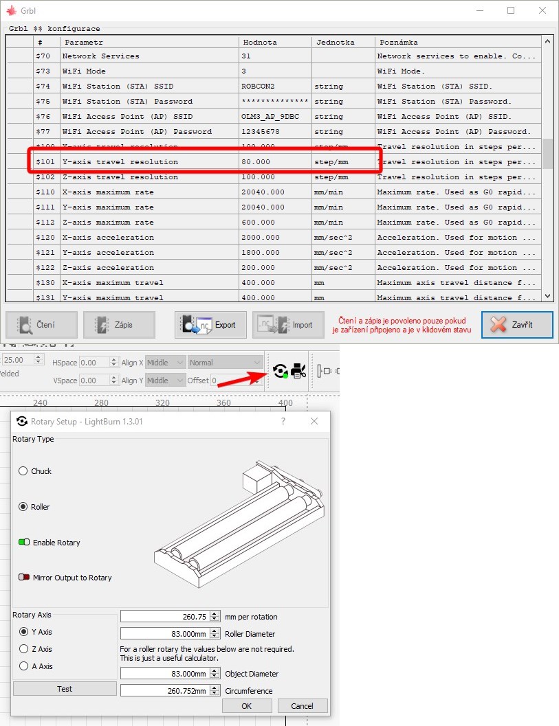
2./ YES, $101 should be 80 by OLM3.
3./ (not sure) but don’t forget to set-up the roller properly in LightBurn. I have done it.

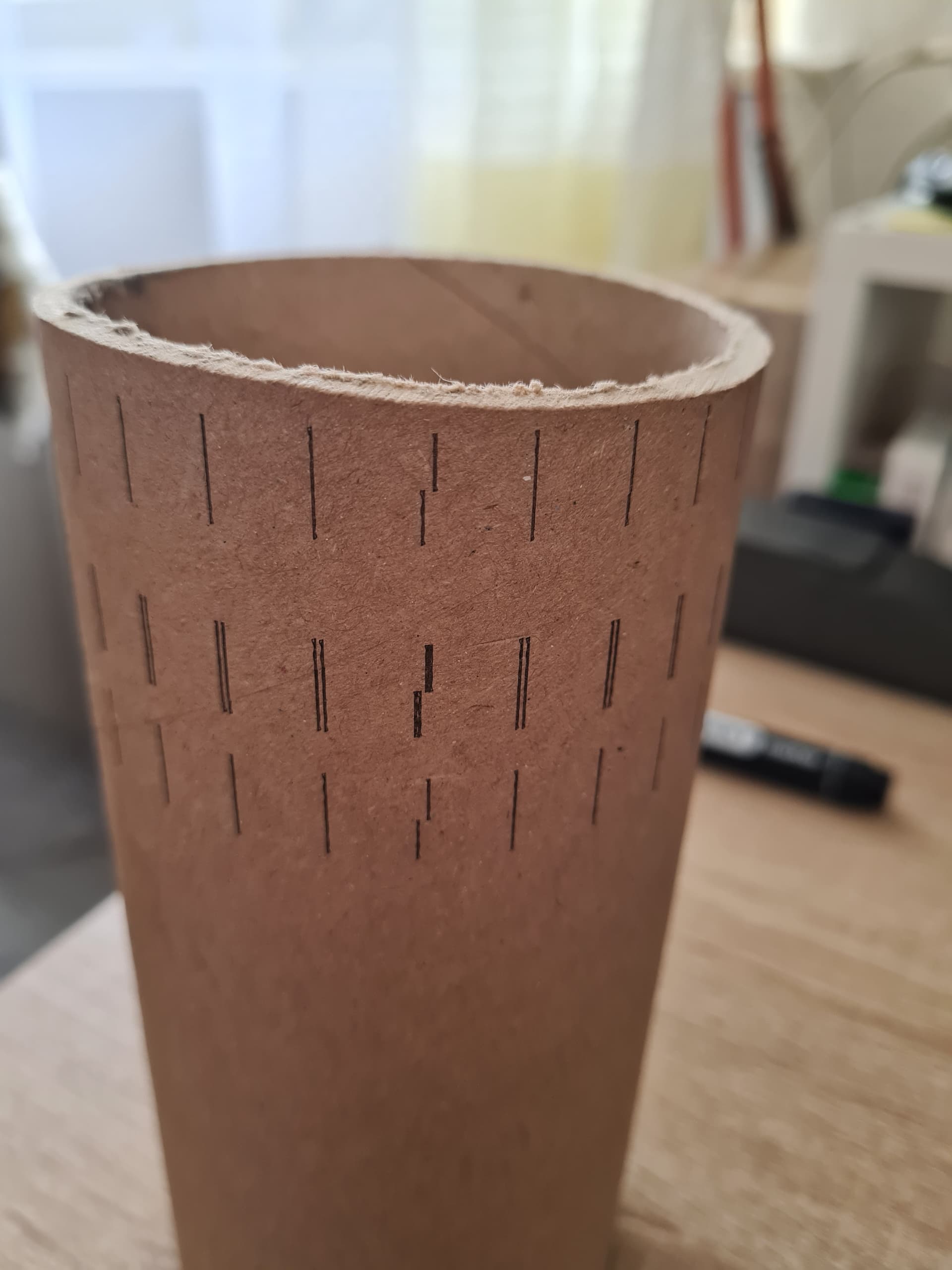
I have used some paper tube (from plotter paper roll). Very thick paper. Hard to cut :slight_smile:

Idea is simple. By diameter 83 mm of this tube should be the circumference 260.75 mm. That also shows the rotary setup screen when You fill in the diameter of the object and rotation length.

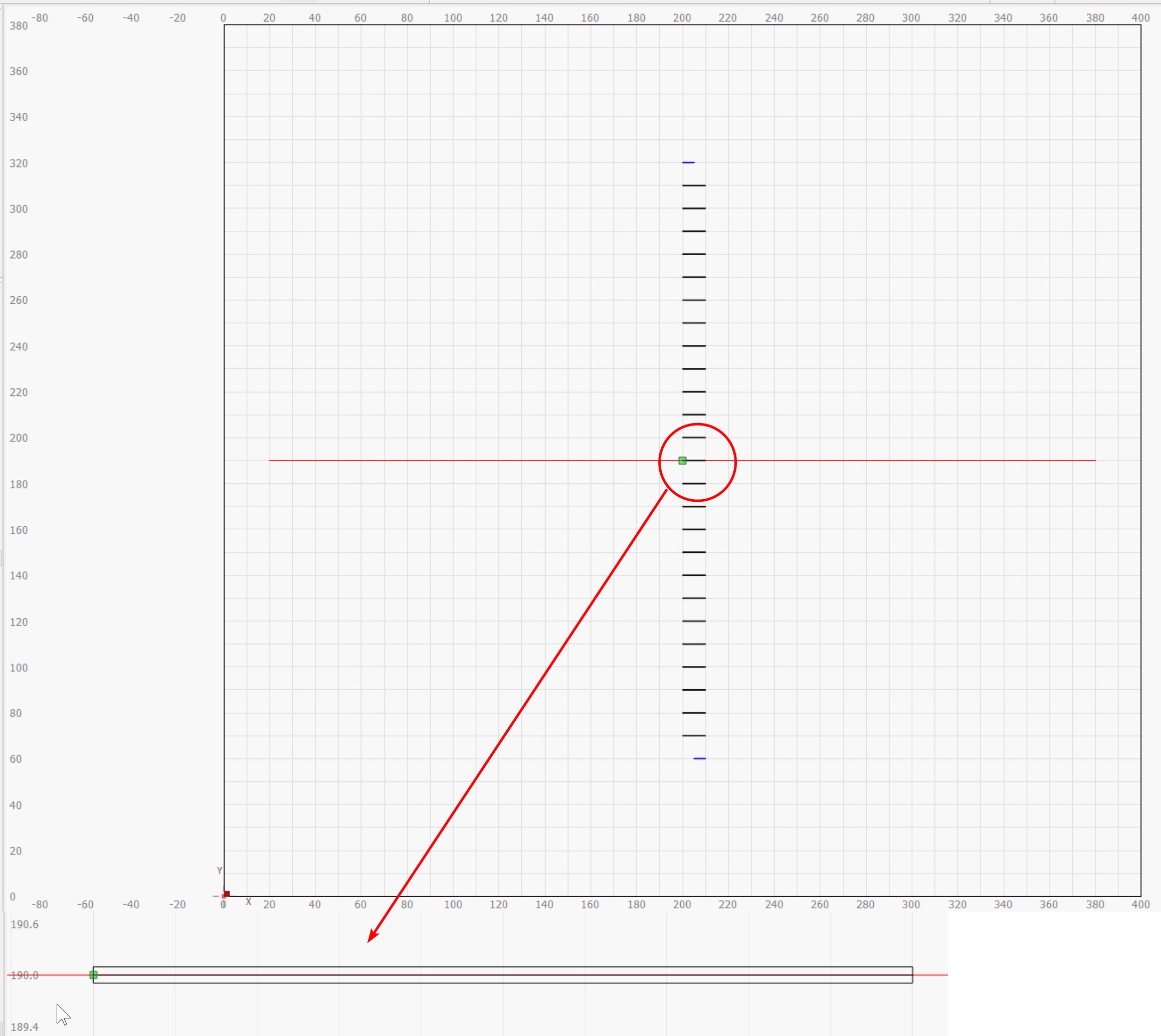
I was thinking - first I draw horizontal line through whole object in X direction - this will be the reference for future experiments - something like center line. OK, done quite easy :slight_smile: Has hidden the layer.

Then I drew one small horizontal line 10 mm from centre to the right. To say exactly - one line with 0.1 mm offset line in both directions (for better viewing).

Then I made 13 copies to +Y direction and also 13 copies to -Y direction - 10 mm distance - with array center to center - of that small line. This should give us 260 mm distance from bottom to the top.

At the highest line I have shifted right end 5 mm to left and at the lowest one the left end 5 mm to the right. This should precisely show the lines at the ends.

Like You can see on the photos, all went perfect - the distance between the two shortened lines is about 1 mm - it should be 0.75 mm.

I think with the knowledge of all variables in this game (precision of measurement of the tube, imperfection of the surface rolling on the rotating cylinders, and other factors) I can say it went PERFECT !

If You ask, why I have Ymax 380mm, it is because I have ZLD mounted - and I think better is to loose few milimeters than damage device. I have opened ticket about that, but the answer from ORTUR support was, that correct is 400. I think that is not correct. Everyone should ask themselves and answer also… If I move the two screws like in manual is shown at page 24/50 - section 4.2 - I automatically loose the distance between them. It cannot be simpler. I have thought about perhaps some automatic software correction, but this requires some switch to be enabled in the software - so the LightBurn is aware about the fact, that the ZLD is used… And there is none… Otherwise You bump into far end really hard…

Mind and sense save Your devices ! :smiley:

Hope You have same luck by using Yours YRRs. Let Us know…

Late to the thread but

Did you change Y steps from 100 to 80 as instructions?

YRR and Y motor are 1:1
So there should be nearly no need to use rotary wizard at all

Well I suppose I will call this solved. I really don’t know what happened initially, after playing around, changing to many settings, uninstalling lightburn, and going back to basics I have figured it out.

I suppose it all came down to $101=80 and mm per rotation. I just find it strange since the when you open the laser and “read from controller” itdefaults to $101=80 anyway.

The only thing I found out for sure if that the caliper measure did not correspond to the measurement I needed to get dimensions right. Caliper read - 0.777 in, once I move it to 0.8 inch I had better luck.

Also!.. after I finally got everything figured out Dimension wise I could not get the laser to fire the appropriate power. Though my motherboard was screwed but both my lasers were doing the same thing.

Turns out under - Edit-device settings-s value max. Was changed somehow. In console settings, the $30 code needs to be the same as S value max in device settings! Probably rookie stuff to most ppl but news to me!

Once again thank you to everyone for the help. This community is amazing!!!

1./ Final note about settings - they sometimes don’t get written into board - always “re-check” by disconnect->reconnect and reread the values… You may think You have changed (yes You have) but the writing didn’t go like expected. Only for to be sure :wink:

2./ Don’t use digital caliper if You unsure about readings (or want to be sure for sure) - instead use simple manual caliper with lasered gauges. I have had problems with them - because of battery or so. Cheap PRC crap… :smiley:

2023-01-22_06-26-09_firefox

3./ One time I had also problem with laser power, but it has been solved self after disconnecting the cable (going from top near air inlet) and reconnecting. I have asked ORTUR support how to measure what power is drawn from board but without answer for now, perhaps I will do sometimes self finding where to put some external A&V meter - something like this one or similar Ampermeter Voltmeter Digital. It wolud look nice mounted somewhere - and, You don’t need to check the power everytime by cutting some cardboard…

If someone has done this already please share details… :wink:

This topic was automatically closed 30 days after the last reply. New replies are no longer allowed.