First off, I apologize for not having a picture to actually show the “finished” item but I dont have my phone to pc usb cable with me at work.
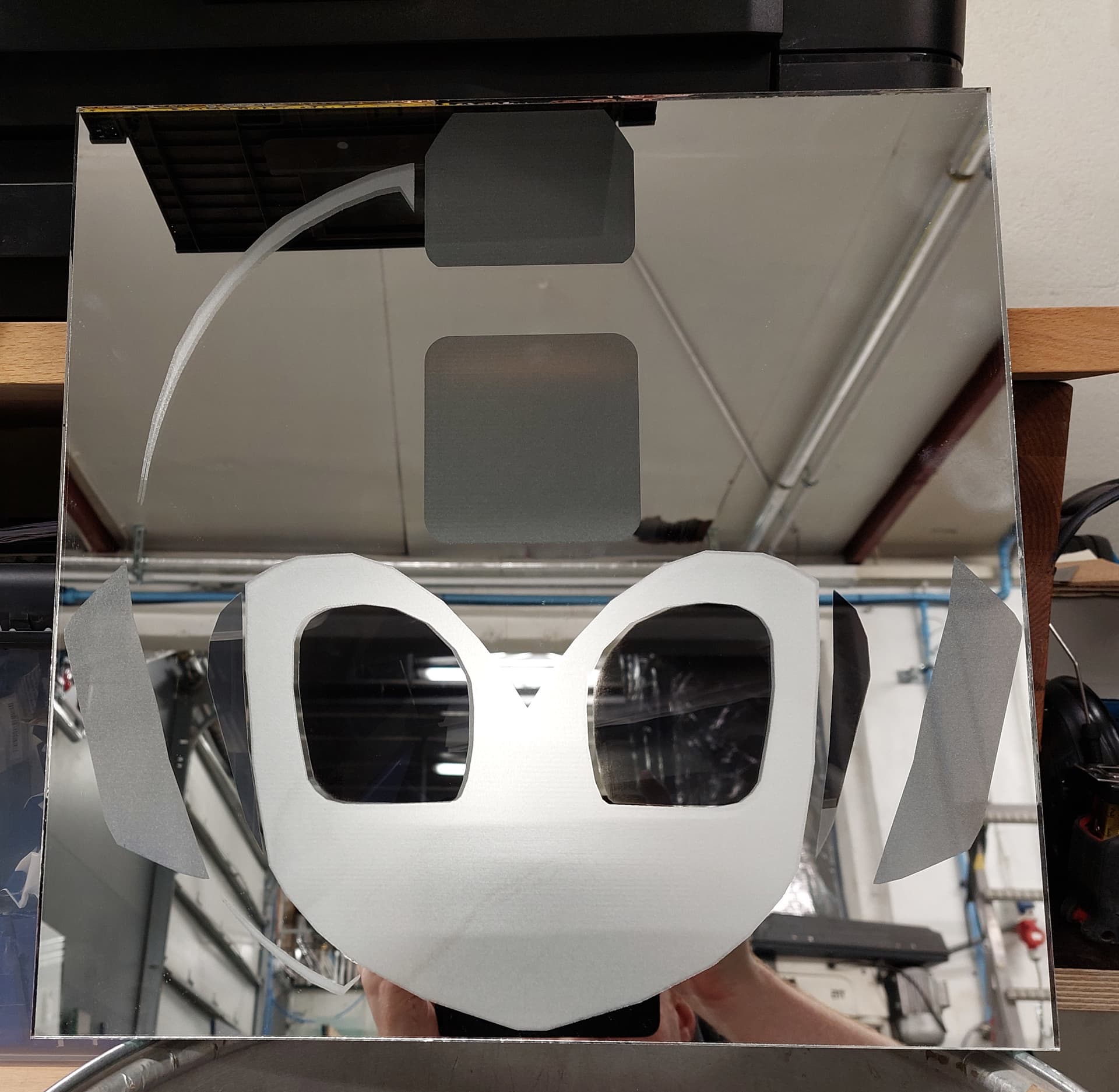
I am trying out a few things, see if they are something that works, this in particular making a laser engraved image on a mirror with diferent textures to the glass. The textures themselves, are working wonderfully but the output doesnt line up as it should…or at least how I believe it should.
thiis is the projet file, in it each layer is set up to output slightly diferently depening on where its hitting. In this case, layer 11 is hitting the front, the actual mirror part of the mirror, wheras the other two are hitting the back. layer 10 goes all the way through the backing material to produce a nice frosted glass effect, wheras layer 12 allows me to access the reflective material, and with the assist of …what I am pretty sure is the local equivalent of rubbing alchohol and steel wool, turns it into clear glass., giving me three lovely texture options on the mirror.
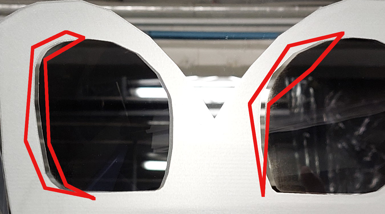
The issue however is that the front facing layer doesnt line up properly with the other, being something like 3mm further to the left then it should be to line up perfectly.
the material I am engraving on is a 380 x 380 mm pane of mirror, and I do one side, the flip to the other and…it doesnt work as I think it should.
Cool project. Can you describe the process you’re using to ensure alignment when you flip over the mirror? Please describe what you’re doing on the mirror side as well as the software side.
Also, to make sure I understand, are you saying that the entire layer is shifted to the left but otherwise perfectly shaped or is this a sizing issue as well? I’m not following how in your marked diagram why the issue would only be on one side but not the other if this was strictly an alignment issue.
I have a fence set up that I cut with the laser, so I have solid 0 point to work from. as such I simply start by putting the square mirror pane in the corner, engrave the top side first, then once that finished flip it, and again, put it in the corner and engrave the other layers.
I am …admitedly not sure how to better explain this.
oh right sorry.
the size is right where it should be, so thats not an issue, it seems to be entierly that its just …moved to the left.
as for flipping the image, in this particular case I did nothing as, aside from the helmet edges that are on the left, the entire thing is mirrored down the middle.
the tool layer I have set up is set up to be the exact size of the material I am using, and the bottom right corner of it is my effective 0 point for both x and y movement.
I think I’m following you and don’t see anything inherently wrong in the setup or in the file.
Just to cover some bases:
the file shows absolute coords, is that what you’re using for both sides?
are you making any manual moves of the laser head between operations?
I assume you’ve taken measurements but have you confirmed that it’s layer 11 that’s off and not the other two?
which side of the mirror are you engraving first? I assume the back since you believe it’s the second burn that’s not aligned. What happens if you reverse the order?
Is LightBurn controlling the job or you’re controlling it from your device controls?
yes I am using absolute coords on both, the only mnual moe I make is to move the bridge so I can acces the mirror and flip it, then I set it to do the next round with the other layers.
And checking it, yes you are right in that it appears to be layer 11 thats moved and not the other ones.
On this run I started on layre 11 and then did the other two afterwards, I have no yet tried the opposite on this version of the file (I previously tried it but with a really crappy trace job of the image I used)
Is it always an issue with layer 11 regardless of which side of the mirror you start with? Not sure if you’re able to say given the older version of the file. If so, that’s really odd.
Right now based on your jig setup I assume you’re able to reliably get perfectly positioned burns on other jobs. Can you confirm?
And the way you’re running this should act essentially as 2 independent jobs.
The only thing I can think of is that you your jig alignment is actually slightly off to one side and that you’re seeing the cumulative effect of that when done on both sides. However, since your measurements indicate that it’s only layer 11 that’s off it doesn’t quite fit.
Can I suggest that you retest your jig alignment and ensure that it matches your work boundary?
right, after a couple of smaller (faster and less wasteful) tests I do seem to be getting the same result of layer 11 being shifted by about 2 or 3 mm, no mater if I do layer 11 first or last.
This is still immensly puzzling but, obviously something I can simply work with and compensate by moving the trouble layer right by those same 2-3 millimeters, but that doesnt really change how odd it is, to me, at least.
This is truly odd. Maybe one last test, what happens if you burn all layers on the same side without flipping (but keeping to the same number of burn cycles). Do the layers then align? If so, that would imply an issue with the alignment process.
Don’t know where else to take this. Maybe one of the LightBurn guys can provide some insight.
It’s ‘hole’ is 0.5mm larger (width) to be able to get it in and out. I usually lay the separator sheets on the steel bed and that makes it a little more snug.
I haven’t ‘flipped’ it like you, but have taken it out and tried to recover with just the jig for alignment. I could easily see the meeting line. That is on one of my tight fitting jigs.
I’ve had better success with metal parts for alignment. Keep in mind that if it’s off 0.5mm in the jig when you flip it, you’ll be at a mm.
Couple of questions.
What is the ‘image’ layer that is turned off?
I got it selected, but couldn’t understand the purpose.
How do you go to absolute 0,0 and engrave anything since there is no way to reach engraving speed at 0, 0? Should give you the dreaded ‘slop error’…
I haven’t been able to get what would be a proper Jig to work on the machine I am using at work, as its more of an industrial piece then anything. …and largely been teaching myself so its entirely possible I am making errors all around.
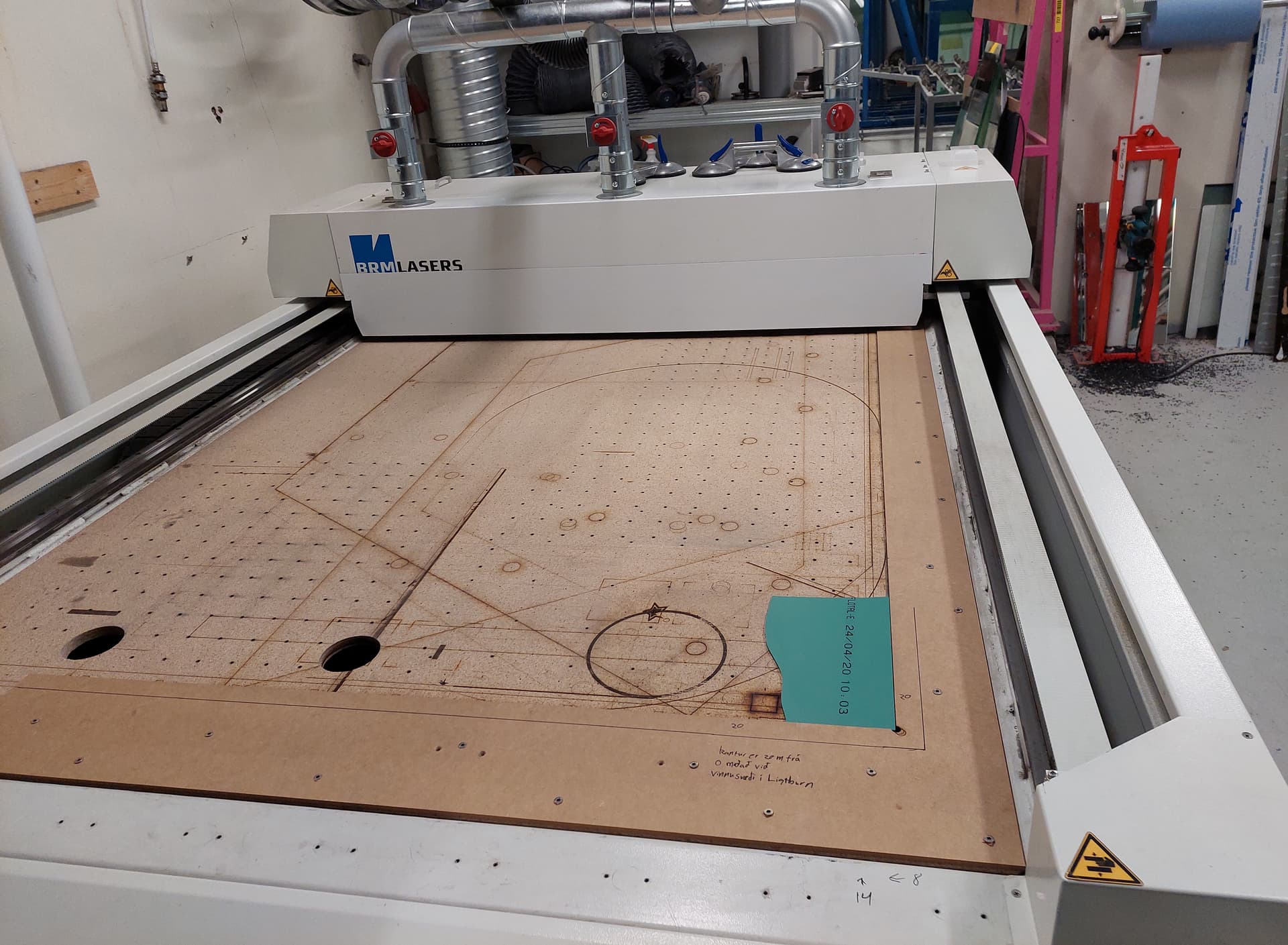
I am using this absolute chonker of a machine, and we had to replace the bars it came with with a …I forget if the word is plywood or particle board, language barriers in odd places, as the sharp edges would scratch the glass.
The image layer is the image I used originally for the design. I made a first attempt with Trace image but I wasnt happy with it, and the computer I use at work is perhaps not the most powerful for making the fine tuning of the tracing work. I purged those layers and traced the shapes manually, and adjust them slightly so that most of the image was a perfect mirror across the vertical. its mostly just there now because I didn’t throw it out.
as for the absolute 0, the fence …or Jig, as the word might be, is cut at 20mm from where the machines absolute 0 is, so its my “working” 0 point. …I am pretty sure I just didnt explain that correctly.
Are you saying English isn’t your first language? If so then you had me fooled.
Once you’re able to run your test burns on the same side that will pretty quickly tell you if you just have an alignment issue. The question then would be why do the back layers appear to be aligned onto the mirror. Perhaps a difference in measurement of your actual mirror dimensions vs your tool frame.
I thought of one other possibility. Is it possible that your laser is not calibrated correctly and is engraving either bigger or smaller than design size? If so, then you may have gotten the initial jig alignment incorrect so it looks right on one side but not if you flip it. I’m trying to decide if that makes sense in my head.
Suggestions if it comes to that:
measure mirror size to verify it matches design dimensions
test burn shapes of specific size and confirm actual measurements.
nope, second language. mostly picked up as a kid from way to much tv and video games but I always run into the odd word that is just either doesnt translate to my native language or vice versa or is just one of those words I never heard before.
Ok, just to clarify… I use absolute coordinates when I use any of the jigs I’ve made. I engrave the absolute offset into the jig. That partial 95 is the X displacement on that particular jig.
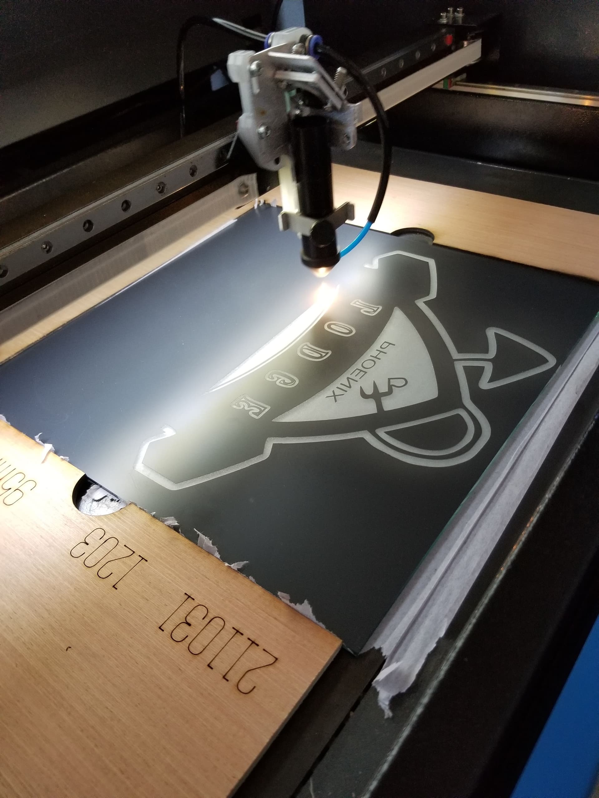
Back at work so back at the laser.
Did a minorly modified test , with the eyes shrunk by 10% each in order to be able to tell if they were aligned or not with all in the same layer and same burn.
Near as I can tell its exactly as it should be all things considered…which of course doesnt explain the alignment not lining up.
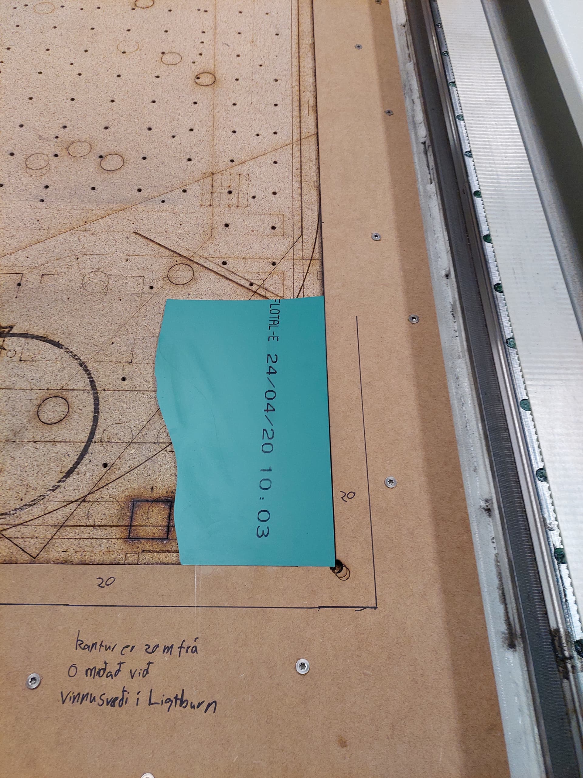
Following is a picture of the machine I use and its setup…moe or less, and the fence, or jig I have set up to work with.
the visible marker line was more or less where I knew the absolute limit of the head movement would be, so I knew where to safely screw the thing in place.
Okay. Interesting. So does imply an alignment issue still or possibly a scaling issue.
2 things to try:
If you put your material into your jig and run a frame operation around the tool boundary that you created in the design, does the laser trace perfectly around the perimeter of the work piece? It has to be dead on. If it’s off by 2 mm left or right then that would account for the issue you’re seeing.
Did you have a chance to test some burns of shapes of known size to confirm that your laser steppers are calibrated?
These are the last 2 things I can see as potential issues.
oddly enough my workplace had decided to get a machine long before I started here and I just kind of …wound up being the laser guy, since it was placed closed to where I was working and INTEREST in the cool machine that does the laser and whatnot.
Because of timing (again) I will have to test that tomorrow, see what happens.
in regards to the second question …I dont think so no.
The simple square/ rectangle shapes I have been doing for the most part seem to be accurate to the size and placement as far as I can tell …though an issue I have noticed and not really had a chance to do anything about is that past a certain point on the Y axis it seems like a couple of millimeters vanish…which might be the steppers not being calibrated correctly.
A lot of this comes from not getting the “guy” from the company to instruct when we set it up because of the covid, and quite frankly some I am sure, hamfisted hasty attempts at calibrating the lenses at the start which might have left us on the backfoot while trying to get everything right.
I cant even tell you how much time it took me to get third mirror to align correctly because the machine just having certain “not allowed to test if X” issues.