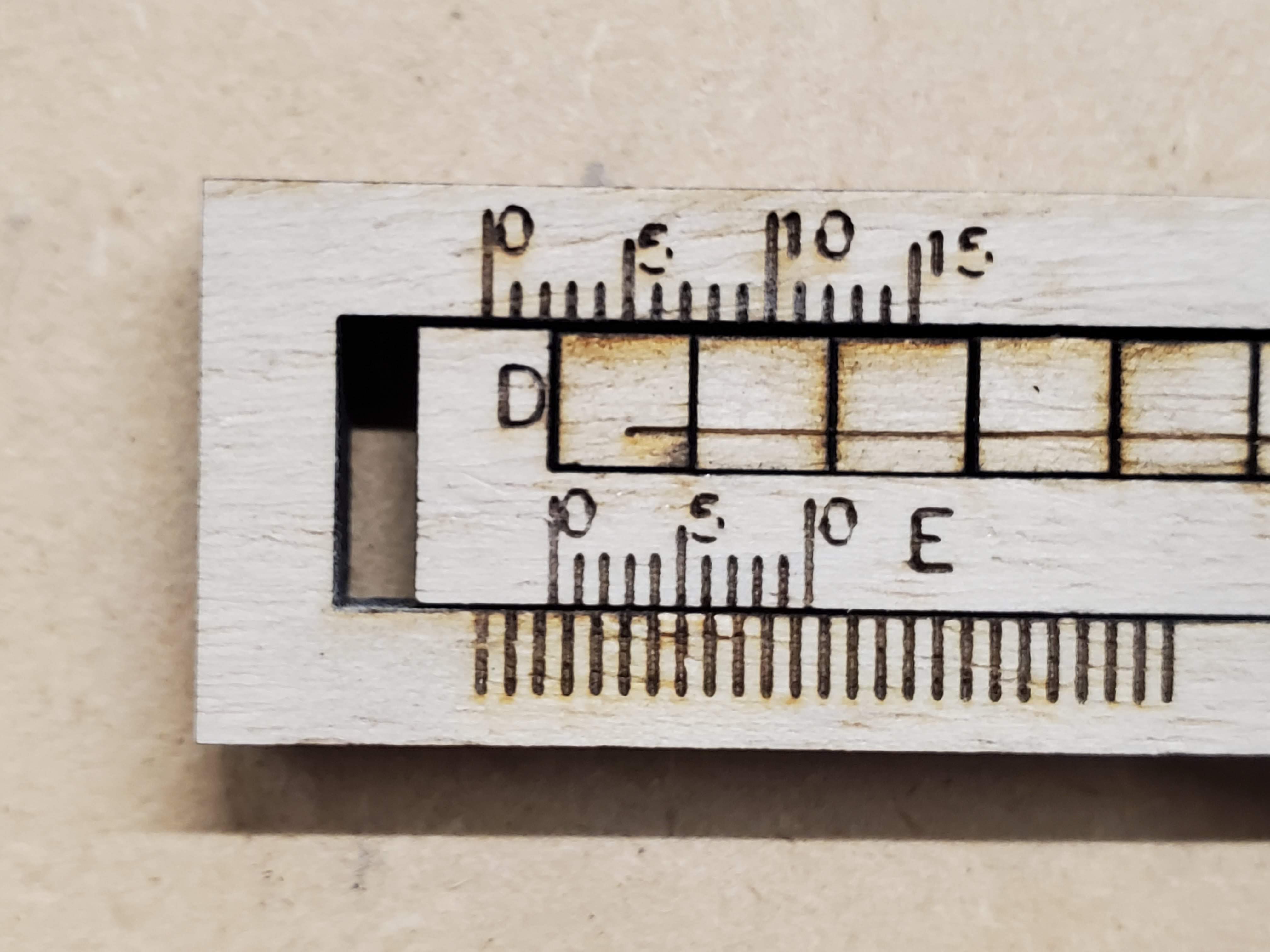
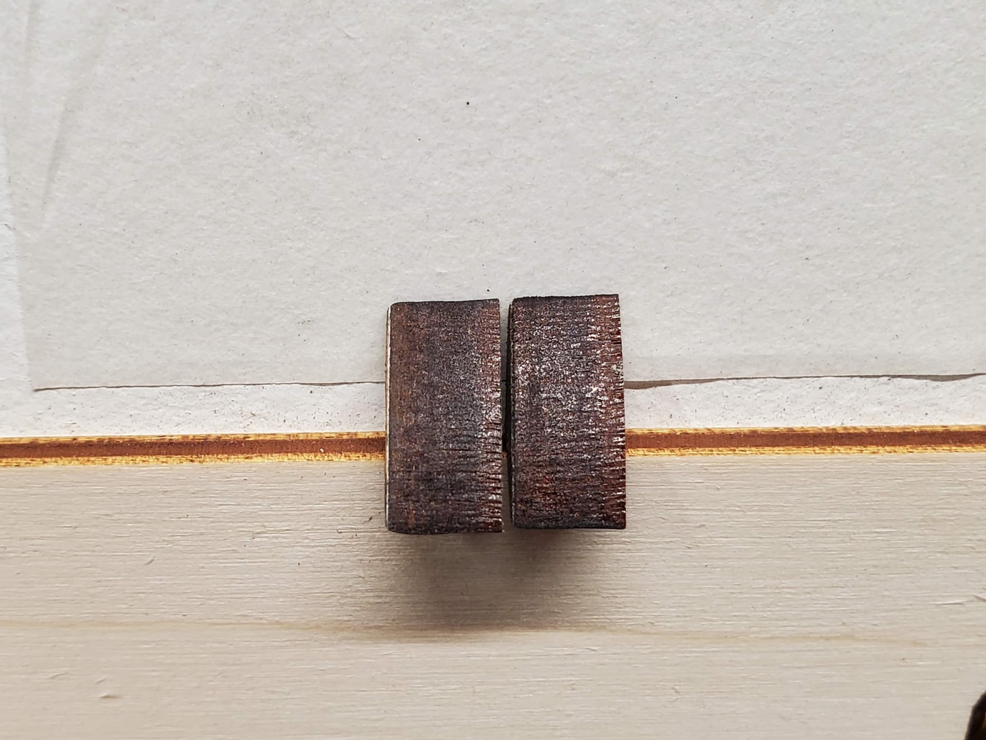
Here is the image of my kerf test. Based on the numbers it looks like I am at about 0.125mm. Am I looking at this correctly?
Hi.
Wow, the marvels of modern photography ![]() .
.
I for one assumed at least twice that.
That IMO explains the surface roughness of the cut, but not all of the jagged edges.
Yes, that’s AFAIK the general word for the structure that rides on the rail(s).
There are plenty of variations of those structures, especially in more budget oriented equipment.
Most, but not all are adjustable.
On the plain bearing variety, there’s usually a wedge -or a cone in round ones- that can be moved to adjust the play.
On the ball- and roller-bearing variety the methods for adjusting the play vary even more.
On some -like xTool D1- there’s three concave surface bearings, one with an eccentric fixing point riding on each rail-pair, and the play is adjusted by rotating that bearing.
Etc, etc.
The ancient Chinese proverb, stolen and popularized by Kodak, works wonders in this case as well ![]()
Nope, not belts, but they do have their role in this as well.
The belts are often overlooked badly, and the tension tend to be as often too tight as it is too loose.
The beotch of it is that without a spring scale, and a precise method to adjust the tension in the said machine, it’s pretty much a trial and error type of thing.
With the shorter (~400mm or so) span belts, the ability to rotate the midpoint of the belt 90 degrees is a good place to start.
On longer span ones, just the “feel”…and trial & error ![]() .
.
Too loose, and all sorts of backlash problems occur, too tight and something starts to vibrate sooner or later.
That will probably help a lot, or at least allow more experimentation.
Regards,
Sam
![]()
1 Like
As long as the lens is still secure?, a loose focus lens will cause poor results. I wonder if you are getting enough air flow? Instead of trying to move the nozzle closer you may want to consider upgrading your air supply especially if you are primarily cutting MDF and wood products. A decent flow of air is needed to clear away the smoke and residue and allow the beam to penetrate better.
The power fluctuation will only really happen in the very last few mm leading in and out of corners - where it is needed, so for cutting generally the Min should always be lower , to whatever looks best for the corners and still cuts through, try about 30-40% less e.g. 60/85
Have you tried going much slower like 12mm/s with 50%min and 60% max power?
Have you tried a wider range of speeds and powers using the material test?
For example:
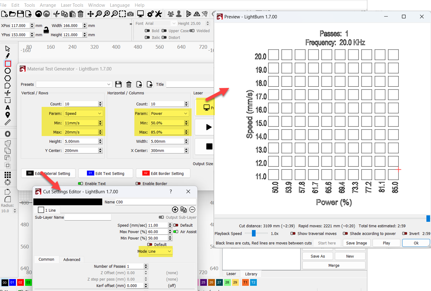
Try focussing to the surface of the material instead. MDF has a harder skin due to the heat pressing process so it’s more important for the laser to quickly break through that top skin to allow the beam time to get through the rest of the material.
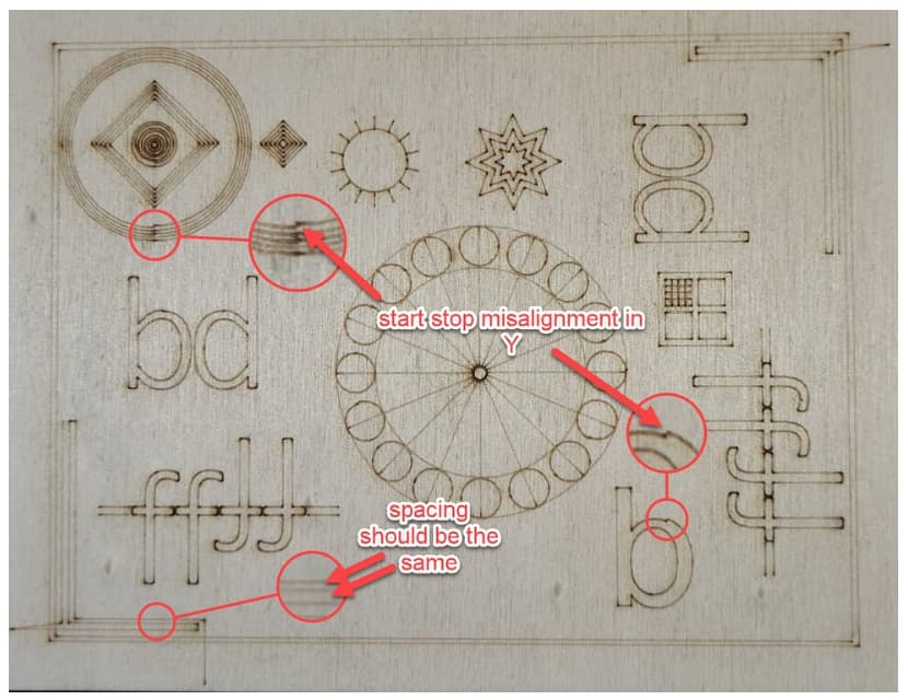
Regarding backlash, the test file attached here is good at showing backlash issues and which axis are involved (please disable ‘Optimise Cut Path’ for this test):
Test.lbrn2 (73.5 KB)
The pic below is an example of what the test result looks like, in this case from a machine which exhibited some noticeable backlash in the Y-axis;
1 Like
I will have to research how to adjust the HIWIN bearings.
I have been looking into the spring scales. I know there is no specific tension to follow but I figure once I dial it in good I will know my tensions going forward. For now I have been doing a combination of the 90° twist and trial & error.
Thanks Sam for all the great info!
My lens is secure. I definitely could use better air flow. I figured I would try to get the nozzle closer to see if that would help but I did not notice any improvement. In fact I feel like there was more surface residue along the edge of the cut by doing this. I now have a filtered line from my compressor ran to my machine. I also have an air line ran to my laser head. I am going to do further testing with a blowing air across the surface to see if that helps minimize the residue along the cut. I can also test running that line into the air assist nozzle as well and see if that helps with residue and cutting. I may do a combination of both. We will see.
I generally do have a lower Min setting when cutting. But because part of my issues include dotted lines/not cutting through on the bottom side, I did not want to take a chance of that influencing my testing.
For the 1/4" MDF I have not messed around much with settings. I quickly found a setting that seemed to give me a decent colored edge and cut through so I went with it to start. It is that balance between cut time and machine power. I obviously want it to cut quickly but I also want to keep the power as low as I can so I don’t burn up the tube quicker. And to be honest, the power (75-85) is above my normal comfort zone. I have ran test cards for all my other materials. I should probably do it for this one as well.
I was not aware of this. Very interesting. I will try cutting from the surface today and see what happens.
I will run this test today as well.
Thanks for the info and the help Nicholas!
1 Like
Would be nice if Lightburn were to put a troubleshooting tab with some tests to identify different common problems such as backlash and limit switch triggering.
3 Likes
Although they do not have those specific tests available, they do have some helpful ones already. Maybe they can add those.
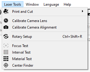
Adding some tests to identify common problems would I think speed up being able to help people when having problems and posting on the forum.
Openbuilds has a nice troubleshooter for open/closed switches.
2 Likes
I agree completely.
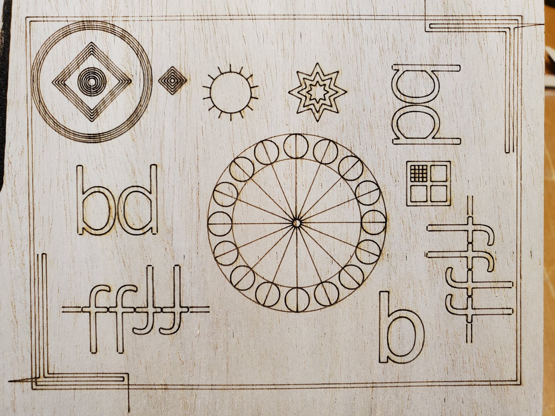
Here is my test. I am not sure exactly all that I should be looking for on this other than what is pointed out in your image. It looks better than I expected. How does it look to you guys?
Although I am a little perplexed on why the bottoms of some of the letters are missing their corners but not other parts that have similar corners?
So I started testing slower speeds with lower power. I kind of settled at the following (14/60/45).
Speed: 14
Max Power: 60
Min Power: 45
I would not say that I notice any differences in the cutting. Kind of the same as 20/75. But the power level is now down at a more comfortable range for me.
I adjusted the FP to the top of the material and ran some tests. Still no change on the main issue of the jagged edges on the bottom surface but the top surface looks MUCH better ![]()
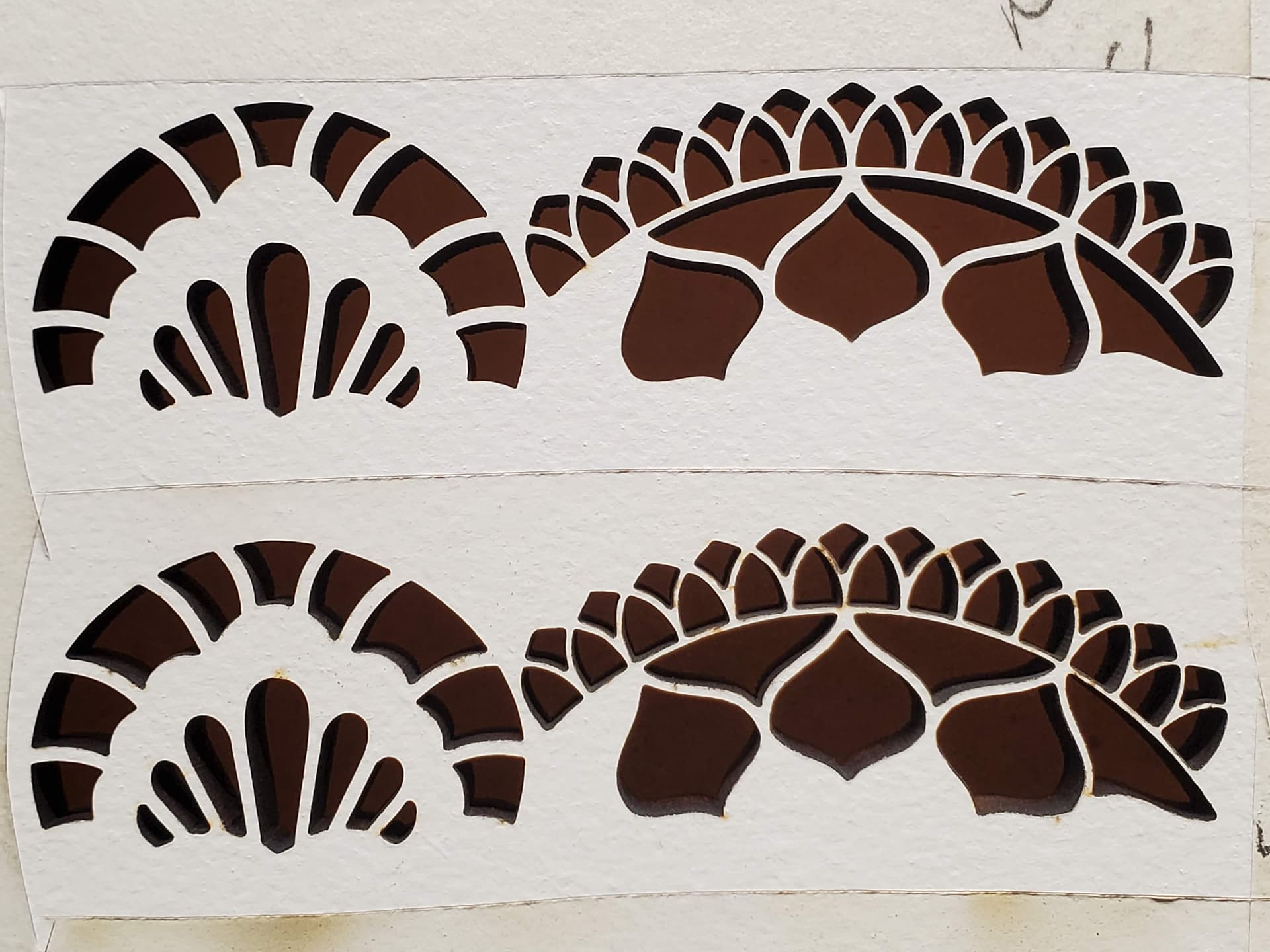
I tested my new air line from my compressor. I first setup the external flexible snake hose with a flat nozzle on it. I ran a bunch of tests. Although I think that it helped with surface residue, but it also causes the top edge to burn more before going out. This is not a huge problem in most cases but when you have tiny intricate designs with fine lines between holes, this can cause lines to burn through or become too fine which you can see in the comparison image below.
I also tested running the compressor air to my air assist nozzle instead and ran it at different pressures. So far 30-35psi seems to do a great job. This combined with focusing the laser at the surface produces an amazing cut with no residue getting under the transfer tape (as it has with all other tests).
Here is a comparison of the difference between using the external flexible air hose and running the compressed air through the air assist nozzle.
The rest of the settings are the same:
- Laser is focused at surface
- Speed/Power is 14/60/45
Notice the lines between the small holes. Quite a difference. These lines are roughly .75mm wide so it doesn’t take much to burn through them.
This is the back side of the last cut I did where the top edges were beautiful.
This is not a pretty cut. I would have to spend a ton of time trying to clean this up because it would be noticeable. I will do more testing with my power/speed/air to see if I can find a way to get this cleaned up.
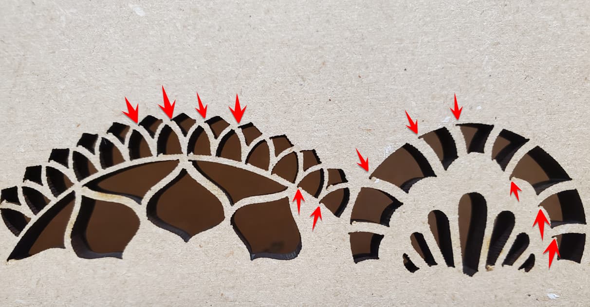
Also for some reason I am seeing a bunch of corners where the line seems to go beyond the corner (red arrows). Not sure what changes I made that would cause this other than more air assist pressure.
UPDATE: I realized that these corner issues were also happening on all other previous tests as well but maybe a little more noticeable after these recent changes. So it was not from what I did here. Not exactly sure what is causing it though.
The second thing I noticed after added more air assist pressure is the cuts do look way better. In fact I notice that the more pressure I apply the less shiny the cut edges are. I assume this is resin build up from the heat? And by applying the added air it cools the edges down much quicker causing less resin? This is nice because I do notice that the pieces will not drop out because of the resin build up at times. I think this was set at 25psi. Once I got to 35psi almost all the shine was gone. Unfortunately I had tossed these two pieces before the 35psi test ![]()
Anyway, it has been a good day so far of testing. I feel like I might be making some progress on dialing some things in. I just NEED to try and figure out the jagged edges on the bottom side so I can start making my pieces. ![]()
Hi.
There’s no mention about any adjustability in their technical documentation:
so there’s probably no way to adjust the play.
Those types of carriages -or the round rail varieties- usually don’t require or need adjusting during their normal lifespan.
The play is predetermined by the accuracy class of the carriage, and/or the rail.
The suspiciously similar NSK ones I have stashed away are non-adjustable as well.
Some fine tuning can be acchieved by changing the lubrication thicker or thinner, within the manufacturers recommendations of course.
Usually there’s no need for that though.
Because the tolerances in those rail systems are rather small, the installation can be very tricky and the rigidity and stability of the structure the rails are mounted on is very important.
One of the most important factors when a smooth operation is required is parallelism, 3.3.1.1 onwards on:
In systems with two parallel rails that has no tool loads (for example laser-, etc. cutting, printing, painting, etc.), one rail may be the dominant fixed rail, and the other end may have some mechanism that allow play if the parallelism doesn’t for some reason stay constant.
In any case, I for one don’t think that the issues You’re having are the result of play in the linear rails.
If the parallellism requirements are not met, there may be some binding happening, but without very precise measurements and measuring the friction of the rails over their whole travel, that’s impossible to tell.
Judging by this:
I for one don’t think You have backlash, binding, or play issues.
The missing corners You mentioned are indeed strange, but I don’t know enough about CO2 lasers or LB for that matter to even guess what’s the reason behind those.
I’m a DIYholic so if I need one, I make my spring scales from a suitable spring, a plastic tube, and a piece of stainless steel Tig- welding rod.
And calibrate it with known weights.
Once there’s a repeatable way to measure the belt tension in g:s/oz:s/ whatever units one wants to use, it’s easy to make a chart with the different tensions and their effects.
All and all, I’d say that You may have found and passed the accuracy limit of Your setup, and a perfect result in that scale is hard or even impossible to acchieve.
While the result isn’t probably suitable for Your needs, what happens if You scale Your design up, say x1.5 or x2?
If the result gets significantly better, the issue may lurk in the controller, drivers, or the stepper motors.
Or any combination of those.
Edit:
Or alternatively, scale the “backlash test” down, that’ll also reveal quite quickly if there’s accuracy issue if the results get worse.
Regards,
Sam
![]()
2 Likes
Not a Ruida driver and just a wild guess maybe changing the PWM rising edge to synchronize (or desynchronize)?
Maybe @jkwilborn and @ednisley can give something more about this idea.
1 Like
The typical setting seems to be False for both X and Y. If either are True, turn them off and see what happens.
IMO, that won’t change anything in these patterns, but it’s certainly worth checking.
1 Like
Yeah it is strange. In fact if you look at the 0’s and 5’s in my image of the other backlash test I did you will see some odd things as well. Notice all the 0’s have the same odd shape and all the 5’s are missing the same parts. Obviously my machine has an issue with text. Just what I need, another issue to figure out ![]()
Thanks for the info and the help.
I will check this. Thanks
After further testing I FINALLY feel like I am getting somewhere ![]() .
.
I did more testing with different speeds/power/air and finally found a happy medium. It is not perfect on the bottom side but it is acceptable . Unfortunately I settled on a speed of 13 which is quite slow. This means that for this particular project I will have about 75 minutes of run time which is quite a bit more than previously. But I am saving time in other areas. And I went from 85 power to 65, so I am not taxing the tube as much.
I also tested air pressure up to 60psi. I found that 55-60 psi works best for 1/4" MDF on my machine. Maybe I should test even higher? ![]() I just don’t know how much pressure my air lines/connections can take. I would hate for something to give while running a job.
I just don’t know how much pressure my air lines/connections can take. I would hate for something to give while running a job.
Here is the bottom side using 13/65/55 settings. Most of the pieces fall out from the air assist pressure.

Although the edges on the bottom side are not crisp or straight or that clean, they are quite a bit better than before. Of all the testing and things I have tried I noticed the majority, if not all, of the improvement came from adding high air pressure to the air assist nozzle.
After reaching this point, I ran one of my large intricate jobs and it came out absolutely perfect ![]() .
.
Thanks to everyone who jumped in for the assist. I am learning a ton from you guys.
A couple follow-up questions:
When I ran that job mentioned in my previous post I added double sided tape on the bottom side and I did not have to make any changes to the settings mentioned previously. Normally I would have to either adjust the speed down or the power up slightly. I thought for sure I would have to this time because I moved the focus to the top surface, further away from the bottom. In my brain I would think that the intensity of the laser would be slightly weaker at the bottom surface now. But maybe that has something to do with what Nicholas said about the harder skin that MDF has and by moving the focus to the surface it breaks through quicker? Or maybe it is the 60psi of air pressure cleaning the cut better? Or maybe it was the slower speed. Or most likely a combination of them all. Any incite on this?
Can someone explain why I am finally seeing some improvement in the jagged edges by adding the high pressure air? This whole issue has perplexed me from the start. It makes no sense how the top edge is perfect and the bottom edge is crazy jagged. What’s even more odd to me is I have had this issue on 1/8" and 1/4" material. That does not seem all that thick to me. I have always felt that something is happening to the beam after the top surface is cut, otherwise we would see on the top surface as well. What IS happening eludes me, but for some reason the higher pressure air seems to help the beam stay on track better as it cuts through the material. Any thoughts on this?
Just trying to understand and make sense of all this.
Thanks
I second that.
1 Like
Hi.
True, missed those the first time around.
These are once again one of those many things I don’t know nearly enough to offer any advice.
If I had to guess, on the 0’s there’s some kind of pulsing going on for some reason, acceleration/deceleration power compensation for example.
One dot and uniform width burn would make sense, two dots with reducing power burns make no sense to me.
The 5’s make even less sense, the curve is roughly the same as in the 0’s, but the result is completely different.
Fortunately, there seems to be a lot of folks on this forum who seems to be concentrating solely on marking/etching text and pics, I’d be suprised if someone did’t know the solution to that issue.
You’re welcome.
Great news ![]() .
.
If this was a poll, my vote would go to this.
Tldr:
A somewhat educated guess, higher air flow keeps the debris out of the cut, and nitrogen retards unnecessary burning.
The material most likely plays a role in it as well.
I can’t offer any hard scientific proof for it, but most likely that’s also a combination of a few things.
While seemingly high powered, the focused laser beam loses power fast when out of focus.
On “shorter lenses” it happens faster, on “longer lenses” slower.
So, thicker the material, the progressively harder it is to cut cleanly.
Until the beam doesn’t get through, just burns the material uncontrollably.
In theory, the laser beam evaporates the material, and produces an uniform trench/kerf.
The reality -especially with hobby lasers operating in active gas environment- is different, a good portion of the material is actually melted, burned and scorched rather than evaporated.
The liquid surface, and the burning byproducts and residue will reflect, obstruct and otherwise mess up with the laser beam.
The deeper into the material we go, the less is evaporated, more is turned (eventually) into solid particles.
Since we can’t use the max laser power to ensure maximum material evaporation all the time for very obvious reasons, the power vs. speed is optimized for any given material and task.
That sweet spot is often very narrow, and anything obstructing or messing up the laser beam will have an adverse effect on the cut.
High volume airflow helps in that in two ways, it keeps the obstructions at minimum, and the nitrogen reduces the materials tendency to burn.
And then there’s the material and it’s properties.
While MDF may look homogenous material, it’s most definitely not.
It’s a material made out of waste products, as cheaply as possible.
Always keeping as close to the legislation minimums as possible.
Just like @NicholasL said, the skin can be rather hard as far as the laser beam is concerned, and there’s actually no telling what the properties of the binding agent(s) is (/are), nor the properties of the fibers.
So, with some other MDF sheet or with some other material, the jaggedness of the bottom cut would most likely look different.
Better or worse, that’s very hard to know.
Regards,
Sam
![]()
1 Like