So true!
Thanks again!
So true!
Thanks again!
I see these are quite small. And cutting with a 90watt laser. You may be trying to cut a fine diamond with a chisel.
You are probably right. LOL. But I know it can do a decent job if I can work out a couple little issues.
A question on the smaller holes not always being centered. I understand the mechanics of why or how this happens. I know that coming in fast from one direction and starting a cut can be slightly different than coming in fast from the other due to backlash. My question is, is there a way to release that backlash from all sides before starting the cut? What if I placed a shape/pattern (whatever shape or pattern would release the backlash) centered over the small circle? Then set the machine to not fire for those shapes/patterns, and ran those shapes before each small circle?
My original thought was to do a slightly larger circle at a slow speed, so that it would not create backlash itself, before moving to the smaller circle.
I hope this makes as much sense in reality than it does in my head? ![]()
No, because the motion in one direction will take up the backlash in that direction and when the machines starts moving in the other direction, the head won’t move until the entire backlash is taken up.
Which is why circles are so good at showing backlash: the laser head must move in both directions on both axes, so no matter what you do, the backlash will appear somewhere along the circle.
The only way to get rid of backlash is to fix the mechanical problem(s). Clever software tricks may seem to work for the current pattern, but the next pattern will reveal the backlash in a different situation.
Yeah I tested the theory right before you replied and found it did not work. I just need to steer clear of the intricate jobs. LOL. I can do them on my diode but it has to run at 100% in order to cut 1/8" hardwood and go at about 10mm/s which leaves the edges a little too dark for my liking.
Thanks for the help!
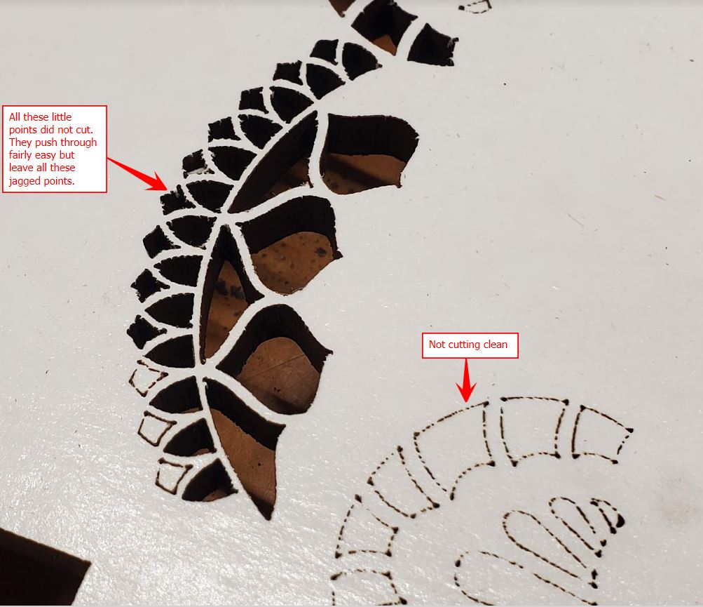
Well as some of you may have seen in another one of my posts, I am still having issues with the serrated/jagged edges that we thought was due to the kerf setting in LB.
Here are some pics of my most recent cuts.
This is the bottom side of the cut. It has super thin double sided tape on it.
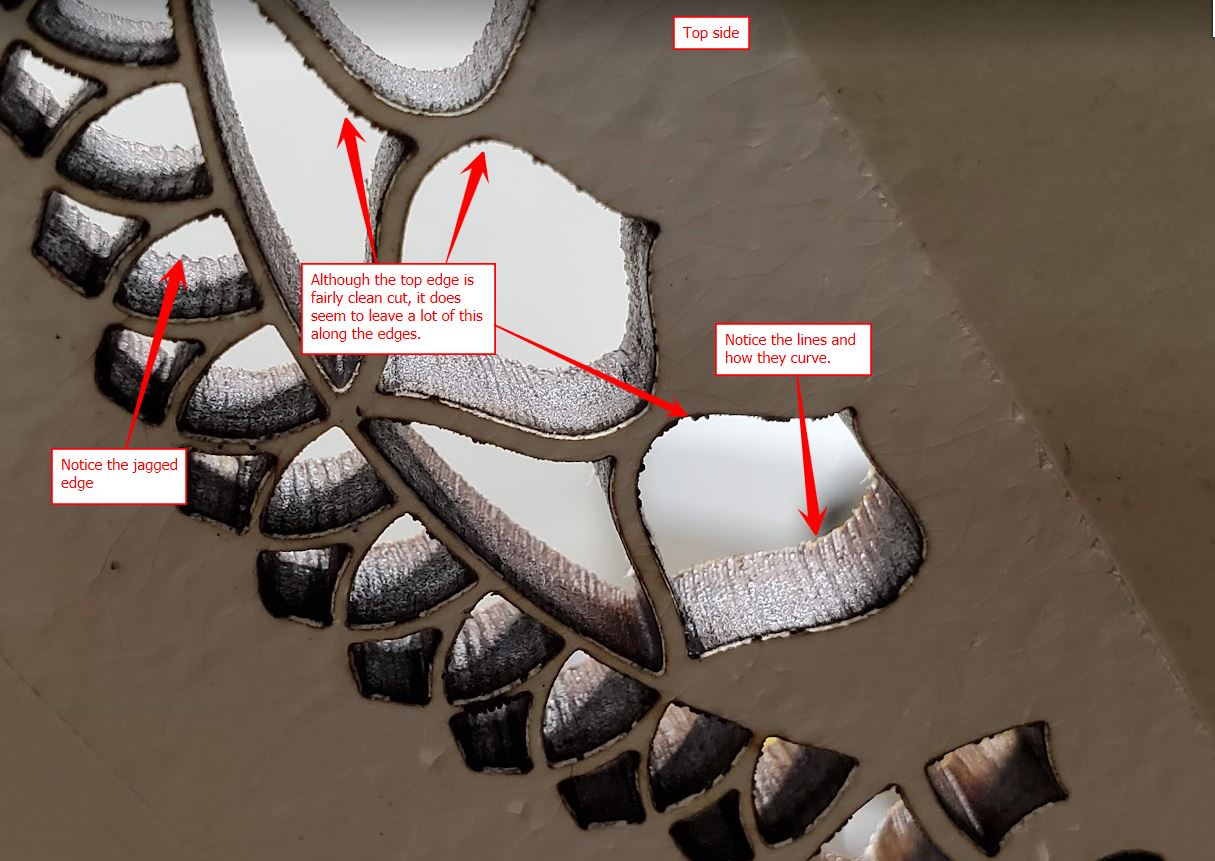
This is from the top side which had transfer tape on it when it was cut. I am thinking that the fuzzy top edges that I pointed out are because of the transfer tape. I just have not tested with out it yet to be sure.
Can someone tell me if those lines are normal? Should there be a jagged edge like that on the bottom side? This was set to constant power but it looks like it is pulsing, hence the dotted lines in the above pic.
Something just doesn’t seem quite right. But I am not well versed yet on lasers. I am hoping someone can help figure this out?
Any assistance is appreciated.
Shawn
The unfortunate problem here is that any mechanical device, in order to move, must have clearance. This clearance that allows it to move, is what creates backlash.
You can diminish it, but if it moves, it will have backlash, that’s physics … The best and really only option we have it the offset scanning adjust. This is also in the controller.
I’ve run quite a while without any backlash correction, but I usually keep it snugged up… it’s still there, just not visible in most operations.
I keep my speeds down… higher speeds exacerbate existing backlash.
![]()
So this is a backlash issue? I have gone through and checked the belts and pulleys and nuts and bolts to make sure everything is tight.
I guess I am wondering if these issues are normal and I am just being overly critical about it? It just does not seem right to me ![]()
Those images were cut at 20 mm/s. I guess I could try slower but that seems fairly slow to me as it is.
This brings up a question that I have been meaning to ask for a while but keep forgetting. Kind of off topic but kinda not. I know there are usually many different speed/power combinations to cut things out on my laser. I can go faster by raising the speed and power or I can go the other direction. My question is, does slower speed/lower power produce a better edge (meaning color/char/residue) than faster speed/more power?
Hi Shawn
Within’ reason slower speed/lower power should produce better results, especially if the issues You’re having are indeed caused by backlash.
One thing is granted though, the curving at the bottom of the cut will be reduced when the speed is decreased, and increased if the speed is increased.
But reduced only if the power is increased at the same time, often leading to unwanted results.
The same curved pattern happens with all the similar cutting methods, oxy-acetylene, plasma, etc, that’s just the nature of the cutting method.
The jagged edge and the curving lines in the pic above look a lot like vibration patterns and those two examples have the same exact intervals.
If the behaviour is caused by backlash, the interval should change when the speed changes.
Obviously, if the dimensions of the shapes is really small, that may be just the normal cutting surface roughness that can be expected with laser cutting.
Regards,
Sam
![]()
Thanks Sam for the info! Very helpful!
Although these examples are very small intricate designs, I see this on larger designs as well. It seems most noticeable on the smaller ones though.
I am kind of on the fence about the backlash theory. I understand how backlash works in situations where there is/has been a change in direction but these holes are very small and there is not much direction changes other than the X and Y moving at the same time. Since I am not well versed on how the steps work with the stepper motors when they are moving at an angle or in an arc together, maybe backlash is present. But the fact that the speed is only 20mm/s and the edges on the top side of the board are all clean and straight makes me curious.
I did do some testing today. I followed Russ’s procedure for checking backlash and adjusting the settings in LB to compensate. After making the adjustments I ran this same test pattern to see if maybe there would be some noticeable changes. I did not see any noticeable changes on the bottom side. But I did notice that the lines on the top side were now kind of wobbly. I was surprised by this.
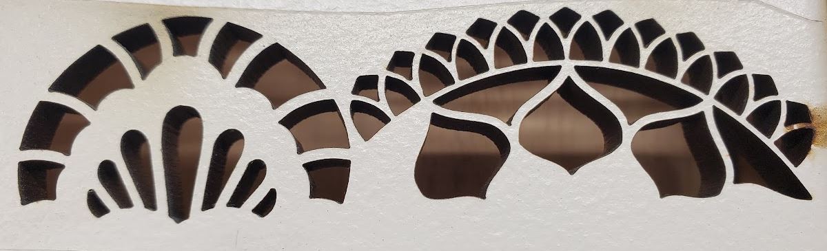
Here is an example of no backlash adjustment
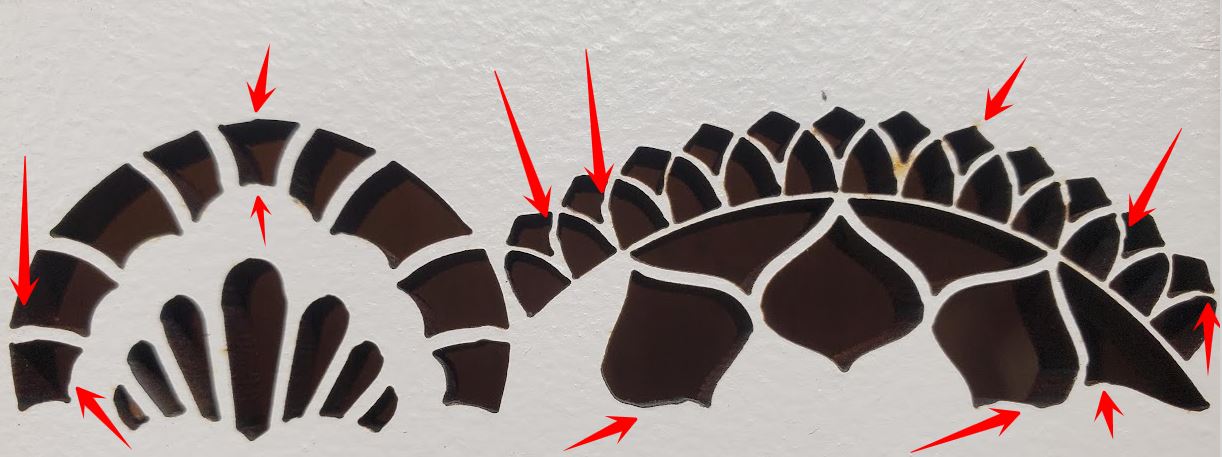
Here is when I adjusted for backlash. Notice that pretty much every line is messed up. I pointed out many of the obvious ones.
What I find odd is I also tested this pattern using an external air supply blowing the surface of the material while cutting to try and minimize the residue buildup on the top side. In my testing I noticed that it too caused the lines to be wobbly. I had one test with low air flow and it was not wobbly but there seems to be a point where too much air caused it to wobble. Not sure I understand why or what is causing this. The air line was right near the laser nozzle pointing directly at the cutting point. Maybe I need to play with the distance, angle, and intensity some.
Anyway, Thanks for the info!
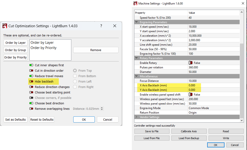
See pic below…what settings did you change for the backlash? There is a ‘Hide Backlash’ optimisation setting in LightBurn’s Optimzation Settings, but the Ruida controller has it’s own backlash setting which is accessible from LB machine settings but is not an LB setting per se, and I would not recommend it for addressing backlash (at least not without more testing, since the last time I tried using it I was not convinced it was helpful);
I have a few questions with regards to the jagged edges: What exactly is that material? how thick? Are you using air assist? What were the ‘Min and Max Power%’ values for the cut? Are you focussed at the surface? What length focus lens?
Hi.
You’re welcome Shawn.
If the pattern always has the same interval, it is naturally more noticeable when the design is small.
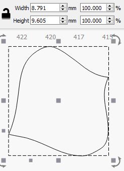
When You say small, actually how small are the three “onions” for example?
@NicholasL raises very good points about the other variables that play a role in this as well, I for one assumed automatically ~6mm MDF/HDF as the material from the pics.
Also, what’s Your spot size/kerf, close to the pattern interval?
Mechanical play/backlash is next to impossible to get rid of completely, and if the carriages are adjusted “too tight”, a whole new set of problems arise.
The backlash plays a role always when there’s movement, it’s just that it is most noticeable when the direction changes rapidly onto the opposite direction.
That depends, there are both the kinds that change X&Y(&Z) at the same time, and the kinds that move X&Y(&Z) in sequence.
I’d be inclined to assume that on most lower budget systems they move in sequence, because the accuracy of that method is more than enough for the majority of the applications.
Not to mention a whole lot cheaper.
The carriages may be too tight, and that may also lead to vibration.
The easiest way to test the effects the mechanical backlash has (regardless of the application), is to loosen the adjustment significantly, test, tighten, test, repeat until there’s no improvement.
Depending on the adjustment method, the other often used method is to tighten the adjustment to a predetermined torque, and the back off a predetermined angle on the adjustment screw, or whatever is used to adjust the play/backlash.
Just like the conical roller bearings for example are adjusted in mechanical engineering applications.
If the “point of no improvement” do not produce the desired results, the culprit most likely lurks somewhere else.
There may be at least two separate factors at play with the air supply causing irregularities.
First, the oxygen-nitrogen ratio of air is such that up to a point the oxygen aids in the burning process, and when that point has been passed, the nitrogen starts to retard the burning process.
Secondly, high velocity, high volume air stream at an angle will at some point start to tilt the laser head if the nozzle is fixed to the head, especially if the fixing point of the nozzle is located farther from the carriage.
Torque = force x distance and all that ![]() .
.
Regards,
Sam
![]()
I use the Hide Backlash setting in LB always. Mainly to eliminate the very slight step in arced shapes where the laser begins and ends. In my work these steps are noticeable so I need to be sure they are not there. This works pretty good at that.
The Ruida settings are what I tried for this test. Now that I think about it, maybe I should have tested the Ruida backlash settings with the Hide Backlash turned off. ![]() Anyway, the Ruida settings did not help.
Anyway, the Ruida settings did not help.
This particular material is 1/4" MDF. I get the same results on different plywoods and hardwoods.
Yes. I have tried with my nozzle at different distances from the material. I have read that by getting the nozzle closer to the material it allows the air assist to actually help the cutting by forcing the air into the cut and clearing the residue. I did this by moving the lens closer/further away from the nozzle inside the tube. I did not see much difference in this test though.
On my 90W I found the following settings worked best where I do not have to work too hard at getting the pieces out. The majority of the time with this 1/4" MDF the pieces seem to stick slightly due to built up resin in the cut. But they come out usually with just a tap.
Bare board/painted
Speed - 20
Min/Max Power - 75/75
Transfer tape/double sides tape
Speed - 20
Min/Max Power - 85/85
I have the Min/Max the same during these tests so I can eliminate any power fluctuation by the controller.
Center of material. I did a ramp test each time I moved the lens inside the tube to make sure I knew where the focal point was.
The seller told me it was a 2" lens but through extensive testing I believe it is a 2-1/2" lens.
I will mention, in case you may not have read further above, originally I was seeing this in 1/8" hardwood/plywood. After a ton of testing we found that using the Kerf setting in LB was causing it. I found that I could repeat the problem. But once I zeroed the kerf out the jagged edges pretty much went away. My Kerf is set to 0 now though.
This is my kerf sizes when tested a few months back.
X axis = .005"
Y axis = .004"
When you say “carriages” are you meaning the linear bearing (Hiwin) to the rail?
Since I am not sure exactly what part is the carriage, can you explain how to make these adjustments? If it is belt tension, then I have done this numerous times. I think they are adjusted pretty good. But I have read that some people/machines like the belts looser and some like them tighter.
As I was lying in bed last night I was thinking about this and I pretty much came to the same conclusions. I think that the direct air may be causing the top edge to burn slightly more before going out. And yes the air line is zip tied for now to the air assist inlet which is connected to the nozzle, so the force of the air coming out could definitely add a slight amount of head movement. The permanent mounting location will not be attached to the head at all. So hopefully that will help if this is part of the problem. Also I will have the ability to maneuver the air nozzle around and also have a more diffuse nozzle so it is not so intense/focused. More testing when I get all the pieces in place.
Thanks for the other info. It makes sense.
Is this an RF machines kerf measurement? .004" is 0.102mm. I looked at one of my 5mm sub flooring cut with 2" and my kerf appears to be ~0.250mm - almost 2 and a half times larger than yours? Mine is set for ~0.125 for each side.
A normal 2" lens produces a spot of ~0.205mm, so a kerf size of anything < 0.205mm, in this case, is rather unrealistic.
![]()
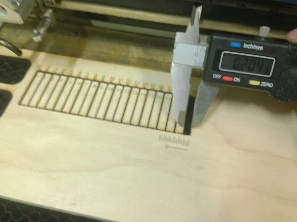
I tested it the rudimentary way like this.
Thinking I should run it again. Maybe I misread my calipers. I do know that when I set my kerf to .0025 in LB my pieces/holes were fairly accurate.
Is there a better/easier/more accurate way of figuring out kerf size?
That looks like it reads 0.204 but I can’t tell the units…
There is a nicer tool that @BillieRuben built … it has a vernier caliper built in… You should get the same results either way.
![]()
Sorry. That image was from a site that explained how to perform the test. It is not a picture of my test. ![]()
I will look into that tool. Either way I will try and run a new kerf test in the next day or so. Although I think the results would only play a very small part in my current problem.
Thanks for the link.
Probably, but we can see that’s likely an issue here or down the road… Just though I’d say something.
![]()