Possibility of scanning rounded shapes in a rectangular scanning pattern

Hello everyone!

I’ve passed the last few days trying to troubleshoot my DIY CNC-laser machine.

The problem was that my machine would engrave some text in a slanted way.

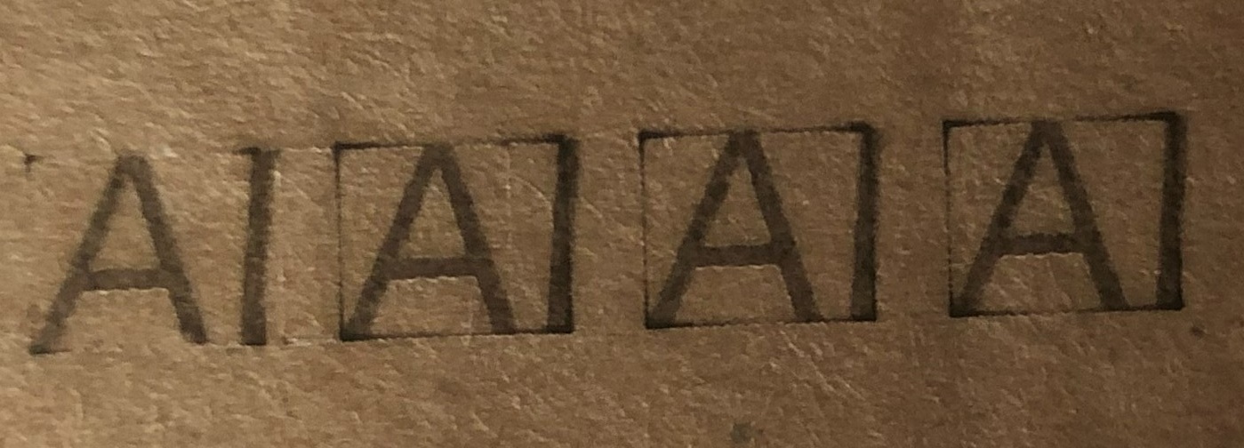
I tracked the problem back to only the text starting with letters having their left side rounded or slanted (Like “A” or “S” or “O”) that led to slanted scanning patterns, see the figure for an example:

As a counterexample, the text starting with letters with a perfectly perpendicular (w.r.t. the scanning pattern) left side (Like “M”, “R”, “P”) led to squared scanning patterns, and those didn’t come out slanted. See the figure for an example:

I noticed the problem got even more accentuated with higher DPIs settings, which led me to believe it had something to do with accumulated systemic error in the movement of the X axis between line intervals.

So i thought, if it were a mechanical issue causing that, then the error would be building up even with the squared scanning patterns, but it didn’t: those engravings didn’t come out slanted.

I was still skeptical, so i tested my machine with a comparator (0.01mm accuracy): running a repeatability test showed no significant build up of error, not even at high speeds. But that was only for the kind of substantial and squared movement like X+10, X-10, X+10… or, back and forth by the same amount.

I tried slowing down my machine (feedrates and accelerations), double checking the step pulse polarity (it was correct) and even trying all combinations of it for my X and Y axes… the problem still remained even with turtle velocity engravings! (The slant angle didn’t even change at high feedrates and accelerations!)

So i went back to software-level troubleshooting… I noticed that the GCODE of the “squared scanning patterns” was of the type of “substantial and squared” movement i worked with in my repeatability test, but that of the slanted scanning patterns was not.

It had a peculiarity: I noticed lots of lines in which the Y-axis movements (those which serve to go up by 1 line interval in the process of engraving) were coupled with X-axis micromovements of the size unfortunately smaller than the precision of my machinery.
You can see one right after the overscanning G-Code in the following figure (the line is below the gcode of the 2.5mm overscanning):

These type of lines, which i believe are the reason for the “rounded” sides of scanning patterns, were not contained in the GCODE of the “squared scanning patterns” (or, at least, they are there but in minimal part, just for the rounded tips of letters! I believe there is some error there too, but it’s invisible to the human eye cause they are not that high to notice).

So, the problem can now be of one of two kinds: it can be a electromechanical problem (like, my PSU can’t drive two stepper motors at the same time, which i find it hard to believe granted i’m using a modified 3000W one… maybe the transient is too big even with such a small step?) or it can be tracked to a precision problem of my machine (but being a humble DIY machine i can’t really ask that much precision).

I do believe i can still engrave with high DPI settings if I manage to make the scanning patterns rectangular!

With this post, i wanted to ask you if there is a setting in lightburn to make it possible.

I think i’ve found a workaround, i’ll try it tomorrow: i use powerscaling to “hide” a straightening “ghost” 0.01mm thick line on both sides of the text, with power set to 0%, so it doesn’t get engraved but still gets scanned.

The question still remains if it is possible to do such a thing without this workaround…

The GRBL G-Code interpreter does not discard “small” command distances, but adds them to the current position, then issues as many motor steps as required to reach the new position. A commanded distance can be so small that no steps happen, but the accumulated position will remain accurate to within a single (micro)step.

So that’s not the problem you’re seeing.

If the STEP pulse going to the motor driver has the wrong polarity, it will cause a loss of position depending on the exact motion pattern. This is most common in machines with misconfigured (from the factory!) Ruida controllers, but it can happen to any machine.

The doc explains it for Ruida controllers:

Pay particular attention to the “What is this setting and why does it matter?” section, then verify that your configuration has the correct STEP polarity. Typical stepper drivers require a negative-active STEP pulse, so be certain the GRBL controller configuration produces negative-active STEP outputs.

If verifying that doesn’t improve the situation, upload the offending lbrn2 file, the GRBL configuration settings, and clear photos of the results on the material (use cardboard until it’s working). That will give us more to consider.

Sorry for the late reply, I had to do some maintenance on the machine.

My machine is based on G210X stepper drivers, with common connected to GND. Looking at their manual it tells me microstepping occurs on the rising edge (i assume it’s the negative-active transition you are talking about) of step pulses.

I’ve set up the GRBL controller accordingly to the manual, so I simply did not turn on the “invert step polarity” for all my axes.

Since I’m still skeptical about how the controller sends pulses (i don’t have an oscilloscope unfortunately), I’ve made some tests on cardboard as you suggested (plus, i’ve marked the frame by putting the framing laser output to 20%):


First one on the left is step polarity invertion disabled for both X and Y axes, second one is step polarity inverted just for the X axis, third one is step polarity inverted for both X and Y axes, fourth one is step polarity inverted for only Y axis.
The engraving starts from the bottom of the text and works its way up… As you can see, all of them are tilted to the right.

For all tests I’ve used the same configuration you see here, except I cycled the step polarity of the X and Y axes to try all combinations:


This is the offending file:
TEST CARDBOARD.lbrn2 (9,4 KB)

I did try the workaround i’ve described earlier too, and it seems to work!

If i have to make a guess, the problem originates from the fact that my machine never reaches the max speed i’ve set up in the cut/layers tab.

I think the different lengths of scanning lines translate to different peak speeds of my stepper motors. Since torque goes down with speed in stepper motors, i think there is some interplay between the torque, friction and inertia of my machine. With same lengths paths and left-right-left-… scanning patterns, I think the lost steps are minimized since the forces balance equally in the going and return passes, but this doesn’t happen with the slanted scanning patterns.

Ah!

I think this part of the doc is relevant:

This means morphing from a microstepping to full-stepping when the motor speed is above where microstepping is of any benefit (above 4 revs / sec.)

Because it’s changing the motor step interval on the fly as the speed changes, then their definition of “accuracy” probably applies to the endpoint of the motion, not to the trajectory in between, which would explain why it produces odd results when the motion should be running at a constant speed.

We’ve seen a number of cases where “smart” / servo / closed-loop motor drives produce poor results, because they’re optimized for something other than laser control that requires precise speed control.

Here’s one horror story:

This seems like a similar situation.

1 Like

Unfortunately I can’t turn off that functionality, it’s built in…

I tried to override the step morphing by setting the pulse multiplier of the X axis (only) to full step instead of the base 10 microstep resolution, but the text remained slanted.

During the testing i noticed something though:

The X axis motor was now running at full step and I could hear loud thuds coming from it during the direction changes. I figured it must be because with full steps I have to ease the acceleration, but then something strange happened…

The Y axis was losing a lot more steps and even totally stalling during the X axis’ direction changes, with its same acceleration settings that never gave me any problems!

Since the Y axis moves at the same time of the X axis (see the Gcodes I’ve screenshotted in the first message of this thread), is it possible that the full steps of the X axis required a higher transient of power and that made the Y axis stall? Or is it possible I’m experiencing some kind of energy return from the X axis deceleration that makes my Y step driver behave incorrectly?

I have no capacitors installed on the drivers’ DC supply, mainly because there is nothing written about their installation in the G210X manual, but I could see that some sites report it was a practice commonly seen with older Gecko equipment… could this be a solution?

Could it be that instead it’s simply the PSU type to not be correct for my application, and I should use separate PSUs for each axis? Since the GCODE makes the X and Y axis move at the same time in a diagonal movement, i’ve got this hunch that it may be that my PSU, originally made for the typical steady amperage requirement of servers, can’t keep up with the transients of stepper motors.

The G210X may be the wrong type of stepper motor driver for this application.

The controller regulates the speed and acceleration of both axes as needed to meet the commanded speed. When you changed from microstepping to full stepping, then (presumably) you also changed the step/mm (or mm/step) value for that axis, which will affect how the controller accelerates the axis. That change will also affect how the other axis moves, because both axes must cover the proper distances at the same time.

Because the stepper driver seems to changing the motor step ratio of at least one axis while it’s moving, that’s likely the problem.

Stepper motors are essentially constant-power / constant-current devices, so they do not have surges or transients similar to those with old-style DC motors.

If the supply has a maximum current rating close to the combined maximum currents of everything it’s powering, then there can be problems:

  • What power supply does the machine have?
  • What are the stepper driver current settings?
  • What (else) is connected to it?

However, I think the G210X is the real problem.

It’s a CISCO’s WS-CAC-3000W, i’m operating it at 240V so i got 66A on the 42V DC line.
I’ve set all drivers to supply 4.0A to my Nema 23 motors.
I’ve got just another cable attached to the 12V line that supplies current to my GRBL HAL controller.

I can’t find any detailed specs, but it’s surely overqualified for the job at hand. :grin:

Which leaves the G210X drivers …