I had just finished installing a milliamp meter on my new OMTECH ZF2028-60E 60-watt laser (it has a KT332N controller). Too make sure I had the wires connected correctly (the instructions I found online were wrong) I put a scrap piece of 1/2" plywood on top of my pristine waste board (I hadn’t engraved the 700 by 500 grid yet) and hit pulse twice. Once would have been enough but I couldn’t believe I hooked up the meter incorrectly. When I picked up the plywood there was a hole in my waste board and one all the way through the plywood. That got me thinking: how much power (what percentage of total output) gets emitted when you press the pulse button? Anybody know? I did have a look around but couldn’t find anything.
It’s set on the machine console, along with the manual speed.
On my KT332N, Enter puts the edit cursor on the Speed field. Down arrow to the Power field, Enter to edit it, another Enter to edit the Max power field, then you’re in the UI hellscape of numeric entry.
When you’re done with that, set the pulse duration to about 30 ms through the Menu → Laser dialog.
A 30 ms pulse at 30% power lightly toasts posterboard during mirror alignment and pokes pinholes in chipboard when aligning the red-dot laser on the platform.
On my 6442g I have to enter the area with the Z/U key, then select manual laser to set either continuous or pulse duration.
I have to back out to the console and press Max to set the percentage power…
![]()
It’s almost as if they never expected anybody to use those functions …
I may have to look at replacing the membrane on the keypad… it’s starting to open around the most used buttons.
I think I saw a clear replacment for it somewhere…
![]()
The first part worked exactly as you described, I was able to slow console framing speed down and I arbitrary set the power to 13% (it was 20). I’m sure I will turn it back up as I get a chance to play with it.
The second part was a little different. From the console I selected Menu…Laser Set…and found the default was Continue (Continuous I assume) at 0 ms. I changed it to Laser at 30 ms as you suggested. I think the fact that it was set to continuous was the majority of my problem, as I now get a nice short pulse.
The thing that’s concerning me now is that the nozzle/lens tube tends to wobble a little where it enters the head (just below the 3rd mirror. There’s a knurled knob holding the tube in place and that’s the pivot point. It implies that there is not much tube above the set screw. I only have about 5mm between the nozzle and the workpiece (my 50w had 19mm). It’s as if the tube is sticking out too far. I’m going to have to do some investigating. Anyway, thanks for your help.
If the lens is in the tube, slid it further in head assembly and raise the table to make up the difference.
This is confusing… are we dealing with multiple machines?
![]()
Sorry 'bout that. Works the same way here.
Yeah, that whole thing can fall out in the middle of a job:
The flange on the lens tube should sit against the bottom of the upper tube, whereupon the ring should tighten the collet around it. The label reminds me which way it should turn.
With the standard 2 inch lens, the focus point is 18.5 mm below the nozzle, well below the autofocus “pen” switch:
It seems like your machine has the lens tube just barely inside in the collet, with the flange not doing anything useful.
Perhaps one of the collet fingers is missing or there’s something jammed in the collet slots preventing it from tightening?
My apologies for the confusion Jack. For the last year and a half I’ve been running an OMTECH MF1220-50. The focus tool on the 50w was about 18mm thick. A few weeks ago I bought a ZF2028-60E (and sold the 50w), so I’m getting used to the differences between the two machines. The nozzle/lens tube on the 50w was rock solid. Not so much on the 60w. As I mentioned, there’s a big difference between them in the distance from the nozzle to the workpiece. The focus tool that OMTECH provided for the 60w is 5 to 6mm thick, and I get a nice focused dot when I pulse the beam. I’m just not happy with the amount of play in the tube.
This is why many people change out that head assembly to something more functional…
The hole on the side of my factory head wasn’t even in the center of the lens/tube path… not to mention it was pretty heavy.
I went with the head design of Russ Sadler with the C series lens tubes.
The focus distance is how far the material is from the lens… For a 2" lens… so the nozzle matters…
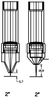
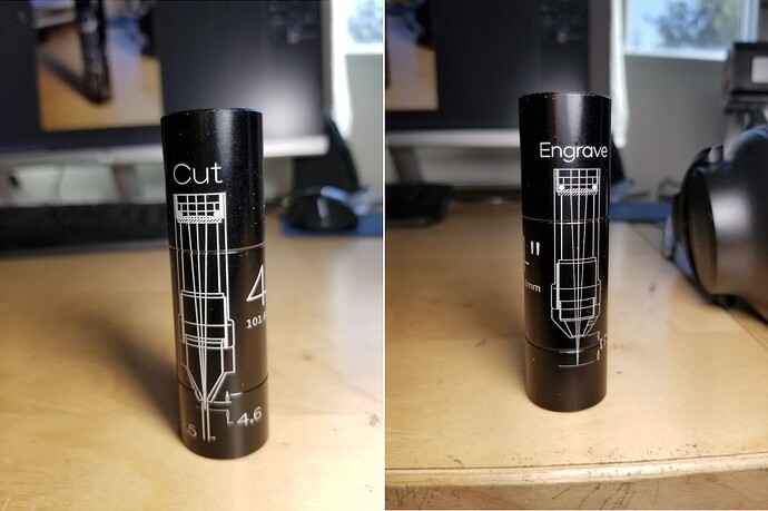
Need to take a photo of the engraving on the tube… I do have one for the 4"… I engrave what lens/focus distance… Don’t remember ![]()
Good luck
![]()
Thank you for the information Jack. I don’t know how much of a problem this is going to be down the road, whether I should look into getting a lens/tube assy., or if I should contact OMTECH about it. In a nutshell the lens tube is slightly too small and it rocks back and forth ever so slightly when touched. Please excuse the poor drawing but it might explain it better.
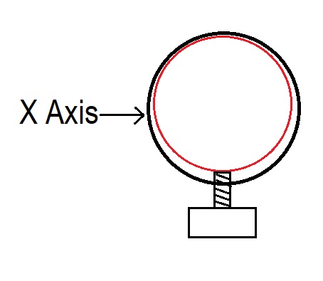
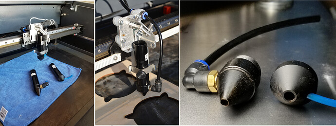
The red circle is the lens tube and it pivots at the set screw, along the X axis, enough for it to bug me but I don’t know if it’s enough to be detrimental when cutting or engraving. After resting the nozzle on a 3-2-1 block to set nozzle height I removed the lens tube from the head. There was about 15mm of tube above the screw mark. I pushed it in another 15mm or so but it had no real effect on the wobble. I suppose I could put a layer or two of Teflon tape around it to take out some of the play. Or I could be overthinking this and I should just let it be. It just bugs me. Here is a picture of the tube and nozzle.
If I was going to replace it, what should I be looking for? I do about 60/40 engraving to cutting.
What lens holder/head you purchase is up to you… There are plenty out there. I like the simplicity of the Russ Sadler designed head myself. Not to mention I’ve removed about 2/3 of the X axes mass. My acceleration value is around 45000mm/s^2.
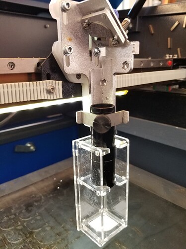
As you can see it holds the tube square to the head. This is for vertical alignment… A 3mm acrylic attachment that works very well… another part from Sadler.
If you wish to pursue one of his designs, let me know…
Good luck
![]()
Which will certainly affect the spot position on the platform, so it’s best fixed.
Rather than squishy tape, use brass shimstock to get a rigid assembly.
Measure the allegedly matching ID and OD, divide the difference by two, then cut a rectangle 30 mm tall by (3 × the OD) from that thickness of shimstock.
Roll the rectangle around the bottom tube (with the gap away from the screw), assemble, and screw it tight.
The lens tube in my laser wasn’t as loose as yours, but the clamp holding the focus “pen” was sloppier, so it now has a similar brass shim. You can see one edge below the red pen clamp:
For sure, they made all the tubes the same OD, so whatever they send will be exactly the same.
Great idea Ed, thank you. Now to hunt down some brass shim stock. Maybe Amazon. I also see you made a collar for your led pointer. I did the same thing for my 50w and now I’ll have to print one for the 60w.
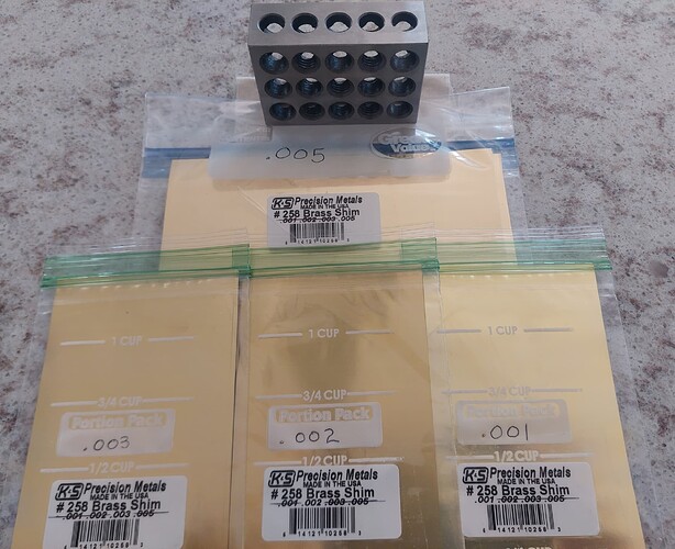
Anybody with a 123 block is required to have a shimstock assortment on the shelf! ![]()
I’ve been whittling away at a big K&S pack for decades and it’s nowhere near gone …
It puts the pointer just slightly off-axis so you can fine-tune the position by rotating the collar. The whole affair is too sloppy for words, but it was a nice thought.
“Anybody with a 123 block”
You’re absolutely right (hangs head in shame as he shuffles off to find some shim stock).
2 posts were split to a new topic: The dark arts of swapping lenses
Looks like a lifetime supply to me! ![]()
Ed, I went to the link you provided in the hope that there might be a link to the STL file you used. Is it available somewhere or is it a product of your fevered imagination? If it’s the latter is there a chance that you might share it? It would be something I’d like to Tinker(CAD) with. If you’re amenable to the idea.


