I originally posted this as a PM to Jack, he, correctly, suggested I include it as part of this thread so that others may benefit from the answers.
“many people change out that head assembly”.
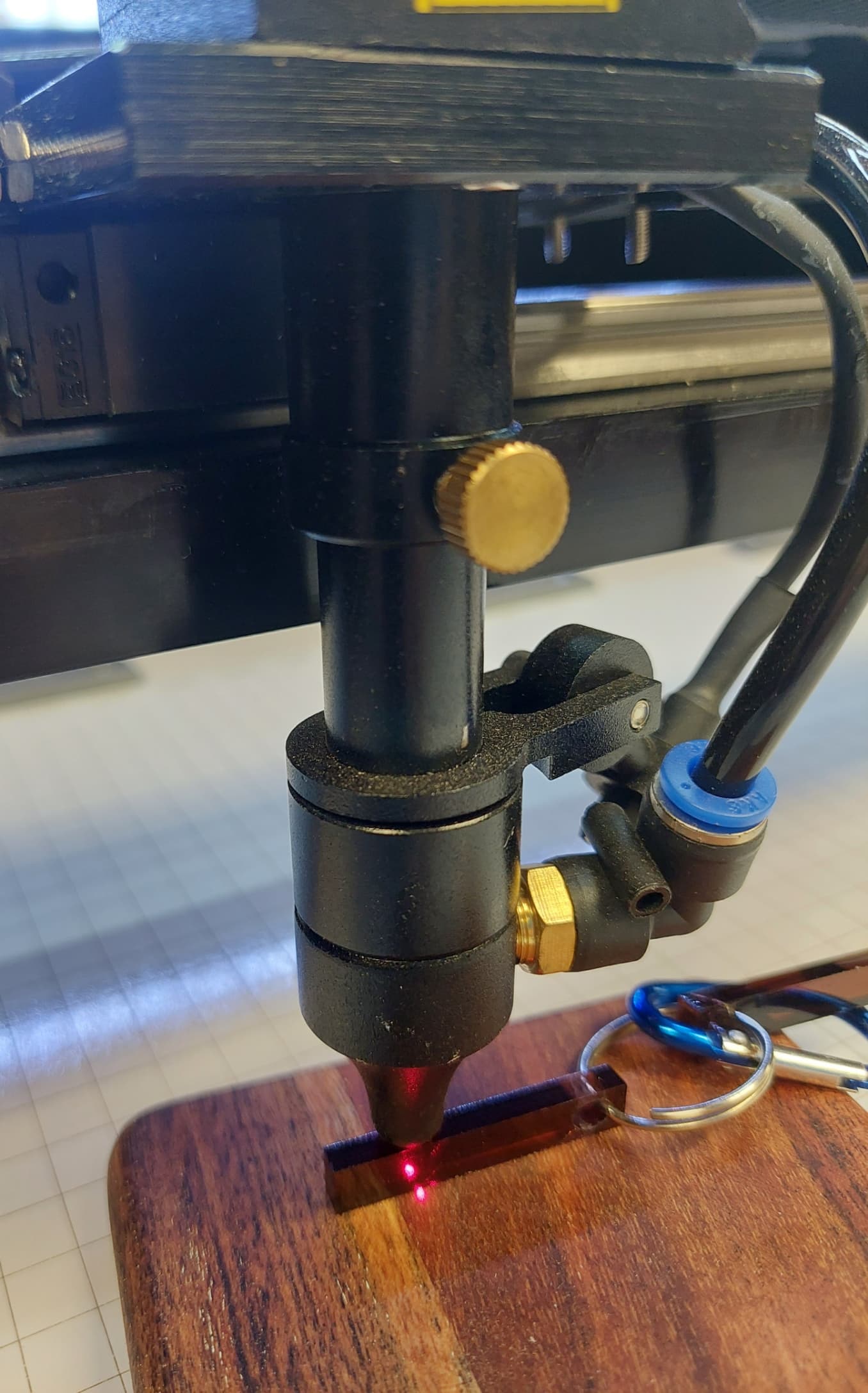
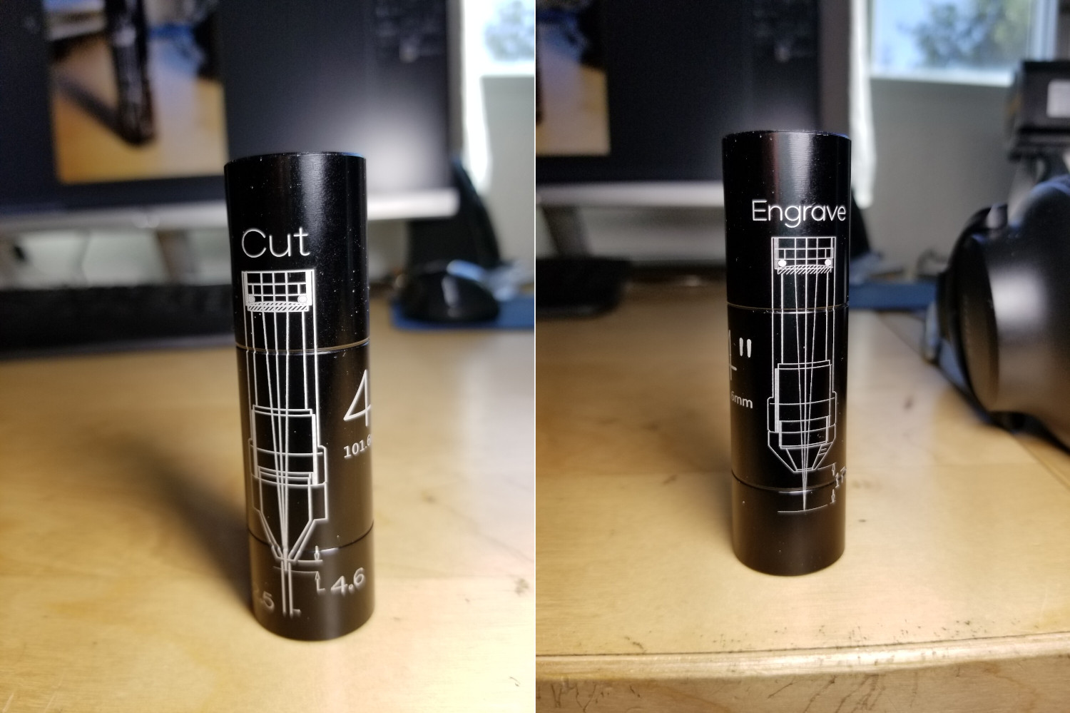
As I plan on keeping this 60w for a while, I will eventually go down that path, just not at the moment. What I would like to do is, if possible, increase the distance between the workpiece and the nozzle tip for certain engraving operations (I have some wooden trays with up to a 2.25" deep rim). The deeper one fits but just barely. I don’t know enough about the dark arts of swapping lenses but is it possible to keep the lens tube/nozzle assembly that I have and replace the lens with one that produces a focused beam that is farther than the ~5mm that I have now? My old (now sold) 50w had a similar tube and nozzle but came into focus ~18mm from the workpiece. I just don’t have a clue what it is I should be looking for, i.e., I don’t know what questions to ask to get the answers I seek. Perhaps someone may be able to provide some guidance.
Common lenses in 18 mm diameter lenses for my laser (and likely yours) have focal lengths from 1.5 inches through 4 inches and cost $20 to $40.
Longer focal lengths focus farther from the lens, so replacing a 2 inch with a 4 inch lens provides an additional 2 inches of room. However, the beam will be wider inside the nozzle and can hit the rim if it isn’t centered. There are other side effects, but mostly you gotta try it to see if you like it.
Although the topic kinda fits here, start up another thread about lenses in particular before we get into an extended discussion.
Thank you John, I was just getting ready to start a new thread as Ed and Jack have suggested. Your title is much better than the one I would have come up with. From what little I’ve been able to figure out, my new 60w ZF2028-60E has an 18mm lens with a 1.5" focal distance. My previous laser (an MF1220-50) had a 2" so I had gotten used to the extra room underneath the nozzle (so as not to bump into things). The new machine apparently has, as stated, a 1.5" which is probably great for cutting but I seem to do more engraving than cutting. I’m looking for input from the LightBurn community for additional lenses I might want to add to my arsenal so that I can tailor my configuration to the job at hand. At a minimum I should get a 2" lens, but beyond that I’m not sure.
I grabbed a selection of lenses for my 100 watt Co2. 4" down to 1.5" My laser is of my own design and I really wasn’t sure of the best focal length. I have settled on a couple that work well for me. 2.5" gets my laser head up away from the materials allowing for some clearance. 1.5" seems to be versatile too. Little more airflow down into my cuts but brings the cutting head very close. I use the 2" as a good compromise for cutting and engraving… It gives me a bit better clearance and works well for most things.
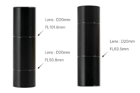
I ordered a 2" from Amazon which should get here today. The seller also has 2.5", 3" and 4" lens as well. I’ll take a wait and see approach and see how things go. I will probably add a 2.5" and 3" to the collection as well (they’re not very expensive) and see that kind of results I get. I’ve seen lens set where there are two lenses and I’m curious as to what kind of situation they would be best suited for?
I use the 4" for cutting thicker materials. I set the focus to 1/2 the thickness. The focus range can be easily seen with a ramp test… Although I’ve cut 6mm acrylic pretty easily with the 2", the 4" leaves a better edge…
If you use any of the standard C series type lens tubes, the published focus value are good. If you do the ramp, it’s easier to visualize the depth of field… at least for me.
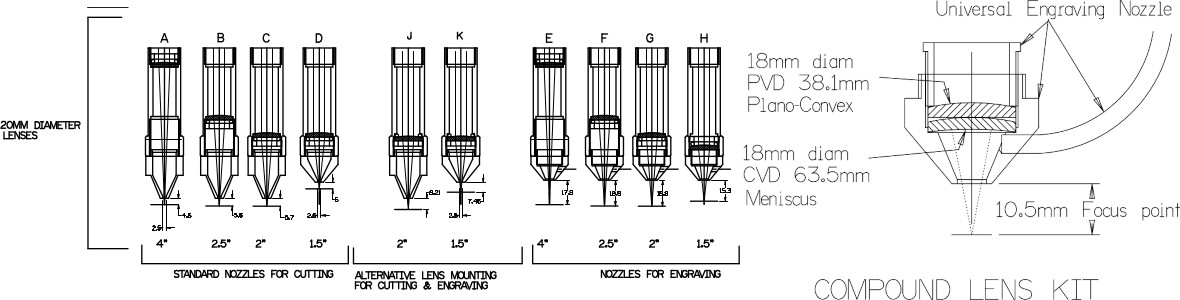
For serious detail, you need the compound lens… I get ~0.05mm … 508 dpi possibility with this lens… It’s focus is critical…
Thanks Jack, this is very useful information. I’ve been using the same power and speed settings on the new 60w that I used on my 50w, cutting the exact same acrylic, and in some places it’s not making it all the way through, even on smaller pieces. I’ve slowed it down a little, and it’s helping, but the parts aren’t dropping out like they used to. It looks like I might (eventually) want to get an assortment of lenses and experiment a little. I’ve been looking for the multi-segment tube you showed, for 18mm lenses, but haven’t found a source yet.
The 60w was delivered a couple weeks ago and was immediately pressed into service. To be honest, I never checked the alignment on the 50w because it just worked, right out of the box. I did check to make sure the beam was in the center of the nozzle. The 60w was more or less the same. Pinpoint beam in the center. I just installed the milliamp meter (had to wait out the 30 day return period) and the current looks similar to what I was seeing on the 50w. My engravings look identical, maybe even better with the new laser. One thing it might be is the acrylic I’ve been cutting is from a new batch of scrap my buddy gave me. He owns a sign shop and gives me all the scrap I want. This stuff has a different covering on it so the acrylic itself might have different properties. After checking my alignment I’ll see if I can find some of the older stuff. The 2" FL lens showed up today, after I get everything squared away I’ll give the new lens a try.
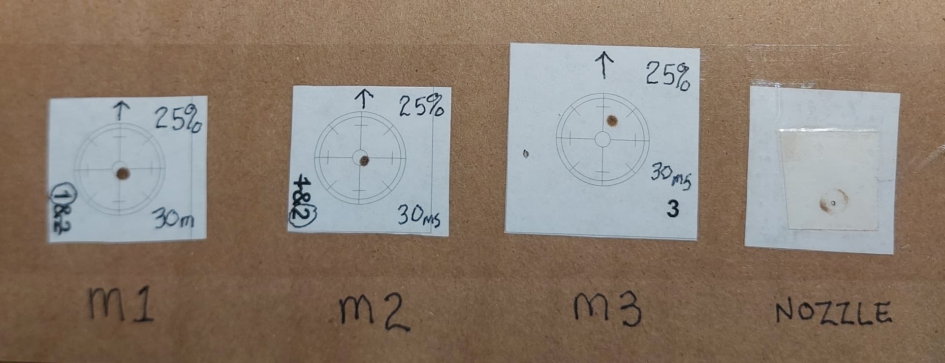
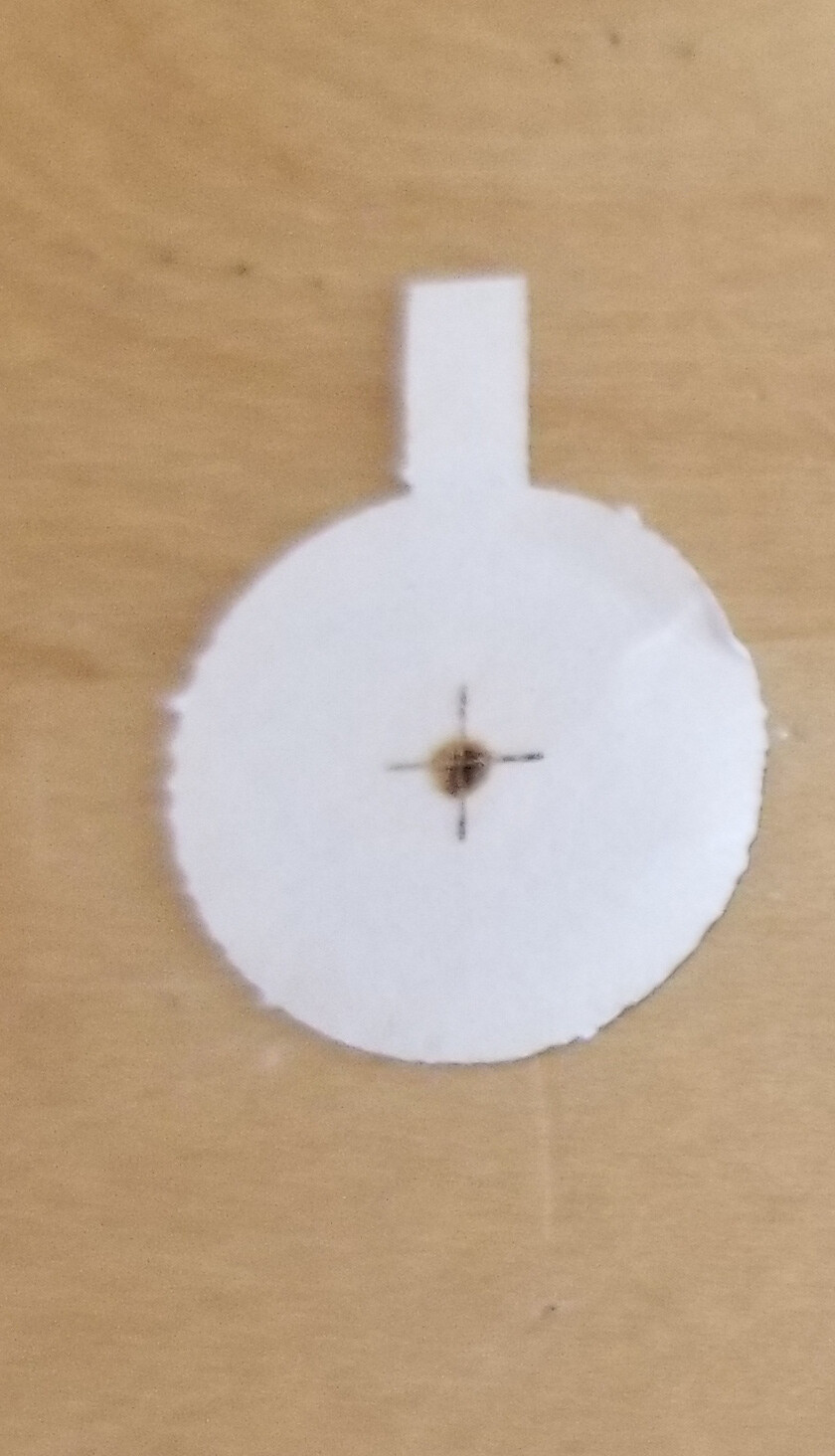
I 3D printed some beam alignment target holders and did a quick check of the beam alignment. I put the head in the middle of work area, and this is what I got (the arrow shows the orientation of the target).
I had the power set to 25% with a pulse duration of 30ms. At a minimum, it looks like I need to tweak mirror 3. Tomorrow I’m going to print up some more targets and move the head around the work bed and see what kind of variations I get in alignment. Unfortunately, I do not have a Mahoney watt meter, or a doohickey for that matter. I’ll have to check the “rainforest place” (that’s how google translator put it when it was changing Amazon from French to English) and see what they have in the way of doohickeys. All the mirrors are clean (I haven’t really had it long enough for them to get dirty).
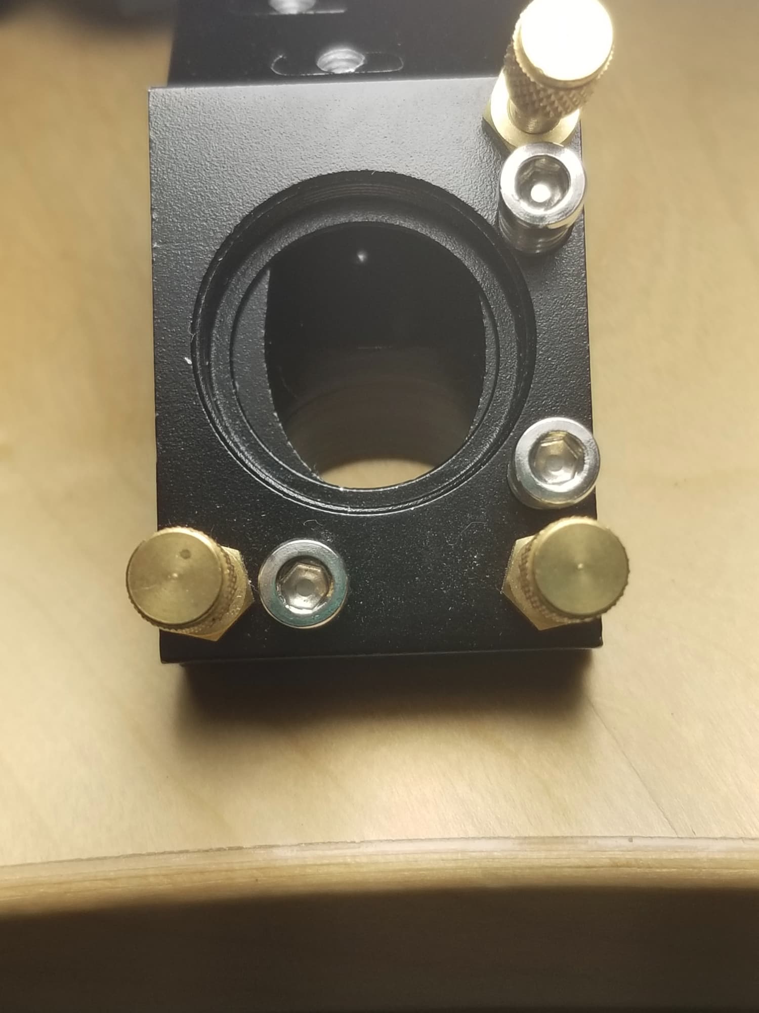
When you check m3 ensure it’s centered… mine was offset to give some clearance to the spring hardware. Make sure you’re targeting the center of the mirror, not the hole…
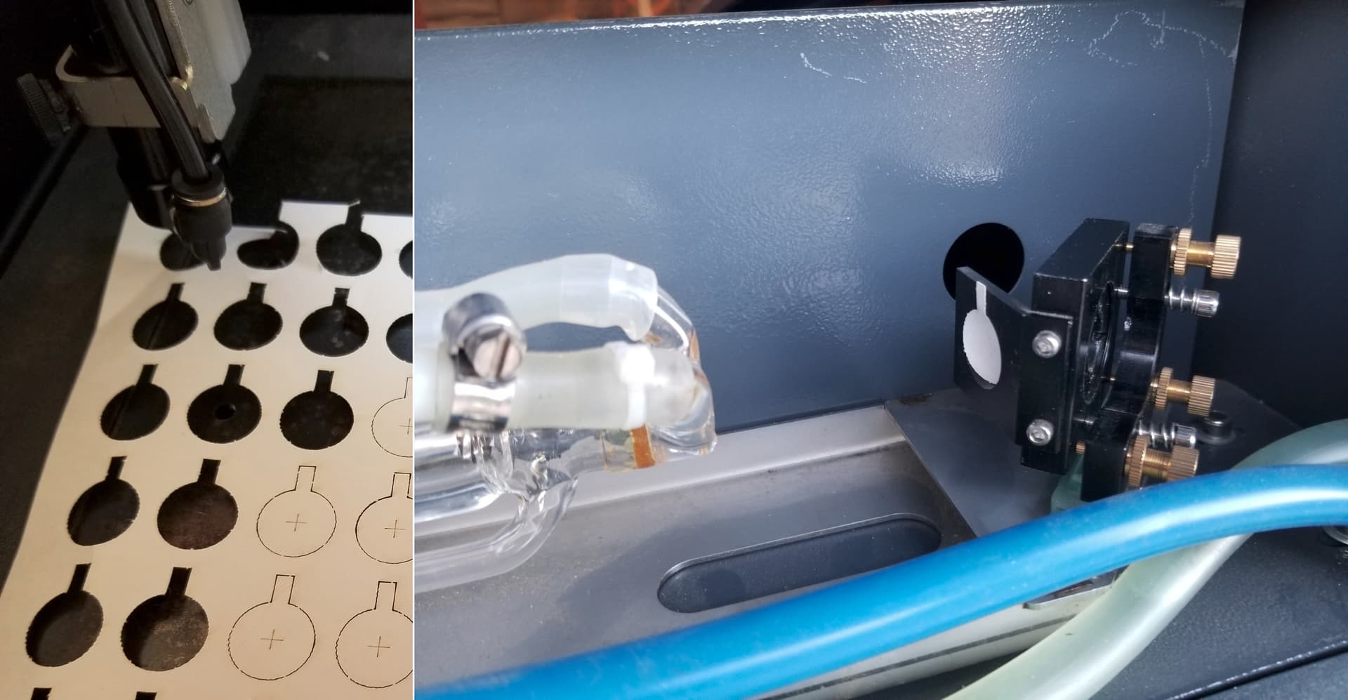
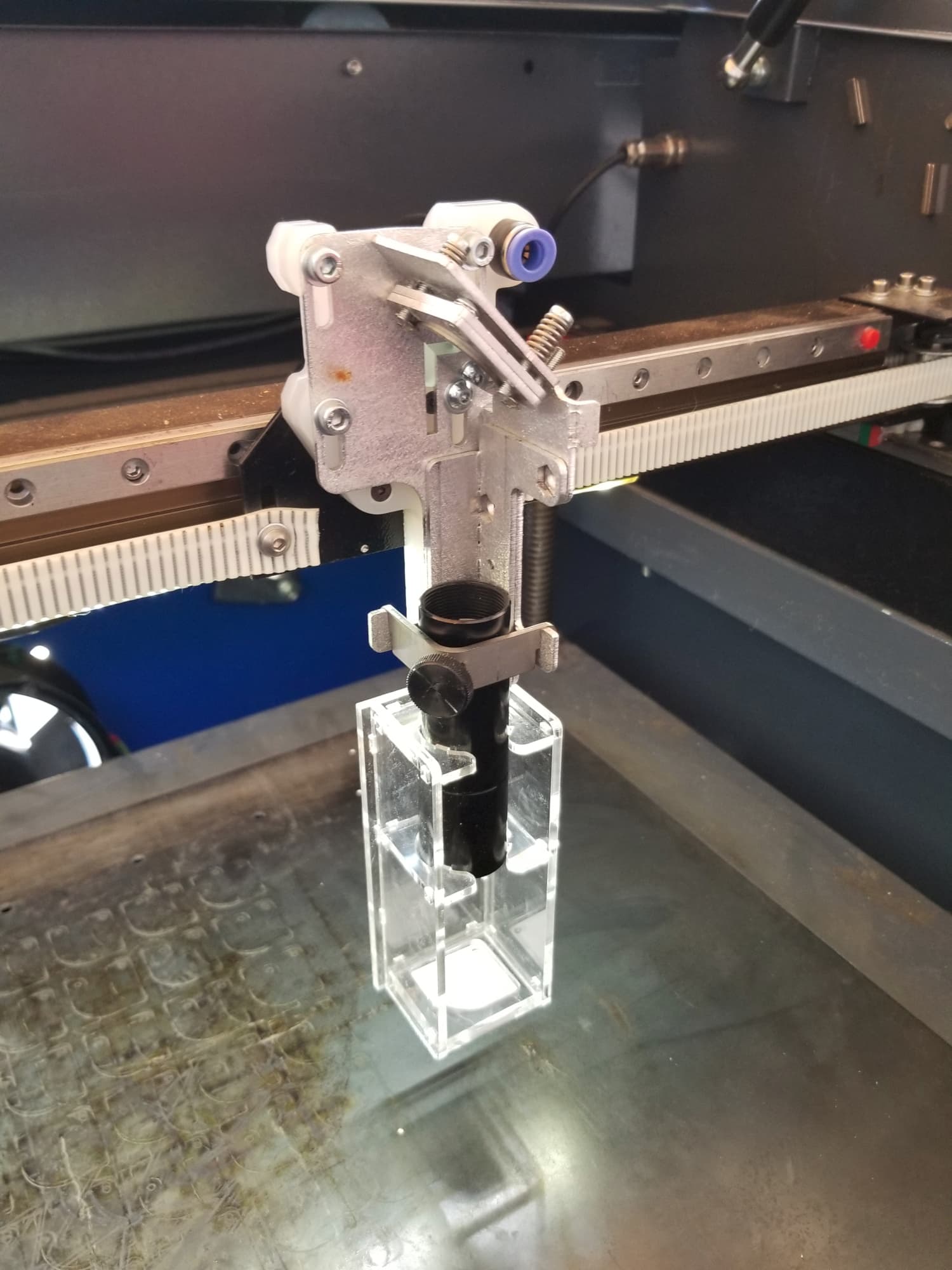
The head I have is pretty open and easy to get into for vertical alignment. I have a target cut that sticks to the spring screws on the mirror. Along with one that fits into the top of the lens tube, beam entry and one at the bottom of the acrylic jig (visible) which is square with the lens tube.
Right after I read your post I realized that I was focusing on the wrong mirror, it’s M2 I need to be tweaking not M3.
As far as you can tell, does the mark on M1 look like it should?
What I want to avoid is taking a working laser and get it out of sorts by me not doing this alignment correctly, as it will be the first time I’ve attempted to do one. I’ll do my homework first and see if Russ has a video to watch (I’m sure he does). All your recommendations have been duly noted.
If that’s what you find, a good alignment may be impossible; it was for me, anyhow.
You have a powerful motivation to get it right, which is more than can be said about whoever did the factory alignment. You’ll get it wrong a few times, but that’s part of learning how to do it right.
Protip: Do not assume anything starts out correctly aligned, including the tube itself.
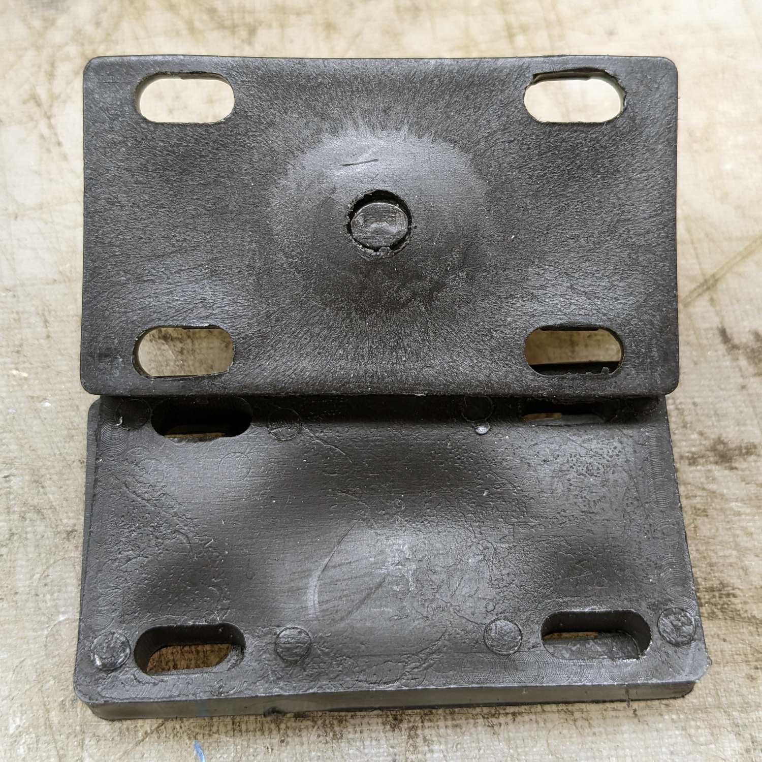
@ednisley wonderful example of their craftsmanship…
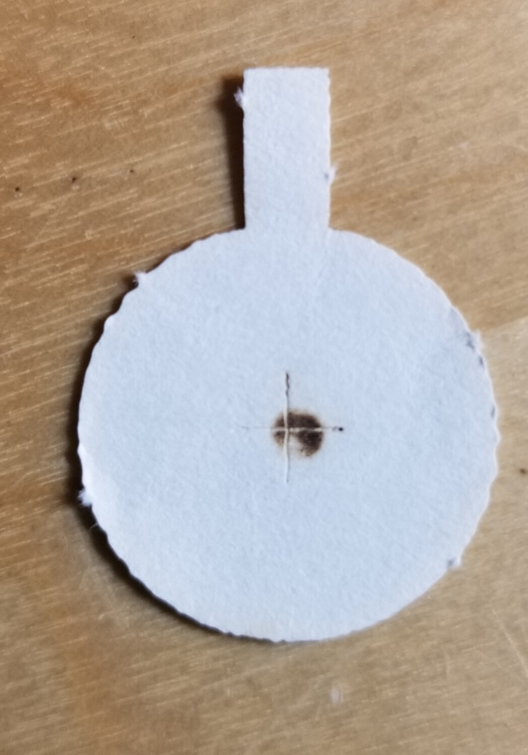
It is too dark for me to really see anything. What you want to see is the power across the beam… it should be dark in the center and go outward getting lighter…
All the rest of the mirrors should have two marks on them. Closest/furthest…
Jack, thank you for the link. I’ve watched it through a couple of times, and I’m with Russ up until 13 minutes in. With the mods he’s installed on his machine, he can do things that I cannot. The situation I currently find myself in is that the beam strikes mirror 1 about the same as your second target picture. With nearly 80% of the beam in the center of my M1 target I’m going to call it good (for now). It is identical for M2, both close and far. At M3 the beam was about 2mm high and right of center (regardless of head position). After making a slight adjustment to bring it to the center, I now have a situation where the beam is centered with the head at mid-point, slightly low & left of that with M2 and M3 close together and slightly high & right with the head to the extreme right. It would seem that the beam is parallel to the X axis rail in the horizontal plane but is no longer parallel in the vertical. I’ve looked for this issue within this forum (and the internet in general) but have not found a solution as of yet. The laser is still functional, but I would like to fix this before I start swapping lenses or making other mods. Any suggestions?
It is a simple approach to lower manufacturing and initial alignment costs by abandonment of these really critical adjustments.
That’s one of the reasons people change that junk out or modify it so alignment is much easier. I changed out my tube, doing the realignment after centering all of the mirrors adjustment threads, takes about 10 to 15 minutes…
Keep the idea of how he does this in mind. If the tube hits m1 off center it will be more difficult to align m2 and m3.
Use one of your targets to measure beam diameter. If it’s 8mm and you use 20mm mirrors the beam sees the mirrors at a 45 deg angle, so it’s actually a target with one of the dimensions at sin(45) * 20mm or 0.707 * 20mm = 14.14mm.
If your beam is 8mm then 14mm - 8mm is 6mm leaving 3mm of mirror on each side of the beam when it strikes the mirror. Not much leeway.
Your beam size and mirror combinations will dictate this. If the beam doesn’t go down the center of the lens tube, it will have an exit angle that is not perpendicular to the table.
With these you do the best you can… I had to shim my m2 at one point, before I replaced that mirror mount that had a Y axes adjustment. I had already tossed the head.
You probably know that strike right of center requires you to move m2 along the Y axes to center the beam along the m3 Z axes. Raising the head along Z axes, will move the impact down towards m3 Y axes…
It makes you very aware of the adjustment shortcomings of these machines.
I’m happy with the head/rack and pinion drive that I got from Russ… The earlier photos are my machine…