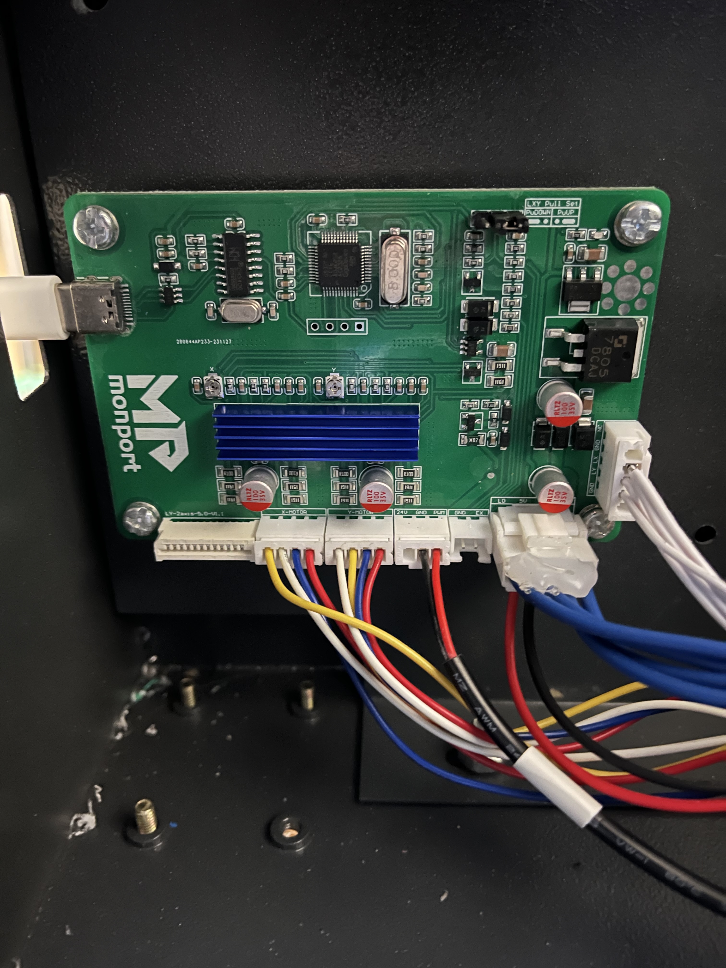
I purchased a used OMTech K40 a couple of months ago and finally decided to set it up in the garage last week. Out of the box it was bot lightburn compatible, so i purchased this controller upgrade from monport. it is a straight plug/play replacement.
Unfortunately, I am unable to figure out why any power adjustments made through lightburn seem to have no affect when running a job and i am currently burning through material. I’ve run tests with small squares and adjusting the power settings in each layer, but there is not distinguishable difference between any of the shapes. is there some setting i have not applied that will fix this?
not sure im understanding the question. it was wired directly to the machine four harnesses replaced the harnesses from the original controller. no need for complicated re-wiring
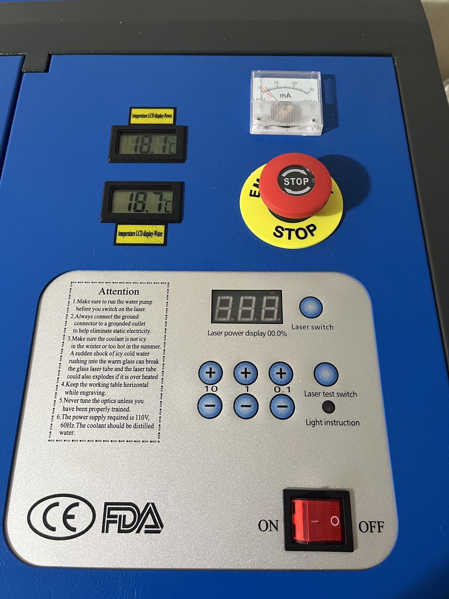
there is a digital display on the top panel with touch buttons that seem to be for adjusting the power; however, i think upgrading from the original controller to the one i linked above renders this non-useable anymore. When installing it i referred to this tutorial for a similar controller upgrade. In the video the person making the upgrade says the panel will no longer be useable and removes it from his machine
You’re assuming that all systems are the same. I’m looking for specifics on exactly how it’s been wired to know what signals are involved and where they’re going on the rest of the machine. What on the controller goes to what elsewhere in the machine?
The controller in the video is different from the one you linked to. Was the connection to the top panel the same as what was on your laser?
Also, I’d like to confirm that you’re in fact not getting power modulation.
What settings have you actually tried? Have you run a material test?
The controller in the video is different, but the connections are the same. Power, limit switch, x and y axis (I think it is the other upgrade controller shown on the monoort website). The biggest Difference in wiring between original configuration and with the updated controller is that the original had two additional harnesses into the power supply that connected to the display on the front panel. The new controller shipped with a “laser control” harness that plugged into the 5v “in” connection one of the original harnesses plugged into.
I’ve run several tests on three separate layers in lightburn. The three layers have been set to power at: 10, 20 and 30 percent. Neither has shown any difference between the other. In each test I also adjusted the speed of one of the layers and reduced from default 6000 to 200, but that just made burning more significant.
I have run material test, but again every square looked the same (all burnt w/o any variation)
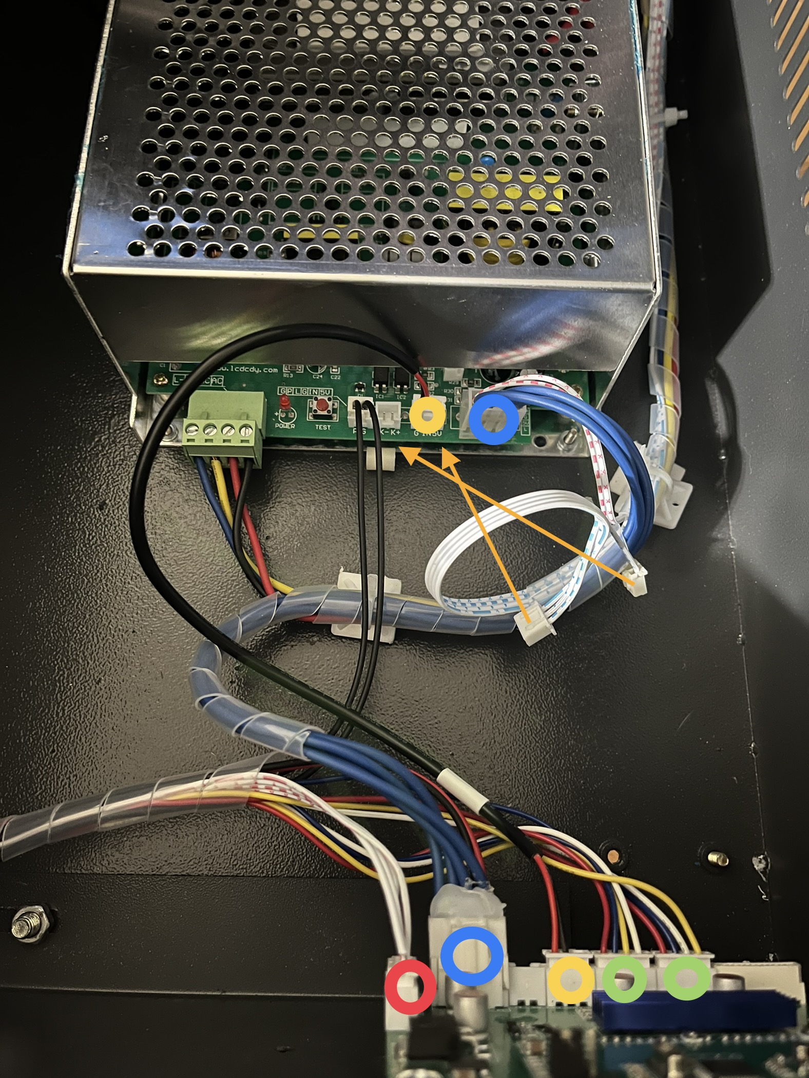
The red and green dots above are for limiter and x/y. The blue dot indicates power. The yellow dot is for the “laser control” wire on the new controller.
The disconnected wires with orange arrows used to power the top panel display (these are no longer in use and are replaced by the “laser control” wire.
By meter to check pwm, do you mean the ammeter on the top panel? I’ve noticed when the laser is in use it will move, but I’m not sure if it is functional, or not after replacing the controller
I’ll be picking up a meter today while im out getting lunch.
The red and black wire are both connected to “IN” and “GND”
The display panel does not work because it received power from where the “laser control” wire is now connected. At one point i had one of the two wires with orange arrows above connected to the K-,K+ header, but have since disconnected it. The ammeter began to move after doing so. I’m assuming it was confused between two inputs. it is hard to tell the reading because it moves very quickly, but it does seem like there are varying readings according to power level set in lightburn. i will take another look this afternoon after work meetings. I’ve run the attached file at multiple power settings, but no difference between any of the three squares no matter setting.
This is likely for the Test fire button. It shouldn’t have affected the ammeter though I don’t think unless these were somehow run in series.
What were the two inputs?
Those settings should have made a noticeable difference. In fact, a layer at 1% should not have fired at all.
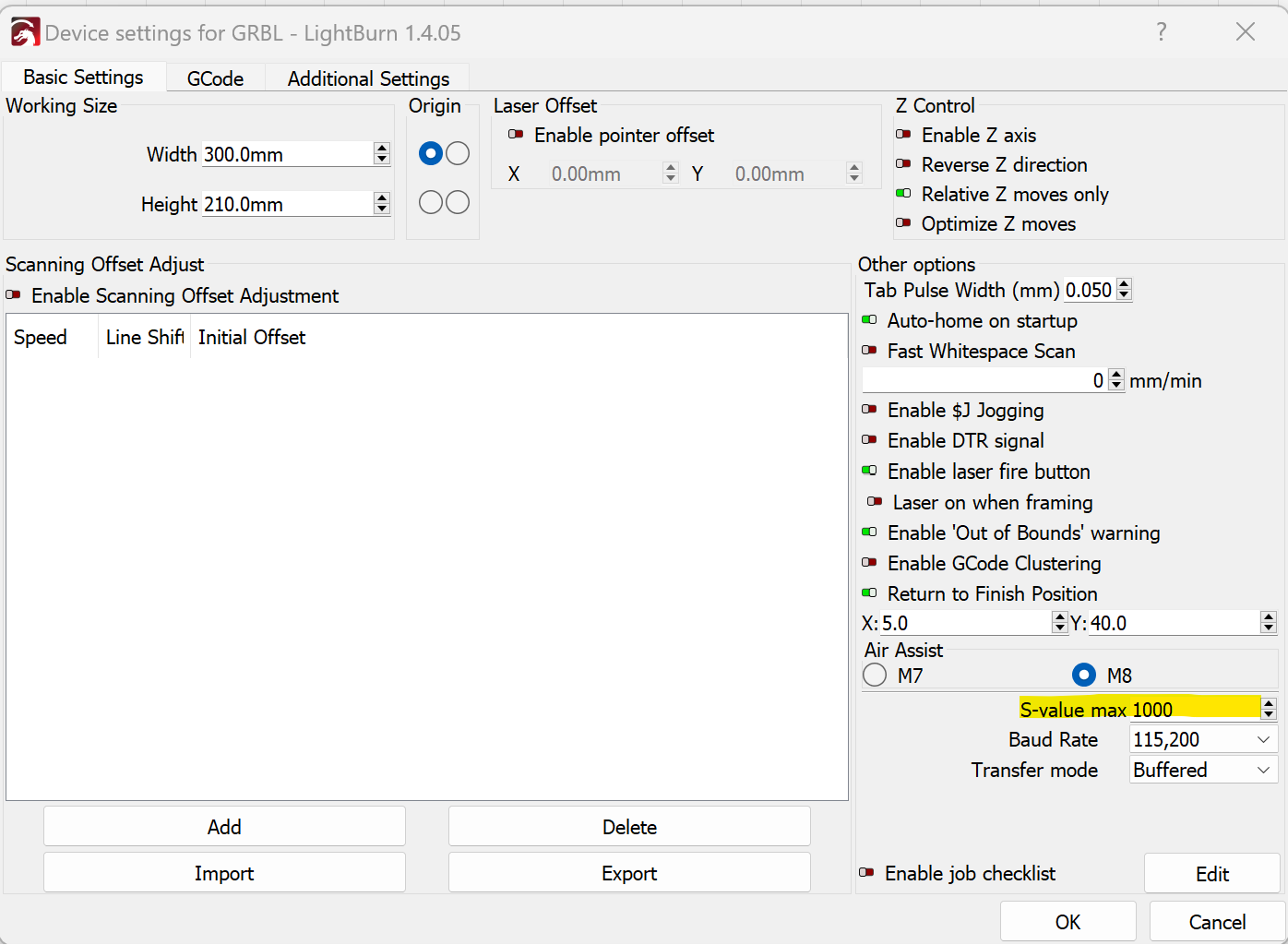
Your Origin in Device Settings is a bit unusual. Does your machine jog correctly? As in up moves up, down moves down, left moves left, and right moves right? Are your jobs burned where you expect them and in correct orientation? I’d expect jogging controls up and down to be backwards and your burn orientation flipped vertically.
Normally your machine would have Origin at bottom-left.
That’s correct.
It’s almost certainly not going to be a settings issue at this point.
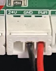
Once you have your volt meter test the PWM out pins on the controller at varying power levels. 0% power should equate to 0V. 100% power should equate to 5V. 50% power should be 2.5V.
If that works, then test LPS. Reattach the front panel controls. Set power to lowest possible and push test button. What is the ammeter rating? Gradually increase power and continue testing. Do you see increased current at increased power settings?
i think you may be correct and they are wired in series.
The two inputs were the new “laser control” wire and the front panel display wire in k- k+. I figured it was confusing the ammeter.
Yes, i opted to set the origin on the top left. initially the machine did not move correctly, but i was able to troubleshoot the issue and resolve it. Everything burned where they should be and not backwards.
I did not realize monport had a bad reputation. To be honest i impulsively bought the machine out of boredom one weekend. If there is another controller upgrade option that is as simple to replace this one with im all ears.
Is what we’ve been doing here your idea of simple?
I think if you want help from Monport, then you should set it up as specified by them. They will always put you last behind customers that have a recommended [by them] setup.
We know how the control signals work with these devices. Although the K40 supply is a bit different we do know what they do… With a voltmeter we can tell what is or isn’t there… This may help us figure out what they are doing.
@berainlb I think these are using the pwm on the IN of the lps and running the L pin though the laser enable console switch… I had suggested this before, but many like the other configuration. Have no idea how they actually limit maximum current to sync with percentage power in the software.
I haven’t been able to get a straight answer from the 3 or 4 people I’ve seen with similar, I think the same issue.
I don’t know how long Monport has been around, likewise for Cloud Ray and OMTech. I’ve gotten my two machines, one from each, so I get email from the sites. I used to think Monport was pretty much like the rest of them. However I’ve seen some real questionable setups that could not have worked correctly when they left the factory… so I’m starting to wonder.
One thread advised he had so much trouble with OMTech that he went to Monport and has been very happy. I got my fiber from Cloud Ray and they did fine, but I’ve only had to ask them the steps/rotation for my machine. They answered it in a couple days. I also saw a post where they got a 90W Reci and it’s output is clearly out of TEM00 mode, but they refuse to swap it out. I’ve heard similar for OMTech.
They are in China, so there is virtually no recourse. After all this time, I think it’s just a crap shoot with whom you get when working with these companies. There must be a majority of good will as they are still selling them.
@jkwilborn I’m terms of functionality it hasn’t been easy. I guess I meant as far as the actual connections go, is there another controller that performs better and does not require a lot of rewiring
Picked up a multimeter and ran a quick test with 2 rows of squares at 1%, 25%, 50% and 100%. There were varying degrees of voltage, but not exactly at 2.5 for 50% or 5v for 100%. The voltage ranged at .1, 1.2, 2.3, and 3.4 for each of the squares above. Does this mean the correct reading is not being delivered from the controller?
From looking at the squares on a scrap piece of wood it seemed like the laser was delivering too much power. I’m very new to this, so seeing the voltage not meet the assumed voltage based on percentage set in lightburn is confusing. especially because to me it would seem that if the 100 percent setting is not at 5v then why is the material burning.
Will try with original panel connected this afternoon when I have more time
If you read 100% power as 3.3V then that’s incorrect. It should be real close to 2.5V at 50% pwm. It should read a percentage of it’s range voltage, since it’s only off or on. 20% of 5V is 1V.
Many of these boards are 3.3V and need a voltage translator or some hardware to get a 0 to 5V ttl type voltage.
I had thought that was mentioned…
Confirm you get 3.3V at 100% and 1.65V for 50%… 20% about 0.66V.
There are several options for drop-in replacement.
The common ones include:
Mini-gerbil
Cohesion3D
Omtech K40+; I believe I’ve seen a newer Omtech GRBL based card but can’t find a link to it
There are a bunch of others. Since your machine doesn’t use a ribbon cable you could use any of those cards.
Monport is newer to the scene with some options.
There are people that use more generic cards and adapt it for use in the K40 but typically bit more work in terms of wiring and possibily having to swap out limit switches.
This sounds like the same issue we’ve seen from another couple of users where instead of using 5V logic the board is using 3.3V logic which just won’t work properly with the machine.
However, based on what you’re getting this should be enough to get power modulation from the LPS. You’ll just never get full power.
This Topic is worth review in terms of the 3.3V vs 5V. TLDR: ask for a new board without the issue.