Power supply output current and laser power

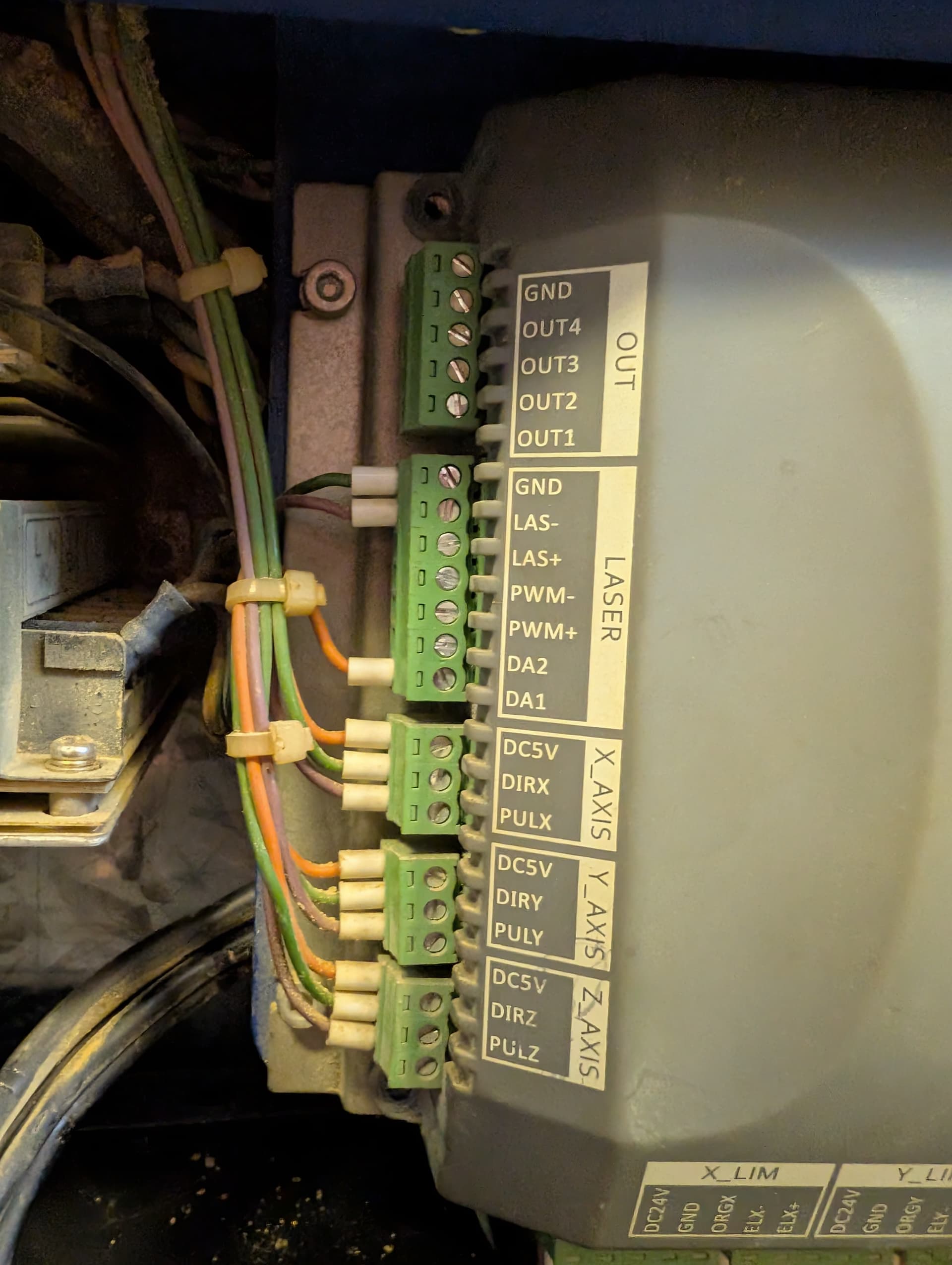
We have an old CTR TMX65 using a Leetro MPC6565 control board which we use to cut models out of 2mm and 3mm MDF.

Our cut settings have remained the same for some six years; we use 80% power for a through cut and just 6% power for a light surface etch for some surface details.

A while ago we noticed the surface detail wasn’t clear. To achieve the same sort of clarity, we had to increase the laser power from 6% to 24%.

Thinking that this might be the laser signalling the end of it’s life, we ordered a replacement. The replacement showed the same problem, so we thought it might be the power pack. This also showed the same problem - 24% power required for a very superficial surface line.

We’ve now tried four power packs and three laser tubes (the original plus two replacements), one of which the supplier did test and was honest enough to say there were some irregularities - but even a second replacement still shows the problem.

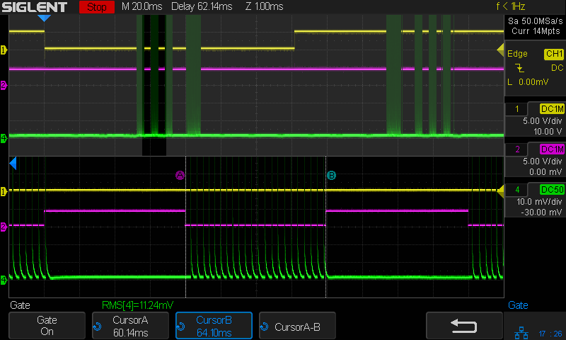
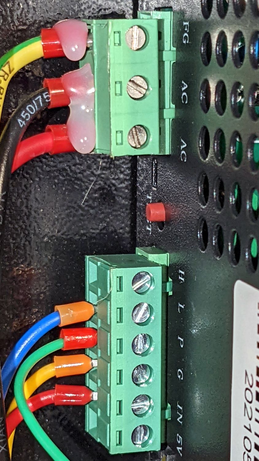
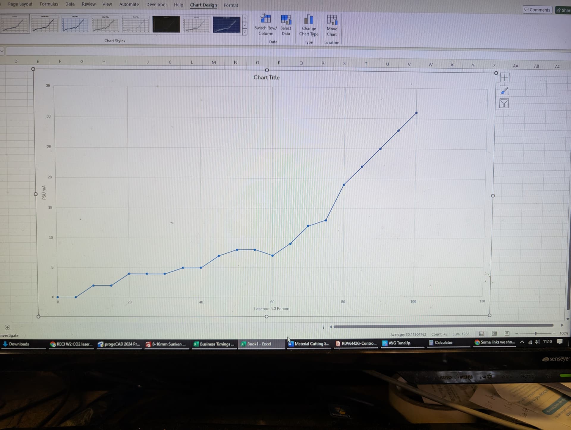
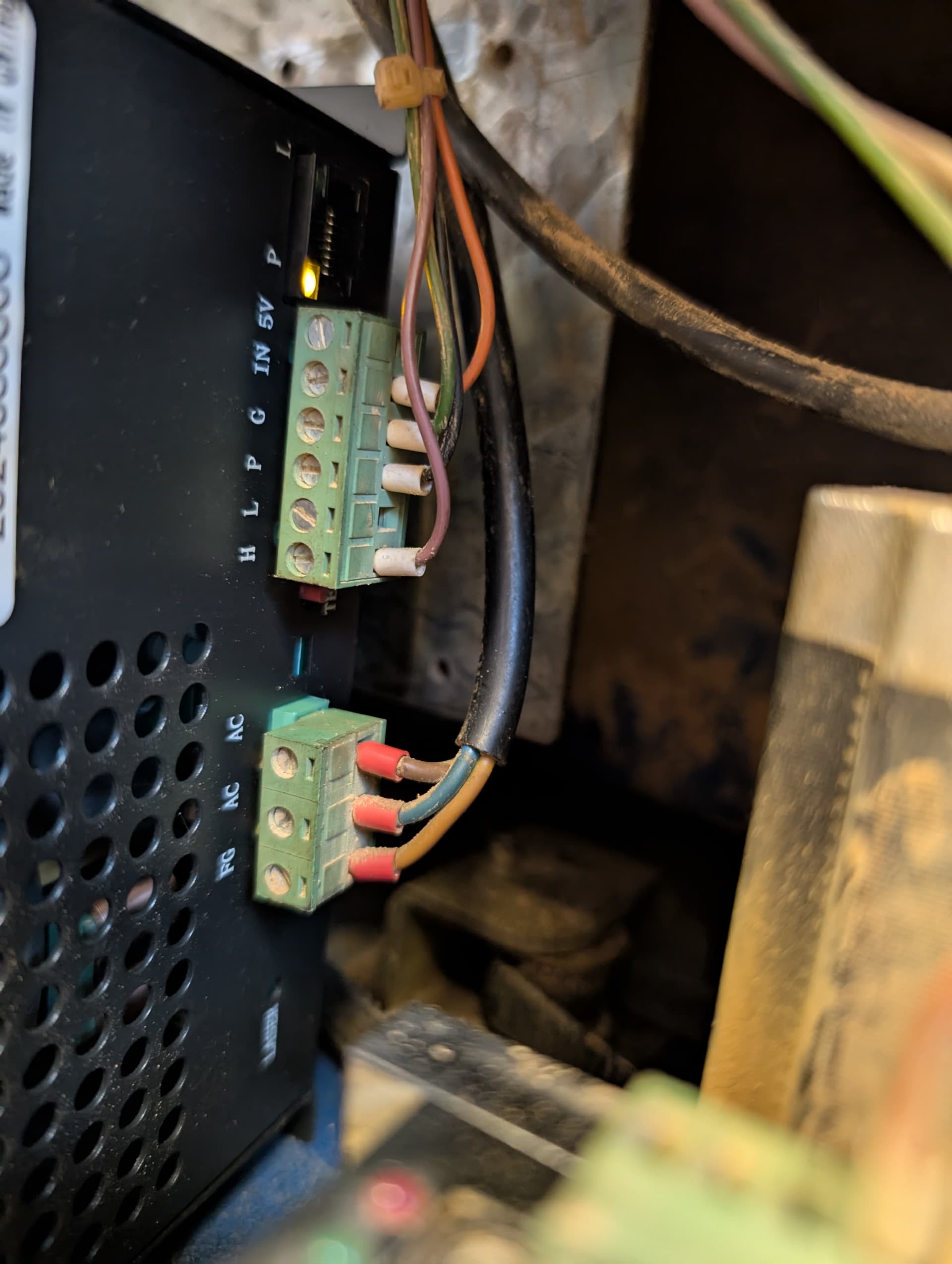
I’ve noticed something during trying to fix this problem. There’s an LCD panel on the power pack that shows the power output when the laser fires. It comes set to about 12mA but is rated up to 30mA maximum. We can set the output current with a screw on the power pack, and we set it to 24. However, when we set the power output (from software) to 6% - nothing registers on the laser. 6% of 24 is about 1.5 so it really SHOULD be registering. We then looked at some higher power settings in software and none of the “percentages” matched the current drawn shown on the power pack - the power pack always read lower than expected.

So, long preamble, but we were wondering two things;

  1. is the relationship between 0-100% power in software and the current drawn on the power pack linear? ie if we have the pack set to 24mA maximum, should 25% show 6mA, 50% show 12mA, etc?

  2. If the answer to the above is “yes”, are there any other components that might have failed that could be causing us this problem? Something on the board perhaps?

Hope someone can help, this has been driving us nuts for weeks!

Approximately, pretty much, kinda-sorta.

I did some measurements of RMS tube current vs. PWM percentage a while ago and came up with a graph:

The tube doesn’t fire below about 10% and the mush below 30% comes from the very spiky nature of the “DC” tube current overwhelming the scope’s RMS calculation, as in the green traces at 10%:

Typical CO₂ tubes don’t fire below about 10%, so perhaps your old / original tube was more enthusiastic than its replacements.

Set the controller for manual pulses and try power levels from 6% up to maybe 15%. The tube will probably start firing around 10%, but the percentage depends on temperature (and probably moon phase), so run a few percent higher as a comfort margin.

I assume the tube cathode wire (typically skinny with black insulation) goes directly into the power supply, rather than being connected to anything else. AFAICT, that lead goes to a current sensing resistor inside the supply, so if it’s connected / shorted to anything else, that will affect the supply’s current regulation.

It is possible the controller’s PWM output has gone bad, but that seems unlikely. Set a multimeter to measure DC volts and, at the laser power supply, measure between the IN and G terminals (the laser need not be firing, so you can open the lid):

The voltage should be between 0 and 5 VDC, roughly proportional to the power percentage:

  • 25% → 1.3 V
  • 50% → 2.5 V
  • 75% → 3.8 V
  • 99% → 5 V

If that’s what you measure, then the controller is telling the supply what to do and the supply isn’t doing it. Having gone through all those replacement supplies, it seems unlikely you have a(nother) dud, but it’s possible.

Nowhere do you mention inspecting the mirrors & focus lens. Any problems there will certainly affect the results (but obviously not the tube current!), so take them out, give them a careful examination, then clean / replace as needed.

Good hunting!

My boss is obsessive about cleaning and polishing the mirrors (he’s an engineer by background, so seems to have a polishing cloth in every pocket).

We’ll get to the other stuff you’ve suggested on Thursday. Thanks to all.

You’ll probably find I misspoke on “you can open the lid”. If the lid interlock is wired to the controller, it will refuse to fire the laser and you won’t measure anything.

You can turn off the power supply’s AC input to prevent the laser from firing. On my machine, the AC line goes through the key lock switch and the controller knows nothing of it.

Our relationship isn’t linear until we ask for 80%. Something is very wrong I think .

(Power requested as % on x axis, reading on the powerpack meter on y axis)

Just done your suggested multimeter test.

If we ask the software for

100% we get 2.0v,
75% we get about 0.96 to 1.2v
50% we get 0.75v

But here’s the kicker; after the cut is finished, the voltage across those terminals doesn’t drop to zero, the value stays the same as whatever we requested last.

This doesn’t sound right to me.

Assuming I tested the right pins!

For reference in the above picture;

“IN” (orange wire) is connected to DA1 on our Leetro MPC6565 board.

“G” (green wire) is connected to GND

“P” (black wire) is connected to our cover safety switch (we think, it’s hard to follow)

“H” (brown or purple depending on lighting) is connected to LAS-

Because the LASER block on the controller has PWM+ and PWM- terminals, it looks like the machine is wired to use an analog power control voltage from DA1, rather than the usual digital PWM signal from either of the PWM terminals. That is surprising, but not unheard of.

However, the shiny new HV power supply (almost certainly, unless you know otherwise) expects either:

  • A digital PWM signal between 0 VDC and 5 VDC
  • An analog voltage between 0 VDC and 5 VDC

The 2.0 V analog signal you’re seeing at 100% power will deliver less than half the supply’s maximum current to the tube.

If 2.0 V delivered full power from the original supply (which I believe is not the case), then the other voltages suggest trouble. The 1.1-ish V at 75% is too low (it should be 1.5 V) and the 0.75 V at 50% is much lower (it should be 1.0 V) than you’d expect with a simple linear relationship between 0 V and 2 V.

A simpler explanation is that the controller’s analog output has failed: it should deliver 5 V at 100%, but no longer does. That’s consistent with the original symptom of a sudden power drop (the analog output lost its mojo) and my assumed behavior of the original power supply needing 5 V for full power.

For diagnosis:

At the controller, move the orange wire from DA1 to PWM+, which should deliver a 0 to 5 V digital signal to the power supply.

At the power supply, measure the voltage between IN and G again with power settings 25%, 50%, 75%, and 100%. If you see (about) 1.25 V, 2.5 V, 3.75 V, and 5.0 V, then the laser should be delivering full power again, because the controller can still produce a 5 V PWM digital signal.

If that’s the case, slam the hatch and you’re back in business … :grin:

Thanks Ed. This will be first thing in the test queue tomorrow.

We’ve turned the power supply’ s mA way down so we don’t end up putting 50mA through the tube!

One last point…should the terminal be still carrying the voltage when the cut is finished?

Btw where are you in the world…we are in England.

Also, other than ensuring the power isn’t too high, is there anything else that could ruin our day? Polarity etc…? I note for example your block connects to L where we use H… .

Edit; at the risk of sounding like I know something, does L and H refer to “pull up” and “pull down” in any way?

Also (also)…if we used the multimeter method at a given power setting and measured the voltage, if we left everything connected as it is now, fired again, but measured the voltage from the PWM pin on the card to the GND on the power supply…would that be a good (and safe) test to see if the PWM output is more as expected (ie about 2.5v for 50%), the same “broken” value or indeed if it doesn’t put out anything at all?

My last (I hope) PS …

This machine does NOT use Lightburn. It cuts with “Lasercut”. I have no idea if we have to edit something to activate the PWM+ instead of the DA1, or if the controller just triggers all outputs and hopes something is there to respond! Thoughts?

OK, more confused than ever.

Power set to 50%
Measured DA1 voltage as 0.75v,
Measured PWM+ voltage as 3.7v

Power set to 100%
Measured DA1 voltage as 2.0v
Measured PWM+ voltage as 3.7v.

The PWM to Ground voltage measures 3.7v the second we turn on the machine.
When we used DA1 the powerpack LCD read 4mA at 50% (we turned the output right down via the screw on the powerpack).
When we used PWM+ it read 18mA.

Not sure what to do next!

We are sourcing a second hand replacement control board (MPC6565 or MPC 6535) from a contact who says he has a few “lying around”. It’s obvious the voltage control on our board via analogue is unreliable and via PWM may be the same, or just may require some settings changes that we don’t know about yet.LaserCut does have a “machine settings” screen, but the “manual” is less than helpful; there is a section for “settings”, but it may as well just say “This is where the settings are”.

I’ll continue to report out progress or lack thereof. Odds of Happy Dance seen slim right now…

The PWM output should stay low when all the cutting gets done, but Ruida controllers seem to leave it running at whatever the last setting was and use the L-ON signal to shut off the current. What that controller does is entirely up to it.

That controller seems to bring out both polarities for the LAS (which I think corresponds to Ruida’s L-ON) and PWM signals.

On the power supply, those are the digital enable signals: H is active-high and L is active-low. The Ruida L-ON output is (by default) active-low, so it goes to the L power supply terminal.

On your controller, assuming the LAS- terminal is the active-low enable output, it should go to the L terminal.

Using the wrong polarity means the tube will fire when it shouldn’t and not fire when it should, which will quickly become obvious.

Indeed!

Based on your measurements, it seems nearly all of my assumptions about the controller are wrong and, thus, most of the things I’ve suggested are wrong.

:frowning_face:

The voltages on the outputs suggest they’re Original Gangster TTL, with a voltage around 3.7 V when they’re high, rather than today’s CMOS outputs reaching 5.0 V. That means the controller’s analog & digital output signals will not properly drive the new power supply’s IN terminal, because the voltage simply isn’t high enough.

The controller worked with the original power supply, because the supply was designed to run with that hardware and those voltages. Newer power supplies will not work with OG TTL levels, even though they use that nomenclature.

Our collective assumption that the original power supply failed still seems reasonable, but swapping in a new supply built with today’s circuitry will not solve the problem. If you can scrounge an original power supply that’s still in working condition, it should drop right in.

None of that has anything to do with LightBurn or the controller’s internal configuration and everything to do with the hardware inside both the controller and the power supply.

Which will almost certainly arrive with configuration settings completely inappropriate for your machine, so it will not be an easy swap. You must copy the existing config to the new machine by looking-and-typing, unless the control software lets you save-and-restore the settings in bulk.

It’s remarkably easy for me to spend your money, but that old machine may have reached the end of its useful life. While you could replace the controller, power supply, and possibly the stepper drivers & maybe even the motors, it’s not obvious to me doing so will be the most productive use of your time & money.

Halfway up the Hudson River in New York in Poughkeepsie, a place nobody ever goes by accident.

It’s been a looong time since I traveled your way; roughly when TTL was a thing, come to think of it.

I wish I was on a proper PC for a few reasons, those relevant right now being that phone keyboards play merry hell with my Parkinson’s and it’s almost impossible to use the “quote” feature. The first will bother me more than it does you (typos aside), but the second means you’ll have to guess which part I’m replying to.

We realise we are asking a lot expecting help on a non Lightburn supported Laser and (ancient and much maligned) LaserCut software - which does however support storage of config files that we can indeed save to the machine, so hopefully our not-so-new board will be talking our language in a single click.

We would both like to say regardless of outcome we have been extremely impressed by the help we have been offered here, and also hope our suffering will be of use to others

Now on to our specific problem (again). Yes, it’s a concern that both the DA1 and PWM outputs seem incapable of producing 5v. I’ve some history tinkering with Arduino boards (hence my rudimentary knowledge of “pull-up” and “pull-down”) so I’m used to getting my 5v reliably, thank you very much, and it was a bit of a shock when the PWM+ didn’t deliver. Really thought switching to that would be our “aha!” Moment, but it turned into just another head scratcher. It gave the same behaviour I’d associate with a “floating” input; with the machine running, the voltage was very variable, spiking at 15ish at one point (my Parkinson’s may have to take some of the blame as we only saw that once).

We are connected to LAS- on the controller, but H on the PSU. There are settings in LaserCut that would indicate it should be LOW active (though “indicate” is based on interpretation, the manual being utterly useless)…but since I am assured the H cable has never changed, that just swaps the “why doesn’t it work anymore” question for a “Why did it EVER work” question.

And now it seems we may be trying to get a new fangled square 5v peg into an old fashioned round 3.6v hole.

Sigh I’m close to offering you airfare to come fix it. As they say, “you don’t pay them to push the button, you pay them to know what button to push.”

I jest, we’re a small outfit, but if I win the lottery I’ll be offering you warm beer and judgement based on what your grandfather did in the 40s in a heartbeat!

We persevere…if using the wrong powerpack is the problem, are there real technical terms that we should search for to replace “OG”?

Also …TTL?

Edit: is the “L” for “Logic”? In which case I sort of understand again because of my experienced with the Arduino chips. 3V and 5V logic were common terms in that area for different systems, but there were converters available. Could something like that be used here?

Link relevant;

(Posting this) as a new reply as it’s just me trying to improve my understanding;

Active High vs Active Low I interpret as high means 5v = laser on and low means 0v = laser on (with I assume some tolerance built in).

Is that correct and if so does it change what the controller sends to the PSU in terms of percentage power demands (eg is 0-100% represented as 0v up to 5v in the first case and 5v down to 0v in the second), or does that stay the same (ie is a separate “channel” for want of a better word)?

Thanks!

TTL Wiki

If the input is for the water protection and the signal at the controller is correctly in a low state, that input is active, so active low.


If you notice, the ON threshold is about 2V, so a 3.3V cpu could drive these TTL level signals on/off properly.

The IN input is a different animal in that it’s really a dc control voltage. PWM is converted to analog inside the lps. Many commercial laser controllers have an analog power control output. Requiring a signal range of 0 to 5V (hence the term PWM TTL). The ttl signal can’t reach 5V unless it’s driven from a 5V source.


You can put a voltage translator in circuit. A cheap one as it goes one direction.

These are easy to build if you want to.

:smile_cat: