Hi I was woundering if a third target option could be added to the Print and cut feature, as this would make the print and cut work extremly well, as to automatic scalling and rotation of the shapes position to be cut. we do a lot of uv prints for our laser customers that all Use lightburn and this would be a huge improvement to the Print and Cut feature. as it would not only scale the cut file to the print file, it would also correct and rotation of the printed shapes that would be laser cut. and make them cut extremly accurate each time if the targets are lined up well. One extra target added is all that would be required. Im sure others would love this added to a release in the not to distant version, hopefully its allready in the addition list of improvements on this awesome software, I would be happy to be on a group of testers as well if possible.
There is feature suggestions up next to the search tool.
You can post a suggestion and the forum users can vote on it.
Good luck
![]()
Thanks, just posted there as well, lets get some votes happening everyone 3rd option for target in Print and Cut Feature · LightBurn
I’m not following what the benefit would be. How would a 3rd target enable something that’s not available today? Scaling and rotation already work with the current solution.
Am I missing something?
it assumes your laser is cutting the exzact same measurement as the print in X and Y, if its a little off calibration between the print and the laser it fails to work well. 3rd target would eliminate this issue completly
This isn’t actually true. There are two modes for print and cut. One mode offers scaling.
Also, how do you see a 3rd target being used? It’s not clear to me how it would contribute to the process. Then there’s the added complexity of reconciling alignment differences across 3 points instead of just 2.
scaling and rotation dont work in combination ive found, its either one or the other as it gives you 2 options, scalling and no scalling, “No Scalling” will pick up a rotation, as long as the print and the cut file are the same dimentions and the laser is calibrated with the printed item. if its not you have issues,and for the scalling option, it will work if you have targets on the diaginal corners but the print needs to be perfectly placed square in the laser. lets just say if the printed object is a 1mm out on the y axis, and the laser is a few mm out in the the other direction, how does it work out if the image is slightly rotated or not and the scale, it cannot. the 3rd target would give it accurate scalling a 3rd reference point and fix the rotation, scalling in the x and y axis combined into one option even if the print was a completly different size to the file in lightburn. and even if the laser isnt calibrated to the physical print
I think this is the crux of discrepancy in understanding. Alignment with scale will handle both rotation and scaling. The distance of the targets is used to determine scaling. The relative position is used to determine rotation. The order the targets are selected determines orientation.
Did you run into an issue with concurrent scaling and rotation?
scaling and rotation do not work in the same option, and both only work if laser is calibrated to correct measurements, and then the other spanner in the works is if the physical print is a different dimention, to fix all the above issues a 3rd target would correct all senarios along with rotation
Not sure what else to say as it seems you’re simply rejecting what I’m saying about how it can work.
Perhaps a demonstration would be more persuasive.
Exhibit 1:
Screenshot of LightBurn showing the distance between registration markers at 484.72 mm. Note the yellow highlight at the bottom of the screen. Also note the orientation of the design.
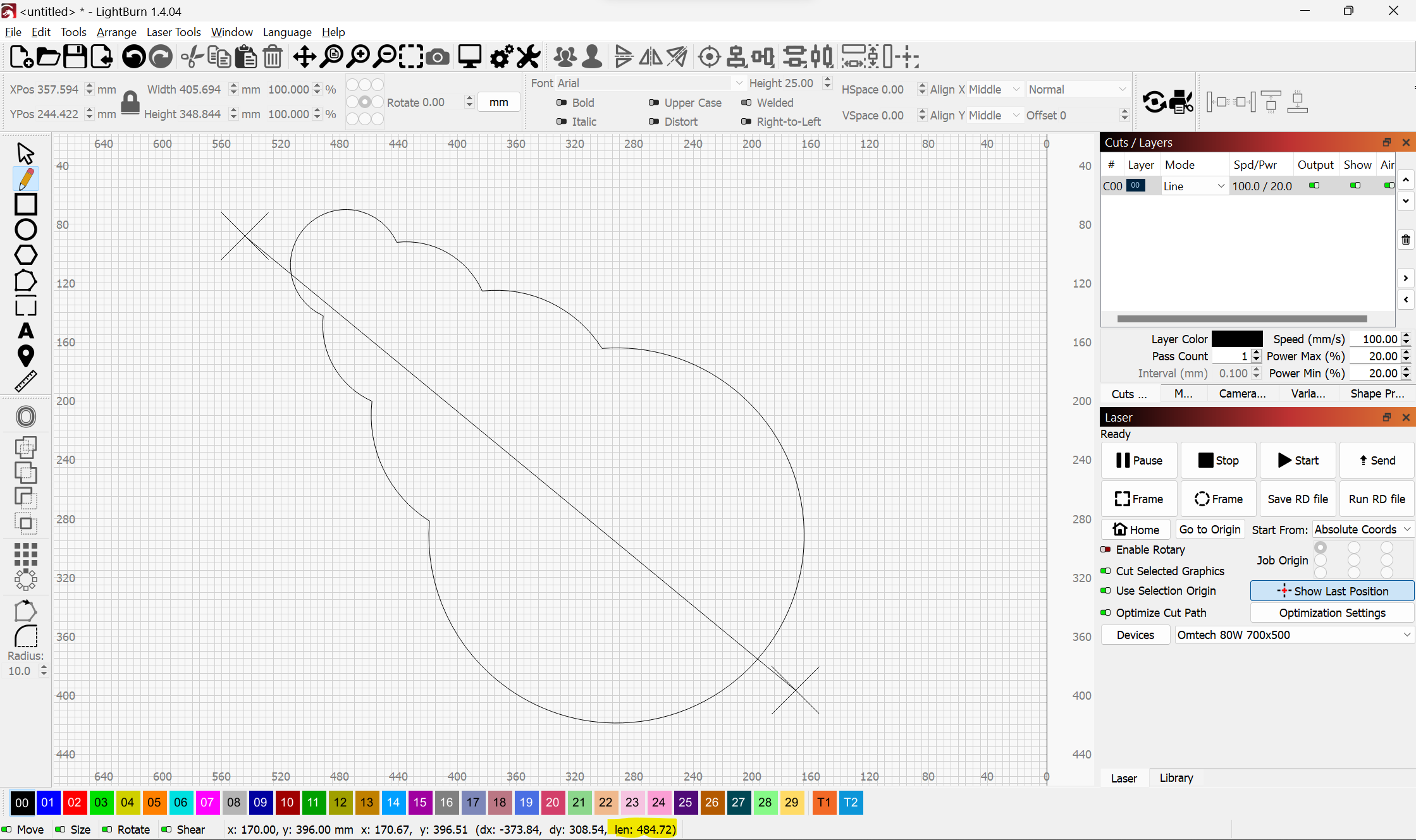
Exhibit 2:
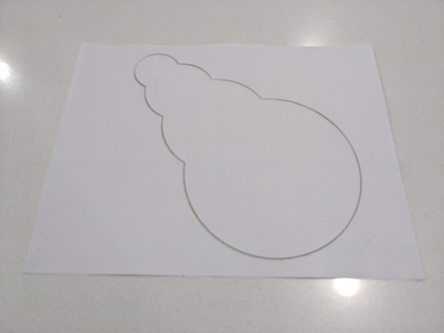
Printed design. Apologize for the light markings but you should be able to make out the faint outline. Measurement shows distance between markers at roughly 267 mm.
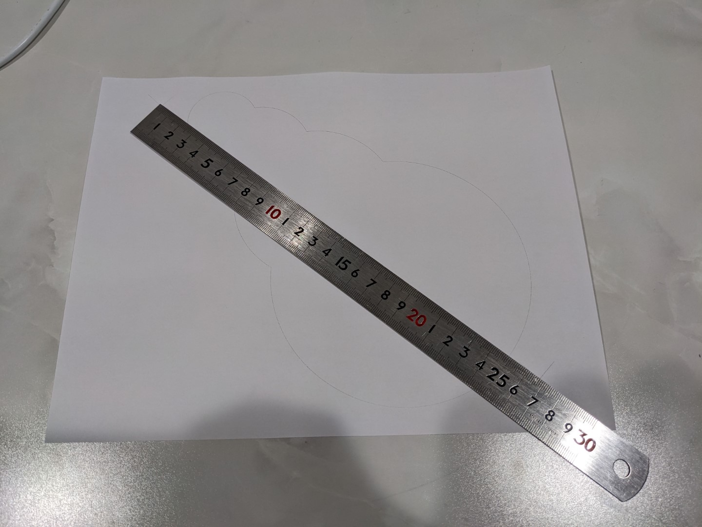
Exhibit 3:
Print placed on bed. Note the ~90 degree clockwise rotation of the print vs the design.
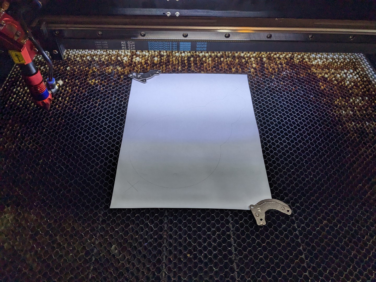
Exhibit 4:
LightBurn screenshot after print and cut alignment with scaling.
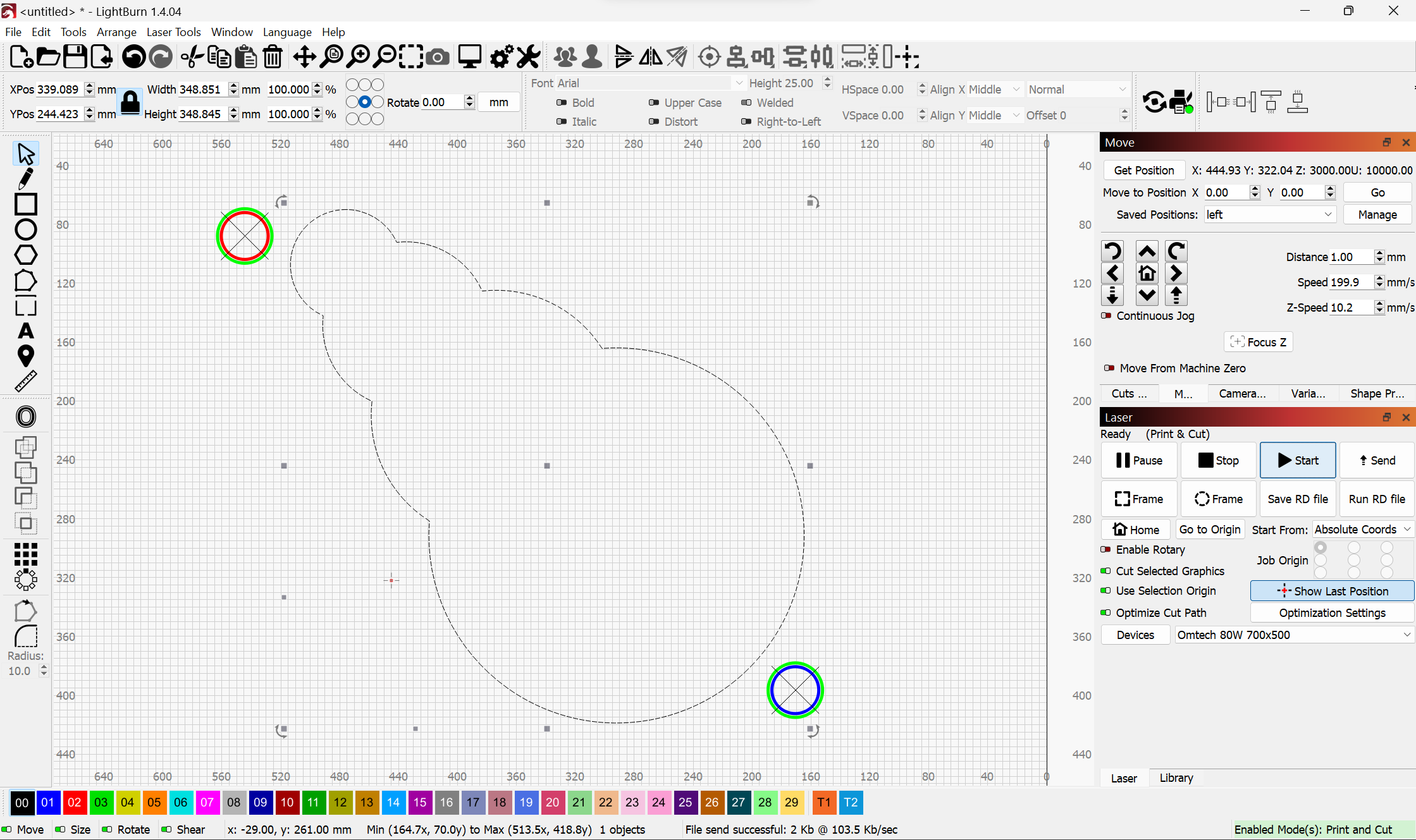
Exhibit 5:
Post cut photo of print. Note how both the rotation and scale were accomplished with a clean cut.
I also have a video of the burn in process if you’d find that compelling.
Try a uncalibrated laser to printer, or adjust your x axis so its out a little in steps per mm. then placing a print and cut in on a random angle, then try on the scaled and unscaled options in lightburn print and cut, you will then quickly understand my point and why a 3rd target would work perfectly.
What you’re describing would be an additional dimension for print and cut. I was specifically addressing scale and rotation which were the functions that were stated as not working concurrently.
What you’re describing now with a situation where one axis is out of calibration would be a form of distortion correction which print and cut does not do. I question if print and cut is where you’d want to address this. And if you did, what’s the limit? Why not other forms of distortion?
Is there a reason why calibrating the axes is not the correct answer for what you’re doing?
When I used to wide format UV print on a 200K printer and cut with a 150K CNC cutting table and a 5K camera, we mostly used 3 targets. The table manufactuer recommended it. Sometimes we would cheat and use 2 targets, because it would save time. We could get away with it when cutting stock under 0.024". Anything thicker, we used 3 targets. That cutting table with camera was considerably more accurate than a budget laser with a camera. The OP has a point.
Maybe @DazzlefieCreations comes from the GIS world, here “we” have always used 3 measurement points to determine/find the coordinates of a given point in the landscape. (before GPS/total station)
It also took me a little overcoming at the beginning to “accept” or better said, understand that 2 points are enough.
In LightBurn we have X and Y which are static and pre-programmed, this does not exist in the free nature, - unless there are marked coordinate points ![]() and, the height of a point in LightBurn does not normally have to be taken into account either. That is probably the main difference between 2D and 3D.
and, the height of a point in LightBurn does not normally have to be taken into account either. That is probably the main difference between 2D and 3D.
I don’t know how with very large machines or cnc milling machines, but with my small 400x600 system, print and cut work great and are very accurate with “only” 2 points/coordinates.
In what way did thickness impact accuracy? Was this possibly a parallax issue with the camera?
Note that LightBurn doesn’t use a camera for print and cut. It’s accomplished with the laser pointer (or more precisely stated based on position of the laser itself). Parallax is not an issue with this method. Precision is within the tolerance of stepper motor movement and the ability to resolve the pointer against a printed target. In any case, sub-millimeter.
I understand the potential value add for the latest scenario OP is describing. It’s just an additional dimension to what was being described earlier when the discussion was limited to rotation and scale. OP would like print and cut to handle the case where the picture has been distorted only in the horizontal or vertical direction. OP is correct that print and cut doesn’t handle that today.
It’s not clear to me that it necessarily should handle that but I can see a case being made for it.
UV lamps will shrink and distort substrates. It always seemed to be more of a problem for us with thicker material and 2 targets. The software would also auto scale and rotate the cut file.
Did this use a head mounted camera to do auto-registration?
Yes. This is a video of the system.
https://www.youtube.com/watch?v=OY0FOWVzQks&ab_channel=Z%C3%BCndSystemtechnikAG
The head mounted camera was adjusted for focus height so I don’t see parallax being a major issue.
3 registration marks could reasonably correct for linear distortion. The video makes mention of correcting for all common printing distortions so curious what else it does. I can’t imagine it handling pincushion, barrel, or other more complex distortion types.
If you notice in the video, they use 5 or 6 registration marks. We would use 3.
They have an updated system where the camera is mounted above the table, and it takes a picture of all registration marks at once.
