**Was the file from today the same file from yesterday after corrections? Or totally different designs?
** Different designs, different files, but similar layout.
Blockquote
I use the scaling in all of them, the acrylic can shrink a little when heat pressed and sometimes they don’t print exactly to scale(printer operator & software issue) I assumed the scaling would correct for these issues, if not, that may be my issue.
Does the acrylic shrink uniformly vertically and horizontally? Or does it favor one direction over the other? If you were to print a square would it remain a square or could it become rectangular.
Print and cut accounts for scaling changes but not distortion changes. I think you could manually adjust for distortion before the cut if you created registration marks on the print that you could measure. So for example if your 8x8 designs becomes 7.5 x 7. You could use the width and height adjustments in LightBurn to resize your entire design. Then use print and cut alignment to cut to the distorted shape. In this case you could use the non-scaling method since you’ve manually scaled.
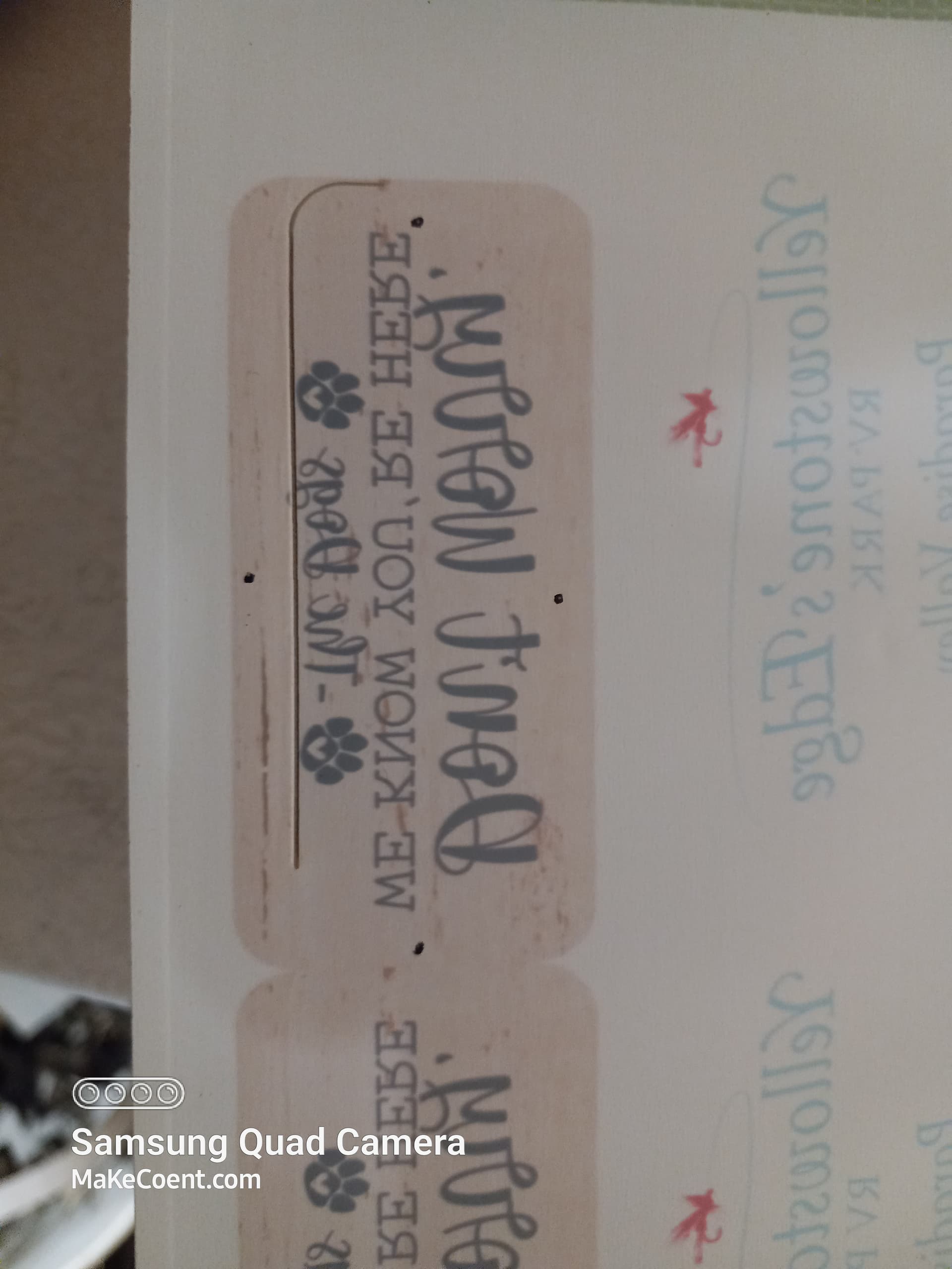
Here is another pic of the issue in question. The 4 black dots are pulses on the edge of the shape in lb, you can see how far off the cut is. The pulses were made by positioning the laser head to the edge of the object with the position feature(not manually).
The object is approximately 1.125"×2.75".
The acrylic shrinks uniformly, the images aren’t distorted. I haven’t measured it, but it’s not much, maybe a few hundredths of an inch on a 12"x12" square.
I’ll build my next file with the registration marks evenly spaced, directly across from each other. That way I can easily scale the cuts by measuring the distance between them. I assumed the scaling would adjust for this in print and cut, as the other option is unscaled.
This would make sense for the files that are off different from top to bottom, a distortion or size difference would account for that. I wouldn’t think it would cause the object to cut in a different location, though.
I took a close look at the design files. At first glance they seemed fine but then noticed an issue. But not the same issue as what you’re seeing so curious.
Notice that the cut layer on the bottom shape is set too high? The same issue extends down the design for that column. Everything else looks correct.
This is not where you’re seeing an issue, however.
A couple of notes. Not directly relevant in this conversation but for future reference:
the father apart the registration marks the less tendency for error. I know yours are quite far apart in real world measurements but something to consider.
Not sure why but the image file and the svg file seemed to come in at radically different scales. Wasn’t hard to correct but thought that was interesting.
You’re saying that the dots were placed along the cut-line in LB? Do the dots appear where you expect the actual cuts to be?
Doesn’t seem like this would be the major culprit at that level of shrinkage and without distortion…
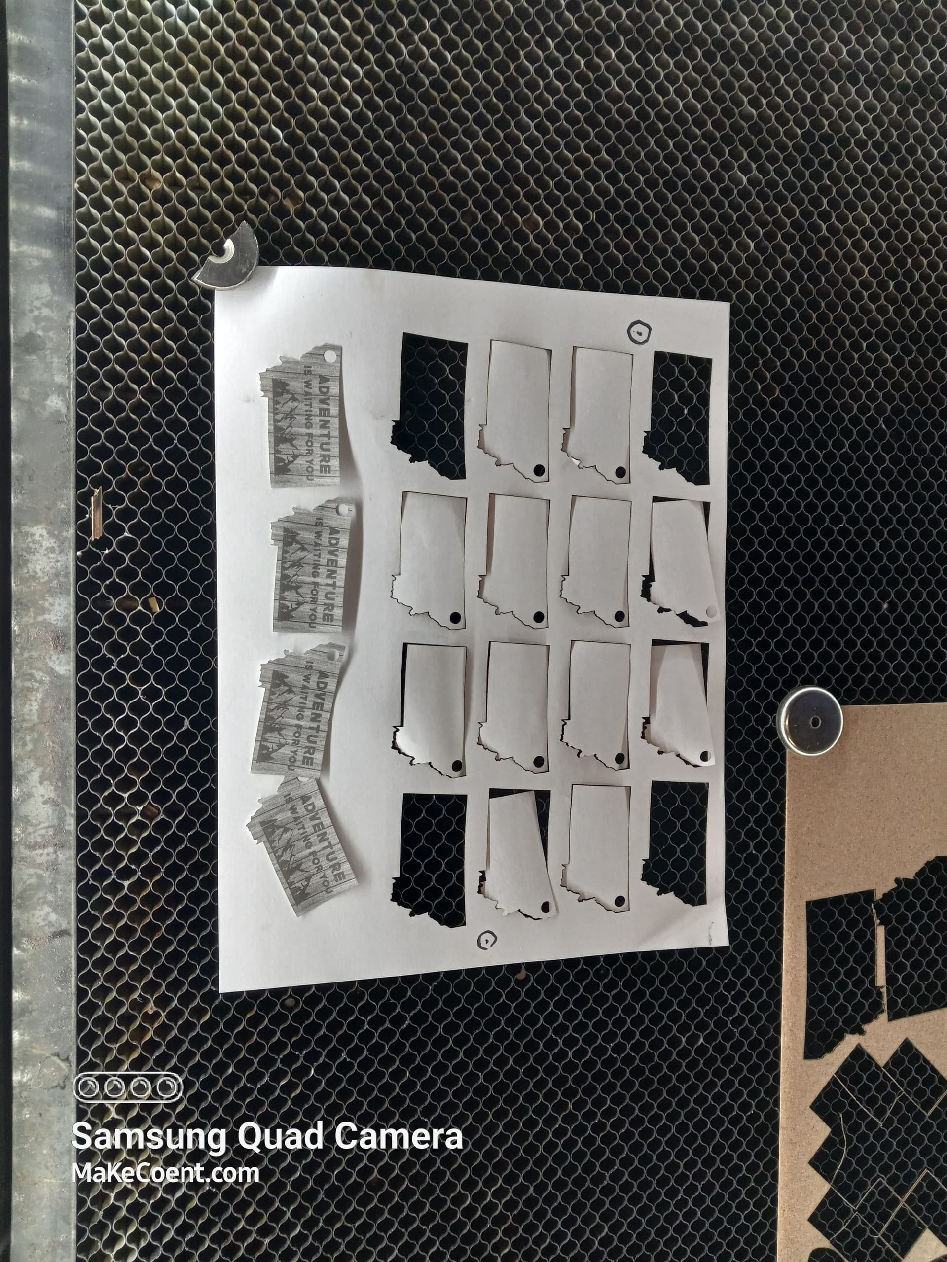
Are you able to do a print and cut with this exact design on printer paper or something not precious? Would be interesting to see if the issue is repeatable with a material that doesn’t shrink.
Your assumption is correct. This isn’t a problem for print and cut without distortion so should work fine.
I agree… not quite sure what’s going on.
For sure there should be a problem in the design issue I saw but not in the issues that you’re seeing.
One difference between cutting the acrylic & mdf I just thought of in seeing your message, it may be of value, on mdf I’m cutting the material from the top, on acrylic I’m cutting the material from the bottom. I’ve been flipping the svg. Would flipping rather than rotating 180 degrees make a difference?
Yes, they are marking pulses I made to check alignment. The dot on the top was the first pulse, I adjusted the shape in lightburn a little toward that direction. The other three dots represent pulses on the line of the shape after adjustment, there is a 5th pulse which would be a little above the the top dot in the pic, between the dot and the cut.
This shouldn’t affect placement if I’ve understood you correctly. It could result in a difference in kerf at the top vs bottom of the material but don’t see any reason it would affect placement like what you’re seeing.
It may be difficult to pinpoint the cause of what’s going on using your regular designs. I think running the design on paper or some other low value material is a start just to see if it’s reproducible on something other than the acrylic in order to rule that out as a variable.
But then after that you may want to create a test pattern… possibly a 12x12" sheet of numbered 1" squares evenly spaced. Then you should be able to accurately measure across the entire sheet what the error is. Will tell you if it’s a scaling issue or just a pure offset issue and make quantifying the error easier.
Something is still bugging me that it works with your MDF designs… so must be something unique to the designs or unique to the material. I assume your workflow is the same for the MDF designs but let me know if that’s not the case. Would be good to narrow down if the issue is in the material, the design, or somehow your workflow.
Yes, workflow is all same process for either material.
I had corrected that alignment issue with the original file of the evening, I just forgot to replace the file. Creation happens in the house on a different computer.
Had a meal to replenish blood sugar and now fully realize the difference between flipping and rotating, lol. Too many hours without eating will do that to me.
Attaching pic of another file that i could print to scale on a regular printer, it ran perfect, all the images are set in the cut shape as they should be. The only difference is the size, this design is half the size of the other.
Normally this would be a good thing but trying to consider where that leaves this… Are you seeing this issue with multiple designs for acrylic? Or is this a one-off issue?
I don’t see anything that would make it unique to acrylic other than the slight shrinkage you noted. Scaling should address that no problem. And if there’s no distortion then that shouldn’t be a factor.
It’s likely not a workflow or process issue since you’ve been able to produce reliably good cuts.
Doesn’t seem like it’s something mechanical again since you’re able to get good results.
Design problem seems to have been ruled out.
There was one other user that encountered a single occurrence where print and cut wouldn’t align for him. I could not reproduce the issue. I tend to think that LightBurn is quite reliable in how this works as long as the right steps are followed but can’t necessarily rule that out.
Some of the @LightBurn folks may have some insight when seeing this but not sure what else to check.
Thank you so much for your assistance! We’ll figure it out.
I have some other files that have the issue, all on acrylic, it’s about 50/50. I’ve fought through them for what was necessary at the time there’s one more that I can’t figure out for the life of me, it’s 16 circles centered in the frame on all sides, equidistant across the whole design, can’t get it to cut for the life of me.
I’ll try this one with the corrected file and fight through if I can, the cutting in a different spot was why I asked for help here. I usually just read some and try to figure it out.
Thanks again, if I come up with anything that I can put my finger on, I’ll post it on this thread.
I haven’t had any luck using the Print and Cut feature. I use the “Position Laser” tool. You can find it under the Tools Tab or use the icon on the left side of your screen. Mine is right under the Text tool. It looks like a map pointer. For a good demonstration on how it works, check out this YouTube video. Making laser jigs the easy way! (Setup time is less than 1 minute) - YouTube. Forward to the 14:50 mark. Maybe it will resolve your issue.
bLouChip Thanks, will give it a shot. Have to try cut an acrylic P&C sheet today.
Just for clarification, when using this method:
Are you cutting just the two referenced shapes, or several other shapes?
Good info on the video, but doesn’t really apply to the job at hand. I’m printing graphics onto a sheet and then cutting the shapes around the graphics. The cuts need to be pretty accurate in relation to the graphics. In the job that inspired this thread, I used the laser positioning tool to locate the corner of the shape to cut, then the laser cut in a different spot.
I will however, make better jigs after watching the video.
Good question. Unlike Print and Cut tool which I believe registers the entire LB pallet area to the laser XY and allows you to select any subsequent shape and cut it registered to P&C output, the method I describe with Two-Point Rotate/Scale tool only registers the selection at the time of using the tool. So, the ‘selection’ can be one or many shapes, including groups. I usually select everything on the LB pallet at once, make a super group, and align the whole thing; this of course preserves the overall design on the pallet. After alignment, you can ungroup and cut any shape or selections of shapes.
Again, the benefit of the Two-Point Rotate method is that you can see the accuracy of the registration in real time, on the LB pallet as you do it, and hence re-do it if you don’t like the accuracy, all of this done before the cut. In my case of plasma cutting, just by definition of the process I have to use since plasma process is not native to LB, I then get another step of accuracy check in that I save the gcode to post process it to convert to plasma process, and then I use a different CNC gcode sender to run it (UGS), I don’t use LB’s RunGcode feature due to needing more finite control (macros mainly) and feedback (monitoring) while the job runs. In running the gcode via UGS, I usually do at least 1 dry run with plasma jet disabled, and once happy with how the toolpath behaves then I arm the plasma jet and cut it.
I figured out the issue for the print & cut on the acrylic. After heat pressing, the acrylic shrinks in spots while cooling. I had a severe one today, it shrank in the middle of the 12"x12" square by nearly a quarter inch, but was almost original dimensions at the top & bottom of the sheet. I will just have to fight them for graphics with an outline, can build in wiggle room for photos that are cut out.
As to the laser cutting in a different position than expected. I had left the print & cut active, I think this affects the cut location, even if you move the shape in the program. I turned off the p&c today and positioned the laser around the graphics, it was slow, but I didn’t lose any product.
Thank you all for your help and suggestions! I did learn some tricks and y’all got me looking in the right directions!