The specs of my Odicforce laser diode mention a PWM frequency of 20KHz. I have set the PWM frequency on my controllerboard at that same speed. It looks tro be working, but have some trouble getting nice greyscale tests (small bitmap 100% black to zero). I thought perhaps that switching frequency should align with the resolution somehow.
So, should I consider the PWM frequency to be some factor of the resolution?
And does a PWM frequency of 20KHz any sense at all?
It is possible that the PWM rate can interact with the speed / DPI values used, though unless you’re moving pretty quick you’re unlikely to see it. I’m not at all familiar with the internals of RepRap firmware, so I can’t say for certain. With GRBL and Smoothieware, I’ve been through the code enough to know how they work, so I recognize various artifacts on those, but with RepRap or Marlin I’m still pretty new.
I am fairly familiar with Marlin, albeit related to 3D printing. The docs for setting up lasers are at marlinfw.org (http://marlinfw.org/docs/configuration/laser_spindle.html) The source for the laser code is at Marlin/src/feature/spindle_laser.cpp in the source tree. Configuration is in the configuration_adv.h file. I don’t know if this helps, but thought I would provide a pointer for those working to setup laser/Marlin projects.
Thanks for your replies.
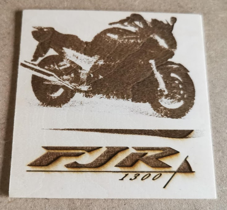
The picture below was a bold first try Although recognizable it has no detail in the picture at all. It was lasered on a Snapmaker Blank Wood Square 80x80mm (I believe that to be basswood). 1200mm/m @ 30% (the logo was 40% and is pretty deep!). Interval 0.1mm, laser is a true 5Watt.
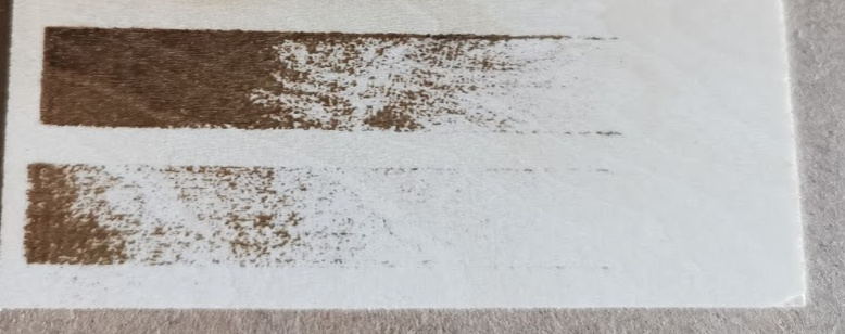
I came to my senses and made a bitmap with a fountain fill from black to white to do some testing. Because the bike was way too dark, I thought to pick up the speed to 2000 mm/m and keep power at 30%. I did a more methodical focus on black anodised alu, and upped the interval to 2mm (I expected some white lines between the black burns, but it does not look like that).
The fountain fill follows the X axis. It is a jarvis generated by Lightburn itself. The lower bar is 20% power and the upper bar is 30% I recognize 3 areas, black, white and some messy midfield, but no fountainfil. Not sure if important, but the upper bar was angeled 30 degrees.
Maybe some “standard” testing files exist, where the guru’s can see artifacts on?
Thanks!
If you’re using grayscale, you’re better off to go faster with higher power, so you’re using the full range of the PWM available. I don’t know if your board is only doing 8 bit PWM, but if it is, restricting the power to 30% is reducing the overall shading possible. Are you using grayscale or dither?
Yes it is Jarvis dither. My board is a Duet Maestro, so 32 bit. I left the S max value at 255. I see some people using max 1000 value, but since we have to set power in percentage, using high values does not make much sense.
Can you confirm that a pwm frequency of 20 KHz is sensible? I will try to ramp speed and power up tomorrow, but the strange thing is that most magnificent examples I see here, are burnt using pretty low power settings…
The 20kHz would depend on the diode used and the response time of the driver circuit. It’s sensible for a CO2, but I can’t say for certain that it is or isn’t for a diode.
I have been asking Odicforce about the meaning of the switching frequency. They state that It is common for diodes to be used with a pulse frequency of 4000 to 5000 Hz. A pulse is an off-on-off sequence. My guess is that the switching frequency is twice that. So Ive been settling with 10kHz.
Also I have been playing with the image setting, mainly gamma, and enhancement amount and radius. I do not exactly understand what it means. But I read elsewhere on the forum that values of 3 to 5 for radius and 150 to 500 for amount are quite common. It makes a lot of difference already!
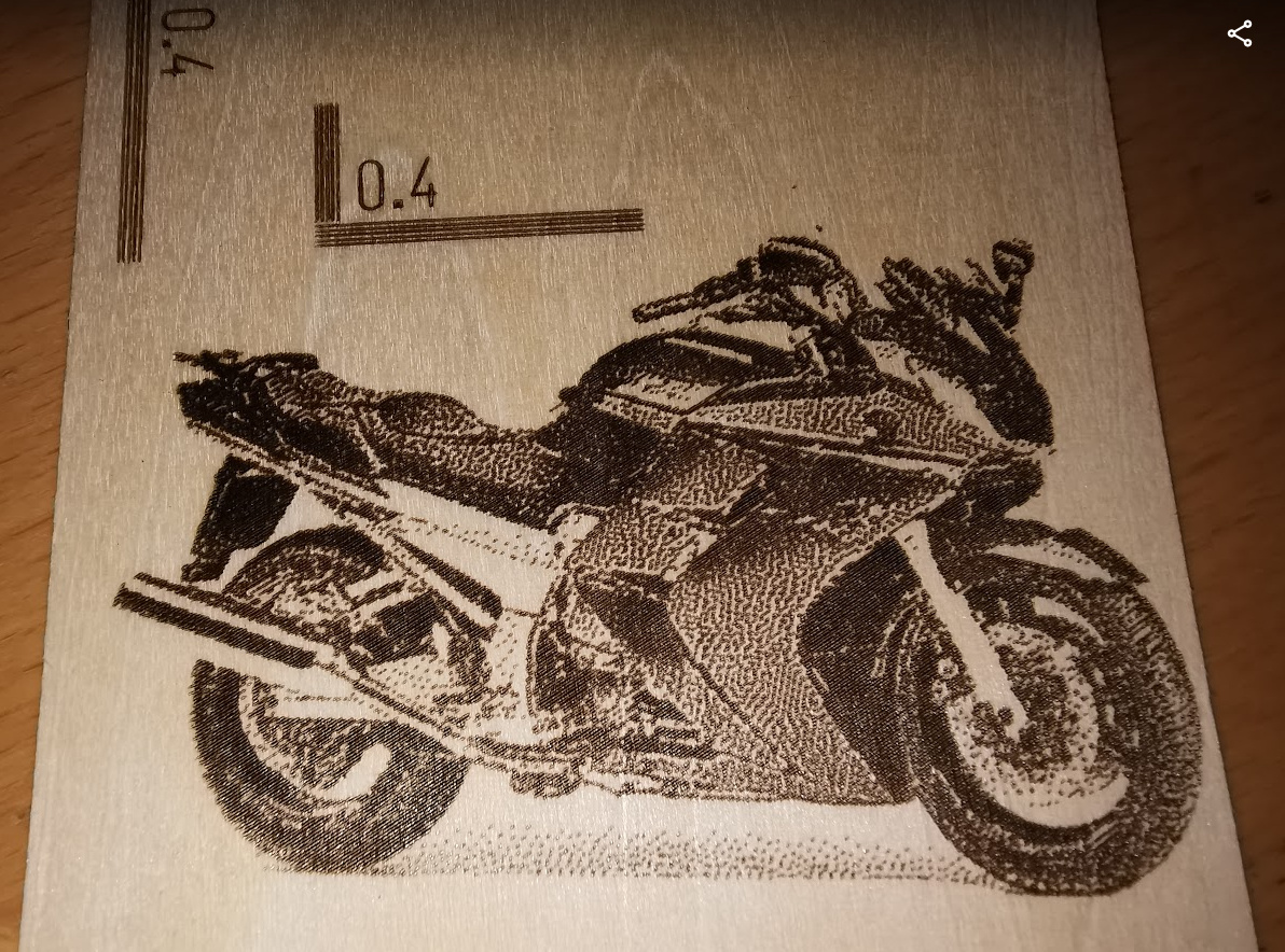
I just think the dot size should be smaller. Looks to be .2mm. The image is done at an interval of .2 and the line distance in the line test is .4mm. Black and white lines appear to be almost equal, so that counts for a line thickness of a bout .2, right?
Those lines do look thick for a diode, but without some way of knowing the scale of the image it’s hard to say for sure. You should be able to get significantly smaller than that - try using the ‘Fire’ button at the lowest usable setting, and focus on a black piece of material to the smallest dot you can make. You can also try running a ramp test to see if the focus point can be made any smaller or not.
The length of the long lines is 20mm, the shorter 90 degree lines are 10mm long.
The fire-button is no option for me, because RepRapFirmware does not fire without movement.
DC will probably be implementing an m3 variant that allows firing without movement, especially for diode users.
I have been focusing with a line of 100mm and very slow movement, on a black anodized alu surface. However the small wooden plates (Snapmaker brand) do not lay flat because they are warped. On the other hand the difference between the horizontal and vertical lines is not much. Maybe I should add some 45 degree lines, to see the varying line thickness of the rectangular diode. Or maybe there are some know good standard test files for Diode lasers? I will do a ramp test later today.
I think I will get me some thin mdf to take my experiments further. Or can you advise some other material?
 Although recognizable it has no detail in the picture at all. It was lasered on a Snapmaker Blank Wood Square 80x80mm (I believe that to be basswood). 1200mm/m @ 30% (the logo was 40% and is pretty deep!). Interval 0.1mm, laser is a true 5Watt.