Ramp mode file dimension

Hi to everybody!
I’m trying to realize rubber stamp with “Ramp Mode” enabled, but i’ve seen that when this feature is turned on, LightBurn need a lot of time to send the file to the machine.

To have a nice work i use 0.40 mm ramp with a 1700 DPI resolution (0.015 mm GAP lines).

After many tests, i’ve notice as bigger resolution correspond bigger file size. Is it correct? what have i to do to increase transfer speed?

The machine is connected with LAN cable with static IP adress

Paolo

Is your laser capable of resolving that level of resolution? You may want to run an interval test on that material to determine ideal resolution. I suspect you’re not getting anywhere close to resolution.

Short of tuning your network you’re likely already going as fast as the hardware is capable unless you have a major configuration issue. Are you experiencing other reliability or connection issues?

Does pinging the laser’s IP from your computer result in any packet loss?

Is your laser capable of resolving that level of resolution? You may want to run an interval test on that material to determine ideal resolution. I suspect you’re not getting anywhere close to resolution.

Sure, i’m doing lot of works with this setting on rubber stamp, and results are greats (as you can see in the attachment, considering the text is 2 mm height). The only problem is about data transfer speed.

Does pinging the laser’s IP from your computer result in any packet loss?

No packet lost or connection/network issues.

I’ve seen the difference also in preview mode: if i use ramp mode the file size is 9600 Kb (3 or 4 minute to send the file to the machine), but if i remove ramp mode only 300 Kb (and it sends istantly the file to the machine).

I’m not questioning if you’re getting good results or not. I’m questioning whether or not your results are actually in the level of 1700 DPI. They may be far lower either from laser limitations or material limitations. If that is the case then you’re making the file larger than necessary or desired.

Looking at your sample I’d estimate that you’re getting an actual 153 DPI. I based this with the assumption that height of letters like o, c, s are 2 mm. But if the height of the complete design is 2mm then DPI would be even less. It looks like there may be some overburning occurring which may be actually reducing the perceived DPI. You may be able to get higher perceived resolution by reducing the DPI setting in that case. Again, I encourage you to run an interval test to test for this.

Thanks, tomorrow i will try as you suggest and give you a feedback

The Ruida, in general runs a certain power as it engraves each layer. With the exception of gray scale, each scan line will run at a predetermined power setting until that object/layer is completed.

If you want a ramp, you have to continuously tell the Ruida in steps to reduce power on one side then increase power in steps on the other. Each and every change in power requires ‘code’ to tell the machine to do this. This greatly increases code size, as you noticed. You will see the same type of increase in a ‘gray scale’ image.

I would think if this was or could be implemented in the controller the size would not be much different.


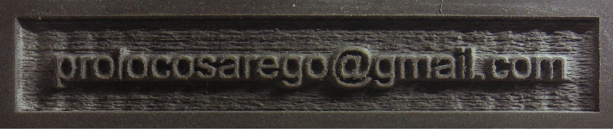
Besides the fact that your stamp will print ‘mirrored’…

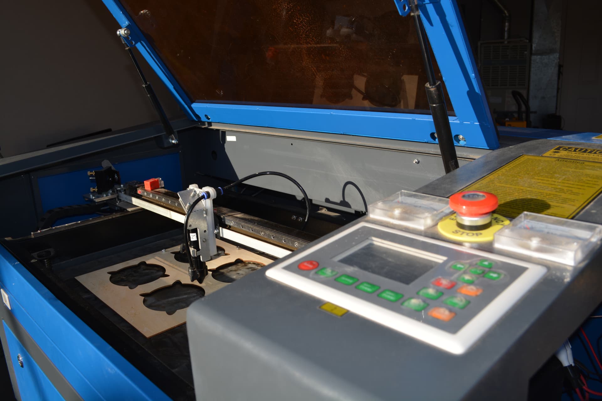
@berainlb is correct about the speeds you are attempting. I have mine pretty well tuned up and I can do about 508dpi and only with a compound lens. With all my other lenses it’s half that, around 254dpi.

Just because you ask for it, doesn’t make it so. You didn’t mention what speed you are running…


Most lps have a spec of <= 1mS response time. Meaning it can do in 1s/1000 dots. Using the 1mS value.

@ 1700 dpi running at 25.4mm/s (1 inch/s) means you have to put down in 1s/1700 dots. It would be operating 70% faster than the lps can respond.


I would also bet that the maximum speed of your Ruida is set far below that speed. It will not run faster than the limit set within the controller.

You need to keep the physical limits of the machine in mind.


This is mine, with the max set for 1750mm/s. It was originally set to 500 or 600mm/s, can’t remember exactly. My machine will run 1650mm/s because of it’s modification. I had to change the controller settings to allow the machine to use that value.

Screenshot from 2022-07-18 11-09-47

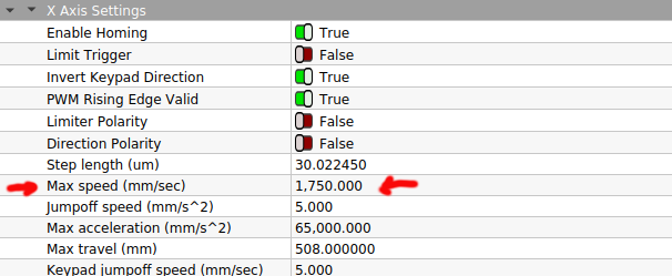
You should check yours and see what your maximum speed is and that will tell you what your maximum speed is.


Good luck

:smile_cat:

Hi guys,

i’ve checked actual settings on Ruida controller, and maybe can be done something better (watching @jkwilborn picture). Any suggestion about how and what modify?

I’m also doing some tests about bidirectional fill mode, and i’ve seen there are a diferrent position from the line starting to left and go to the right and the opposite side. So, after watching some videos on youtube i’m setting now the offset scan in machine menu.

I don’t know how fast your machine can run… that is something you have to determine. Generally for a bigger machine to run fast, it has to have more power or less mass. The other option is a large overscan.

As my speeds approach 800mm/s the overscan starts taking more space than the actual work area. So I spend more time slowing down, changing direction and accelerating back up than in the actual art. It was worse when it had the original head.

Keep the speeds down if possible.

With any mechanical parts there is back lash. There must be clearance in order to assemble and move the part. When it changes direction and the ‘other’ side slack is taken up, that’s back lash.

Not sure what you’re after…

Good luck

:smile_cat:

After some tests, first of all I have understand i had a problem with Fill Mode: after some corrections in Device settingsScanning Offset Adjust i can see a better result at different speeds (from 100 to 1000 mm/s adding 100 each step).

@berainlb you were right, i just had to use a different approach to improve engraving quality to obtain better results with less file size.

But at the same time i’ve seen a problem on change direction in fill mode as you can see in the picture below: starting from the bottom, you can see in the right side when the head change direction from right to left the end of the line is distorted, and same thing appends on the opposite side when head change from left to right.

(this appends only at slow speed, under 400 mm/s… over this value lines are perfect)

I think this also reduce my stamp quality, but i don’t have any idea how to solve this.

I suspect the head is oscillating (resonance) a little after it changes direction.

As you increase the speed the overscan probably hides it.

Is that the best focus you can get?

:smile_cat:

@jkwilborn tomorrow i’ll upload some pictures of my test.

i have seen as i increase speed, the problem decreases.

are u talking about camera focus or laser focus?

Laser… seems rather large, but it could be it’s in a photograph.

If you don’t mind, I’d like to try whatever product you are using to try this, could I have a link or name.?

:smile_cat:

Sure, i’m using a Gweike LC1390N with 150W Tube. Here there is a link to the machine:

https://www.gwklaser.com/co2/LC1390.html

Very, nice machine… Are you using autofocus or manual? If it’s autofocus, I’d double check that it’s working properly. Lines just seem ‘thick’ to me, but I could be hallucinating.


Assuming all the mechanics are ‘tight’ and there is not any slack in the head/motor transport mechanism…

Usually what causes this effect is that the lens tube acts as a pendulum and ‘swings’ when it’s accelerated and decelerated. This is usually a resonance of the ‘mechanics’. If you modify the acceleration it will usually change that effect to some extent.

This appears to me as a Y axes issue, so I’d look/debug there first. I’d suggest a radical cut in acceleration to determine if this will help. Might try 2,500 instead of the current 5,000 setting.

I think I bumped mine from about 3000 to 6000 when I removed half the mass from the gantry. Most of the work I do, usually uses the X for most of it’s work. It will slow down that axes, so it will clearly effect job time, especially if it’s vectors. This effects overscan also… but only on the modified axes.


Make sure you have a current backup copy of your controllers configuration before you modify anything. You can do this via ‘Machine Settings’ in Lightburn.

Good luck

:smile_cat:

@jkwilborn thank you!
About focus, I’m using autofocus, but i have fixed before the height of the sensor (i have also changed a 2.5" lens with a 2.0" lens).

As you can see in the picture below, nothing changed: at slow speed we can see a distorted line. When i increase speed, the problem will reduce.
I’m checking if evrithing is tight, and nothing appears loose

The only other thing I can think of is that it’s mechanical. It still looks like harmonics to me…

You really need to have speeds available below 500mm/s…

The only thing left is the ‘jump-off’ speed… Mine is smaller, 5.

Maybe some else has something else you can try.

Good luck.

:smile_cat:

There are a few things going on here, but I’ll address two.

  1. “Ramp” makes the power vary between the min and max as set in the layer parameters. If min and max are the same, you will get no ramp or slope to the edge of the letters.
    If you have minimal difference eg 10% & 14%, the ramp will be minute. I find a decent range of like 6% & 13% makes a decent slope.

  2. The wobbles on the return pass in engraving are from the ‘bounce’ due to the gantry inertia as the steppers try and accelerate the Y advance after each X pass.
    They’re clearly a dampened or shock-absorbed wobble.

I solved it by editing the Y scan acceleration low, and the speed to about 2 mm/sec - since it is only moving 0.08mm per pass, or whatever you have set it at, then a low speed is not going to be trying to force the gantry at a high oomph and immediately slow it down all inside of 0.08mm.
It is all about the Y speed & acceleration in scanning/engraving, and understanding the machine scope and practicalities - like mentioned about tiny dots at 1750mm/s being impossible to land where they belong due to the tube PSU not being able to switch fast enough to create them.

Hope this helps!

HI Jack. My understanding is Jump off speed is a cutting parameter -but it’s been so long since we tuned all the lumps and wobbles out of our big machine that I’'ve not looked lately.

Do you mind me asking how you got you high speeds- what modifications you made? Was it closed loop steppers/easy servos?

I found with out biggest machine that there was an optimal speed of around 350-450 mm/s for engraving, above which the landing and turning space needed used up the travel-speed gains, unless I upped the acceleration a lot and it would complain about possible lost steps.

Thanks for any thoughts!

The high speeds are pretty useless except for ‘fooling around’ with it. It’s very easy to outrun the lps with these things. I find myself running relatively slow, depending on the attempted dpi, higher dpi, slower speed generally speaking.


Loosing all the mass from the factory head and drag chain allows these higher acceleration rates and speeds… The real advantage is the overscan is pretty small at normal speeds.

This photo is a little old, but it’s outer appearance hasn’t changed much.

There is a section of the Ruida that is for cut operations only and there is no ‘jump off speed’ there.

It’s on each axes. My understanding is that ‘jump off speed’ is the speed it will initially move that axes and accelerate up as opposed to trying to start it 200mm/s.

At or below the ‘start speed’ will produce only ‘minimum’ power.

:smile_cat:

Thanks - good job on reducing weight, drag, and inertia.
What servos and drives are you using for both X and Y ?