My cutting surface also wasnt level. I solved it by loosening the z belt (manual) and individually adjusting the threaded rods accordingly while making sure the sprockets on the rod I was adjusting was not contacting the belt.
Yep. That’s exactly how I did mine. Loosen the belt and twiddle the jack screws (threaded rods) until it was level.
And I’ll add it’s easy because the jack screws have a 4mm pitch and the sprockets on mine have 16 teeth. So moving the sprocket one tooth relative to the belt = 1/4mm height difference.
Speaking of alignment, am I missing something or can we not adjust the height of the laser head assembly?
I just spent a decent amount of time getting mirrors 1 and 2 on the same plane as the tube (they were not) and I’m at a loss for words I can’t adjust the height of the laser head. Now I have to lower everything else the same amount and realign again. The really annoying part is the tube mounts are not adjustable, so that should be fun.
@nods I have the chiller that mentions 150w lasers, but only the single output. I just bought a 2nd 60w unit, and since the dual output chiller requires loopback if the 2nd output is unused, that leads me to believe they are just running the 2 outputs in series, and I should be able to do the same with my 2 machines. Thoughts?
And a 4x8 bed sounds terrible to align, but the thought of inserting a 4x8 sheet and tetris-ing my designs to reduce waste sounds amazing. Did you build it?
No, got a really hot deal off of OFFER UP. The guy bought it to do 3D mantel molding trim but realized the wood was being burnt and limited 3D effect used it only 3 times. So he built himself a 4’x8’ CNC and the misses said the laser is gone ASAP. Just happened to be right spot at the right time. This laser also does steel.
Check to see if there are 2 in ports and 2 out ports if not I wouldn’t try to use the one chiller for two lasers you could run the risk of low flow and end up burning out your tubes. Because my replacement parts are spendy I always error on the low risk side
Lucky you, congrats!
Both machines have water protection already, I should clarify I was not suggesting to connect the tubes in series directly, I was suggesting connecting the water ports on the machines in series.
I only have 1 outlet on my chiller, but from what I can gather even the dual outlet model (only costs a case of beer more) is running the 2 outlets in series. (It says to loop output 2 to input 2 if not being used)
I am suggesting that if the dual model is just series, I can run the machines in series myself.
But even if the dual chiller was not setup in series, it takes a while for the water temp to rise when circulating, so I would think I would be fine running them in series anyways…
All I can say is proceed with caution my 150w is working my chiller to keep temp in check.
No you probably don’t have Z adjustment on your head. I think this was one of reasons Russ started building heads IMHO…
Maybe the problem is your alignment procedure. From your comments, I think you believe you have a handle on it. Let me try to explain my point.
You cannot lower the mirrors if it’s properly set up. You have to raise/lower the ‘plane’ of all, which would include the tube.
The proper procedure is tube to mirror 1, then to m2 and ‘generally’ m3. M3 will depend on where the beam goes down and it might not be dead center of the mirror. Also keep in mind that the mirrors are 18mm in only one direction. M1 and m2 tilted at 45 deg gives you a little over 12.5mm in the x axes of the mirror. Your laser could be 9mm by then and leaves you only 1.75mm / side for play. M3 is tilted across the y axes…
If m1, m2 are correct there is nothing you can do but raise m3 or lower m1, m2, and the tube to match your head.
Think about what you are saying. If m2 is correct and the dot correlates at maximum and minimum distances, that means it is parallel in both planes. Lowering the mirror, wouldn’t change where the spot hits the head, just the mirror.
The only adjustments you have in m1 is also up and down, forward and back, it MUST stay at 45 degrees. Up and down won’t do anything that will change where the beam hits relative to the frame (and your head), different spot on mirror, but same on m2 and m3. Changing the distance from the tube to m1 won’t buy you anything either. Leaving you the only remaining option, moving it forward or back will move the spot on m2 left and right, not up and down.
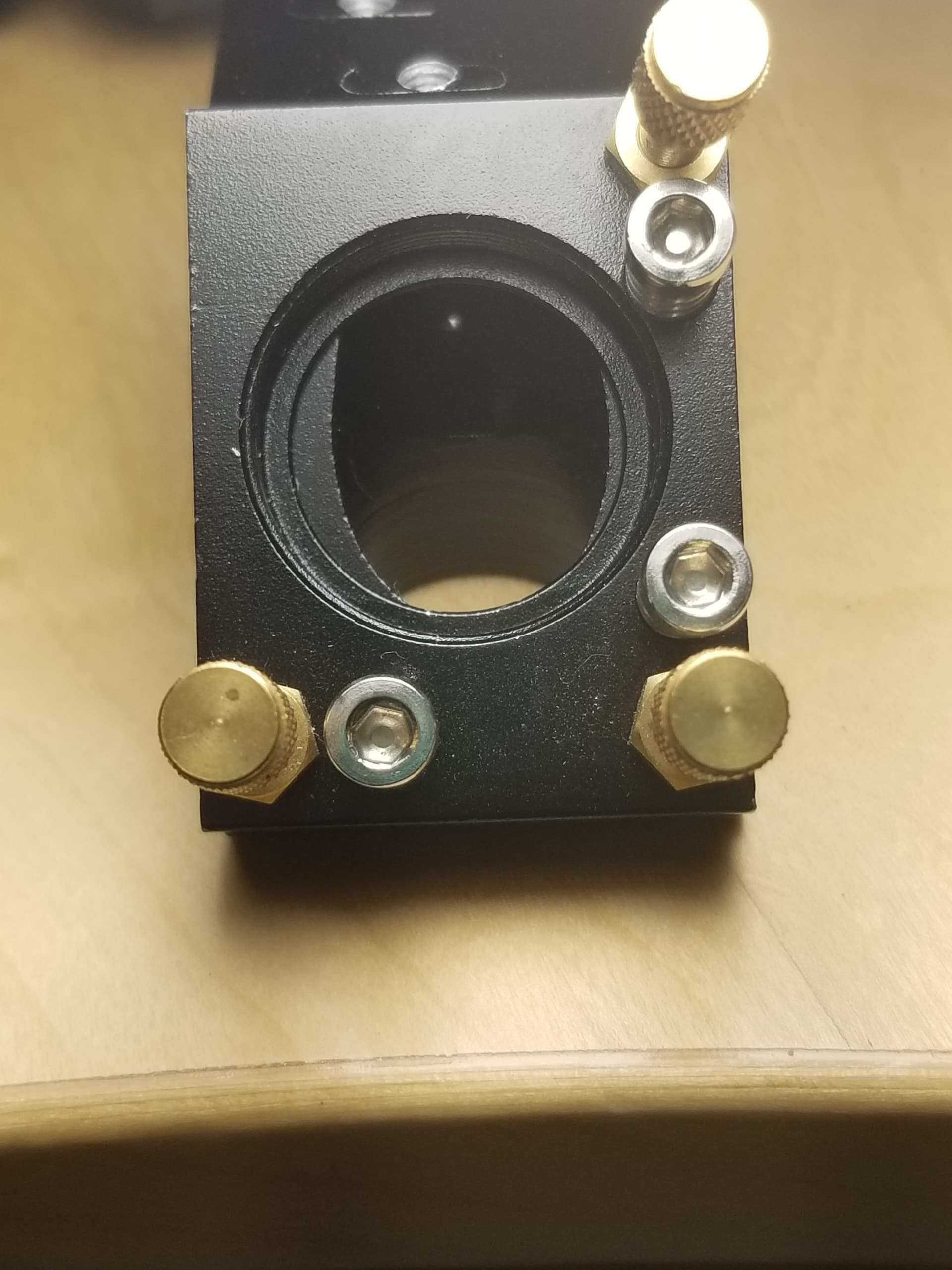
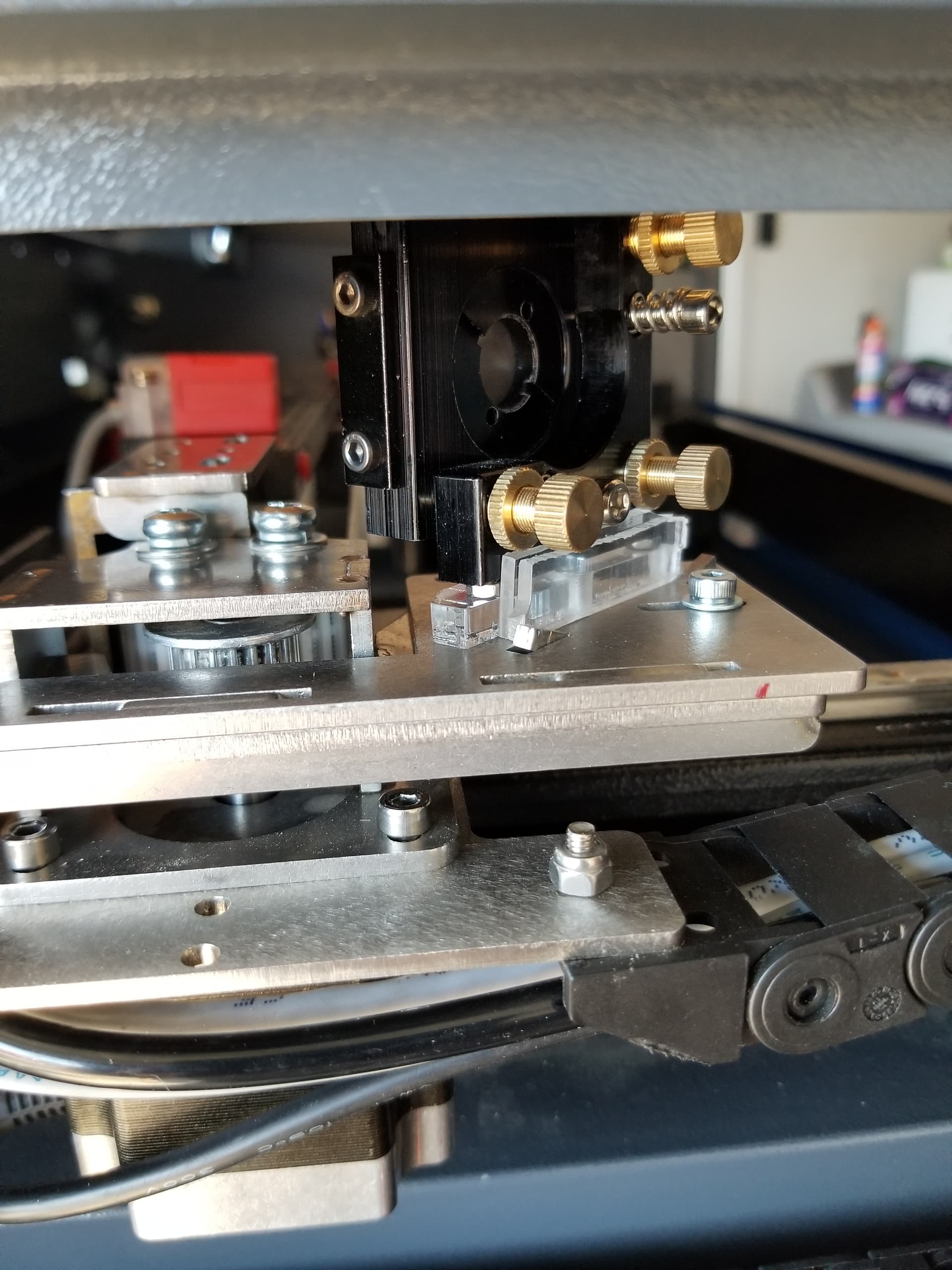
To complicate matters, here is a photo of the original head from my machine. Notice the mirror is off 1.5mm. 
This seems so simple, but the facts are that it’s a head twister. Sit and think before you duplicate what you have done to no advantage. I’ve been there, done that.
IMHO, don’t spend your money on an LED that goes the wrong direction. Might be nice on a total reassembly, but you depend on the head being correct, which is usually not the case. Also there is little chance you can align that leds beam to the tube. And when you’re done, you still need to adjust it for the beam of the tube, not the thingy jammed in the down tube.
We’ve all been through this. When you take one of these ‘really’ apart and reassemble it with different parts, the alignment procedure becomes very clear. There is time involved, don’t short circuit yourself.
I’ve found most tubes makers that state a temperature use 20 C or 68 F. I run mine at 25 degrees in the SW desert when the ambient temps are over 100. It’s a 5202, dual outputs (series).
Good luck…
The issue isn’t my procedure, it’s that this head has no height adjustment. I have been testing the beam all along. This forces me to somehow lower the tube the same amount I wanted to lower the head, and the tube mount does not have granular adjustment. I’ll drop M1 and M2 the same amount so it strikes the center of all mirrors.
So no condensation issues? Dew point must be really low?
Good call with the last mirror, I might just replace the head.
If you understand you have the lower the whole mess, not just one or two mirrors you are ahead of most people. The main reason I modified my machine was to really learn how it worked. The first failure that I ran across was the fact that there is no Z adjustment in the head and no Y adjustment on M2.
This is my m2 after a few modifications… It right on… Don’t have a current photo.
This is an earlier incarnation where I needed to move m2 4mm on the y axes.

Don’t feel alone
I took off over 700 grams of weight and replaced it with around 180. Accelleration is at 50,000 mm/s/s and max speed so far is about 1650mm/s. Now that all that mass is off the machine.
This is another older shot… No drag chain, wires, brackets or other garbage…

If you’re interested, here is a photo of the tube mount.
and the business end.

Right now it’s very humid, to us, in the desert. The dew point is 50 deg F. usually it’s anywhere below freezing to around 50 deg.

1 Like
Looks like they added Y adjustment on M2, that’s a good start. I can move M2 xyz.
I 100% agree, the knowledge gained of how this thing works is worth the learning curve required to get it running right. Bang for buck and repair/upgrade ability.
There isn’t a steep learning curve, it’s an overhang, climbing and scratching your way up ![]()
M1 can slide along the 45 deg tabs on the mount, allowing you to put the beam in the center of m1, while maintaining 45 deg. M1 is part of the tube mount, once aligned, you can slide mirror/tube mount along the x axis and move where it strikes m2, without upsetting m1 alignment with the tube. This is m2s x adjustment. M2 itself has it’s own y axis adjustment.
This is not something I would recommend to all, just someone who wishes to expend the time to learn this stuff, you don’t need a 1600mm/s + head speed as most of my stuff is around 300mm/s or less. It did make ‘overscan’ much smaller, which increases speed overall. What I always forget to mention is that it was a 500x300 machine, it’s now 511x344. I can actually do a 12x12" tile or mirror piece without a note from the Ruida complaint department.
It is fun to run 1650mm/s ![]()
Most of the parts of these Chinese machines are not top grade, so it might not be the machine for something that you need to put food on your table. But for my purposes, it has been really great. Not to mention, you can usually go to Amazon and get what you need overnight, sometimes that day…
About the learning curve…did I mention the hair on my floor ![]()
Take care
![]()
G10, polystyrene, acrylic, cardboard, packaging foam
we engrave all of the above and glass, leather, annodized aluminum, powercoat, painted, silkscreened (G10 and alum), plastic, rubber, activated marker compound
We just had to make this decision… and its not close. its 60 to 80 thousand for an “american” machine and we have total invested in the two machines we have running less than 10k including all the improvements, and there is nothing we could have bought for that that would be anywhere close to the production. Plus we have two complete independent cells. Spare parts are everywhere for chump change. With light burn we have trained a college student in our machining program from zero to autonamous in less than one month. Now that he can run all our work I am going to spend a day or so showing how to align everything.
How did you get the system to turn the laser on/off faster? when I am engraving .2 in or smaller letters when I go from 5 in/s (127mm/s) to 10 in/s (254m/s) there is a noticeable difference in the letters where they “thin out” and when I raise power to get back depth the letters are still thinner.
This brings up something that is kind of bleak to most people. I know lasers in general and the CO2 and LED models pretty well. Don’t say I know all lasers.
It was an epiphany to me to when I snapped that I have no power control over a laser, it’s an illusion created by the duty cycle.
When it lases it lases at 100%, it can’t lase at 50%… That’s not how it works. We all know this, if we think about it…
The only real control you have is speed. Does that make sense?
I missed the power response part…
Check out Russ video at about 55:10
I have a High Voltage resistor stack for my power supply that I just got the resistors for. I hope I can put my scope on it and measure the response time of the lps…
I think the default PWM freqency is 20kHz (on/off of duty cycle). I would think the 50% on/off result would be similar to a 50% current limited approach since that’s so fast, but I don’t know enough about the response time of the tube or how the PSU delivers power. I’ll watch that video when I get home. Interesting stuff…
@Maccass what was the college student’s major? I may need one of those myself soon to run my lasers.
And what did you mean by ruida complaint department? I send all my jobs over ethernet, are you running the job from lightburn directly? I have never tried that before.
Also, 8 character filenames are killing me in the ruida.
He is in cnc maching program at a technical college. He is in the apprentice program so technically he is still in school. He works here for the apprentice part and goes to school about every day. We have several of them we train some of them on different trades/machines and then let them train each other.
1 Like
check this video out for reference made by an engineer. (102) RDWorks Learning Lab 219 Lenses and Laser Beams Laugh at Lens Theory - YouTube
You can let the students train each other, but don’t let the machines train each other. They have lasers.