RepRap for laser cutters - STM32

Continuing the discussion from Duet Controller Support:

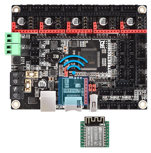
Today BigTreeTech released their new SKR2 - A new controller powered by STM32F4 @ 168Mhz supporting Marlin & RepRap firmware. Currently my K40 is running smoothierware & Cluster on a LPC 1768 @ 100Mhz and would really like to switch to a faster and up to date controller. @LightBurn Oz , I know you were really busy with 0.9.22 (Thank you - love it) so I can only hope you had the time to test out RepRap so we could enjoy faster / better / reliable engraving.

Thx.

Theres little real-world performance difference between the LPC @ 100MHz and the STM @ 168MHz that you would notice in motion control.

The problems with grbl-like firmware and lasering isn’t in the chip performance as it is in comms performance - which won’t change using the SKR2. They use the same USB/serial control.

I don’t think the performance is strictly comms related. While LightBurn strives to keep the serial buffer on the laser controller full USB/serial isn’t the bottleneck, rather the ability of the controller to empty its serial buffer, which is dependent on the firmware being able to process and execute the lines of Gcode, (and the machine being able to perform fast enough to consume those commands). That’s not to say that a faster processor would equate to a faster machine, just that I don’t think it’s a comms issue.

How does it fill its buffer? Osmosis?

It doesn’t fill its buffer, it empties it. (Like what I wrote in my post.) Specifically LightBurn fills the receive buffer on the controller and the controller empties its receive buffer by processing its content. And I don’t write the firmware so I couldn’t tell you how it does that, pretty sure it’s not osmosis though. As for the controller filling its send buffer, I doubt that happens since it’s not sending nearly as much data as it receives.

The issue with grbl-like controllers and lasering is that the buffer empties faster than it can be filled, especially noticeable when scanning using small intervals.

It stalls waiting for the next block of data to be received. A faster processor would exacerbate that effect.

This is why 8-bit/slow controllers don’t see the same issue - they aren’t processing the commands quickly enough to empty the buffer.

The controller has to indicate it’s ready to receive. Lightburn doesn’t ‘push’, the controller pulls.

This is not my understanding of how it works at all. Do you have some reference for this? I’ve read most of the official GRBL stuff and a little of the Smoothieware, but GRBL was written with 8-bit Arduinos in mind.

Actually I think part of the problem lies with the incredibly small look ahead buffer. Oz mentioned this in a post recently, (or I saw recently). Not sure how that plays in to processor and machine speed.

The controller sits waiting. It receives a command, checks it for validity, decides what to do with it (move it to the motion control stack and work on it, or return a response to a query) and indicates it’s ready for the next command

Lighburn is monitoring the serial port and sends the commands when told to by the UART

The controller, once the buffer is full, will indicate this, until it has capacity to receive more data.

If the motion is small, the motion can be processed much faster than the serial connection can be filled, resulting in the controller waiting for the next command from LightBurn.

it’s all controlled by serial UART at a level below that of both the controller microcode and LightBurn.

The receiver tests the state of the incoming signal on each clock pulse, looking for the beginning of the start bit. If the apparent start bit lasts at least one-half of the bit time, it is valid and signals the start of a new character. If not, it is considered a spurious pulse and is ignored. After waiting a further bit time, the state of the line is again sampled and the resulting level clocked into a shift register. After the required number of bit periods for the character length (5 to 8 bits, typically) have elapsed, the contents of the shift register are made available (in parallel fashion) to the receiving system. The UART will set a flag indicating new data is available, and may also generate a processor interrupt to request that the host processor transfers the received data.

Communicating UARTs have no shared timing system apart from the communication signal. Typically, UARTs resynchronize their internal clocks on each change of the data line that is not considered a spurious pulse. Obtaining timing information in this manner, they reliably receive when the transmitter is sending at a slightly different speed than it should. Simplistic UARTs do not do this; instead they resynchronize on the falling edge of the start bit only, and then read the center of each expected data bit, and this system works if the broadcast data rate is accurate enough to allow the stop bits to be sampled reliably.

It is a standard feature for a UART to store the most recent character while receiving the next. This “double buffering” gives a receiving computer an entire character transmission time to fetch a received character. Many UARTs have a small first-in, first-out (FIFO) buffer memory between the receiver shift register and the host system interface. This allows the host processor even more time to handle an interrupt from the UART and prevents loss of received data at high rates.
1 Like

You’re talking about UART level stuff. However the GRBL protocol sends an ‘ok’ acknowledgement when a line is processed signalling it’s ready for another. An alternative method, which I believe LightBurn utilizes, is to count the number of characters sent per line, and knowing how big the planning(?) buffer is when you receive an ‘ok’ back you can decide on whether to send the next line of Gcode or not. The processing of the planning buffer is dependent on two things, how fast you can process the data and whether there’s data available. If it can process faster than comms can deliver then comms is the bottleneck. If comms can deliver data faster than the processor can process it, (and in this case the mechanics can actually utilize), then comms isn’t the issue.

We might be talking about two different things here.

In the case of sending scanning laser data to a controller, comms is the bottleneck. The look-ahead is emptied before comms has a chance to refill it.

Cluster mode concatenates 8 units of ‘pixel’ data for each gcode command, effectively making the comms path 8x larger.

OK, I’ll take your word for it. Just glad I didn’t waste my time reading any of that UART crap you posted. :stuck_out_tongue:

Sorry to @Squid if we hijacked your thread. After all you’re talking about RepRap and maybe that new firmware has significant improvements over existing Gcode stuff. Osmosis perhaps?

This topic was automatically closed 30 days after the last reply. New replies are no longer allowed.