Hi all, I need some advice, I saw this rotary attachment video’s on youtube and I had some spare Nema 17’s laying around that I normally used with small drivers. Anyway I grabbed the parts needed to build the rotary, and start building it without really looking at my machine’s drivers. So normally you would just tie the nema into the y axis and there the rotary goes. After done building on the weekend I decided its time to give it a go, open the side panel and alas noticed that the drivers has the UVW instead of the A+A- B+B-, so it has the 3 phase steppers with only 3 wires and 3 phase drivers. So this is my question, Can I just buy a larger 2 phase driver and work the Y on the Ruida with the 2phase nema 17 and driver while still running the X on the 3 phase driver UVW, or do I need to buy an additional 3 phase stepper motor basically have to rebuild the entire rotary attachment with the new motor dimensions. ( So either get 2 phase driver, or rebuild rotary with 3 phase motor.) Just wondering if anyone has some insight on this please. Thank you.
I don’t know for sure, but…
Generally controllers put out the required signals and you pick the appropriate device and driver circuitry. I’m sure it’s doable, but when you wish to change back to the regular Y axis, you will have to deal with reconfiguration of the hardware.
You might look into seeing if you can use one of Ruidas Z or U axes to drive it. Have no idea if that’s possible, but the axes itself should be irrelevant. If you can configure the software…?
Got my eye on a rotary, so I’ll be watching.
Good luck 
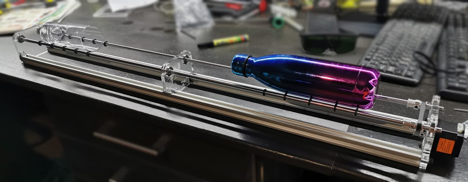
Hi Jack, I’m searching extremely deep into the googles but cannot find anything on this, info on the 3 phase steppers seems to be non existent. So I’m kind of in a 2 way street with this, do I spend money on a 2 phase driver just to find out it doesn’t work, or take the more expensive route and buy the 3 phase motor and then rip a nice rotary apart and start over. I wish I knew more about these stuff. I will update the thread as soon as I have more conclusive details or a working rotary. I will try to place an image of what it looks like currently.
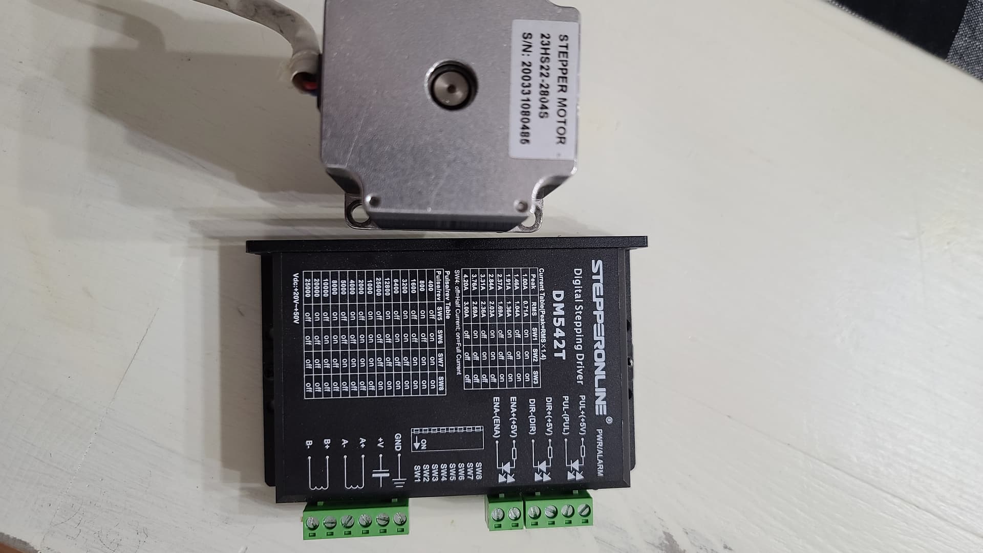
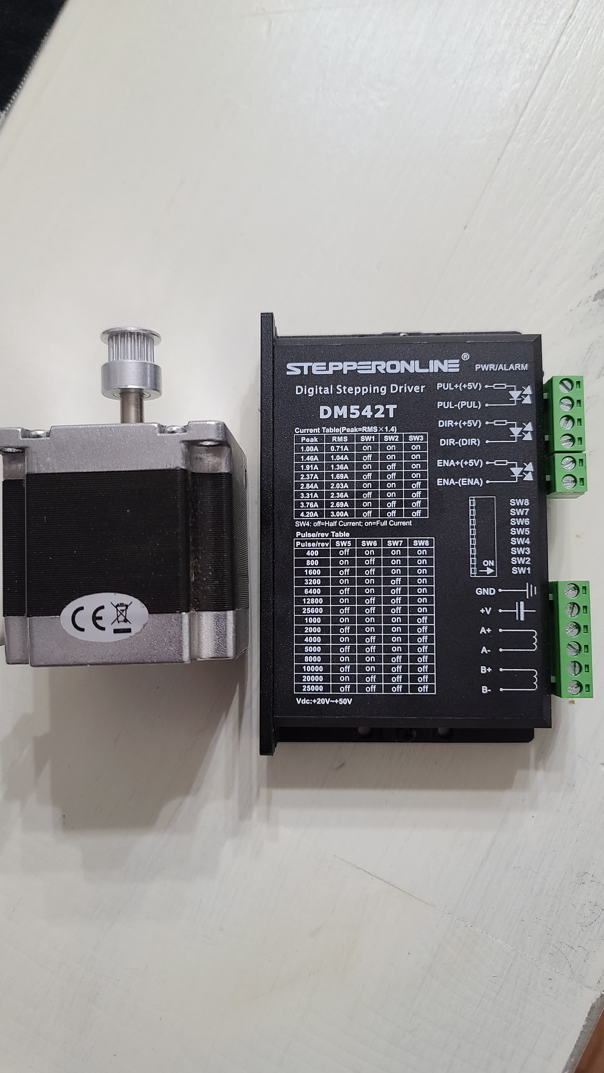
This should work for you if you are in the USA its yours it’s from a rotary unit I had. Even comes with a pulley.
Just PM me your address.
Hi Rudy, thank you, its really very generous of you to be giving the motor and driver away. If I was staying in the USA I would have grabbed the opportunity with both hands. I unfortunately am not in the USA, I live in South Africa. You definitely gave me an Idea to maybe look into getting a secondhand driver to first test it out.
You did a great job on the rotary. Might want to see how much it’d cost to ship it to you across the pond 
So the guy at the 3d printing store suggested I get a MKS TB6600 v 1.1 driver. Im absolutely pulling my hair out on this:
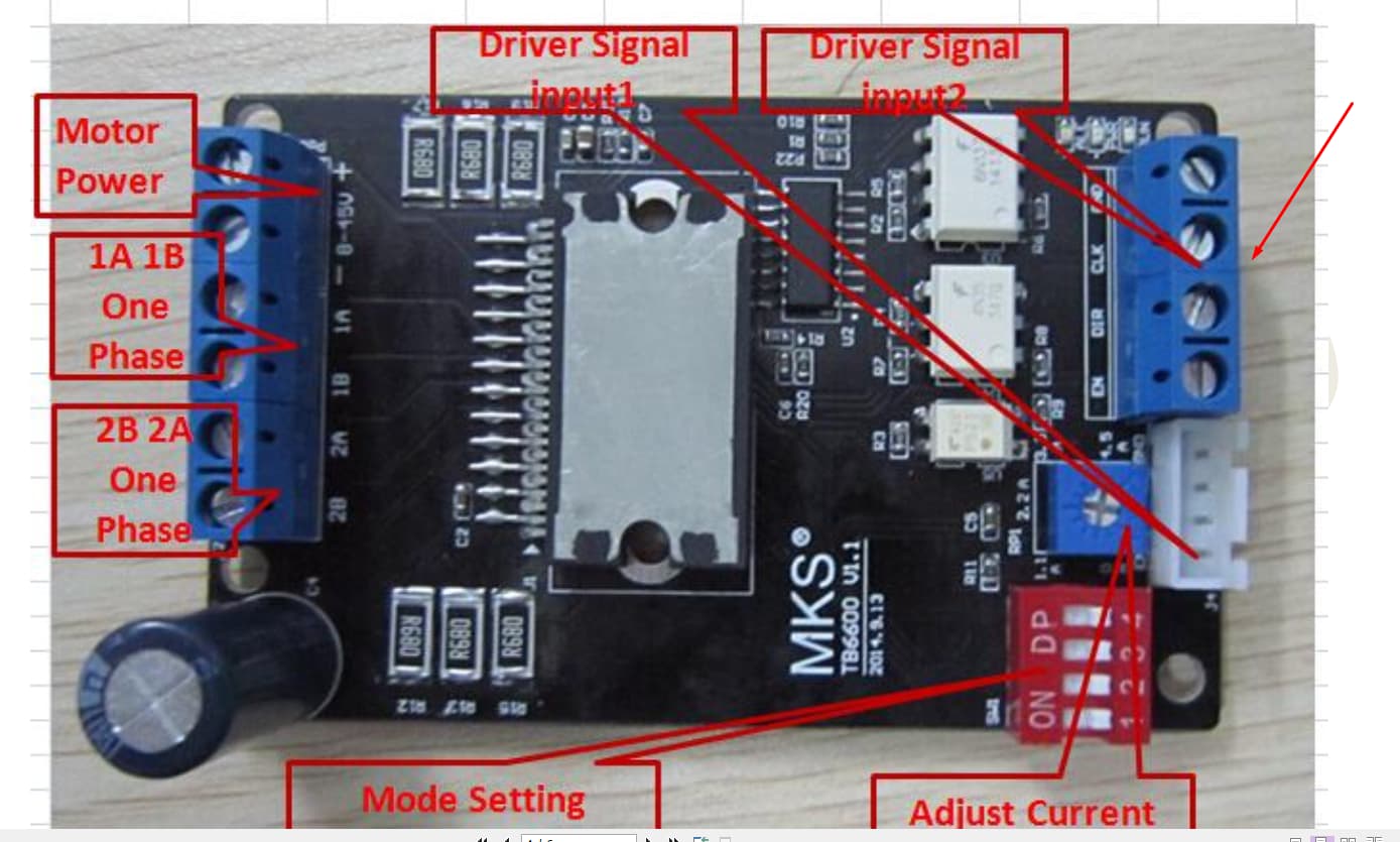

I don’t just want to connect things and blow up my Ruida. The pins are like in the picture as follows : EN, DIR, CLK, GND. How do I connect this to the Ruida Controller that has only : +5V, PUL, DIR. Does anyone have a clue how to connect this please. Everything I find on the internet has EN +, EN -, DIR +, DIR-, PUL +, PUL -.I have read every post, every wiring diagram I can find that just closely resemble this. But no conclusive solution yet, Im to worried I blow up something to start testing different setups.
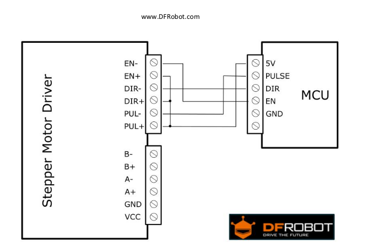
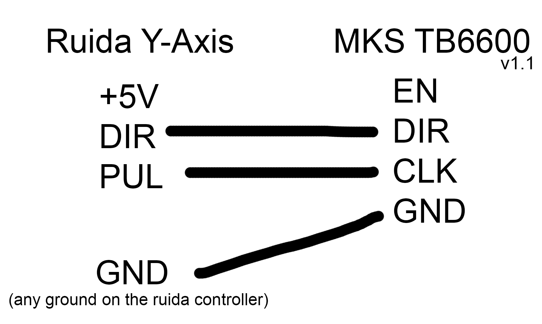
Hi All, Jack that schematic doesn’t work with this driver as explained I only have EN, DIR, CLK, GND on my driver I manage to get it working by putting GND to the GND on the controller, then putting PUL to CLK and DIR to DIR - Completely skipping the +5V. I had to connect the rotary to the Y-Axis as it doesnt work with the Z-Axis ( Lightburn did not give option to select it under rotary settings ) I kinda was prepared for this as everyone I talked to said you cannot use z or u with the rotary. Anyway after playing I started engraving on glasses etc, first engrave was without the Mirror Image on the bottle (eeeehhhh). Then the first glass I did, Cracked the glass ( double eeeehhhhh ). Third one starting to get there.


Here is an image or visual representation of the driver wiring.
I think the Power and motor connections are fairly standard on most drivers with bipolar steppers or 2phase.
Does anyone know How I can post a video on here, I would love to show it in action?
You can put it in your google drive, right click on it and select get link. On the link window, change the protection so anyone with the link can read it, then copy link.
Too much heat will crack it 
Come here and post the link…
Did you have to strap ‘EN’ up or down?

No, the EN did not have to connect to anything.
Thx for the tip on the videos.
Here is some very short clips of the rotary running:
The first video I show how I wired it up ( I still need to get everything wired to their permanent location tough.)
https://drive.google.com/file/d/1BYfO53R9uqowp-gjtuJ62GvBggFYiSFS/view?usp=sharing
https://drive.google.com/file/d/1k_0D35i6y52rvHI9o2Bw4Q_0RnEsjdsz/view?usp=sharing
https://drive.google.com/file/d/19Hu-cUxJ-_REZdLTK3YkVlDZP4KtJi_F/view?usp=sharing
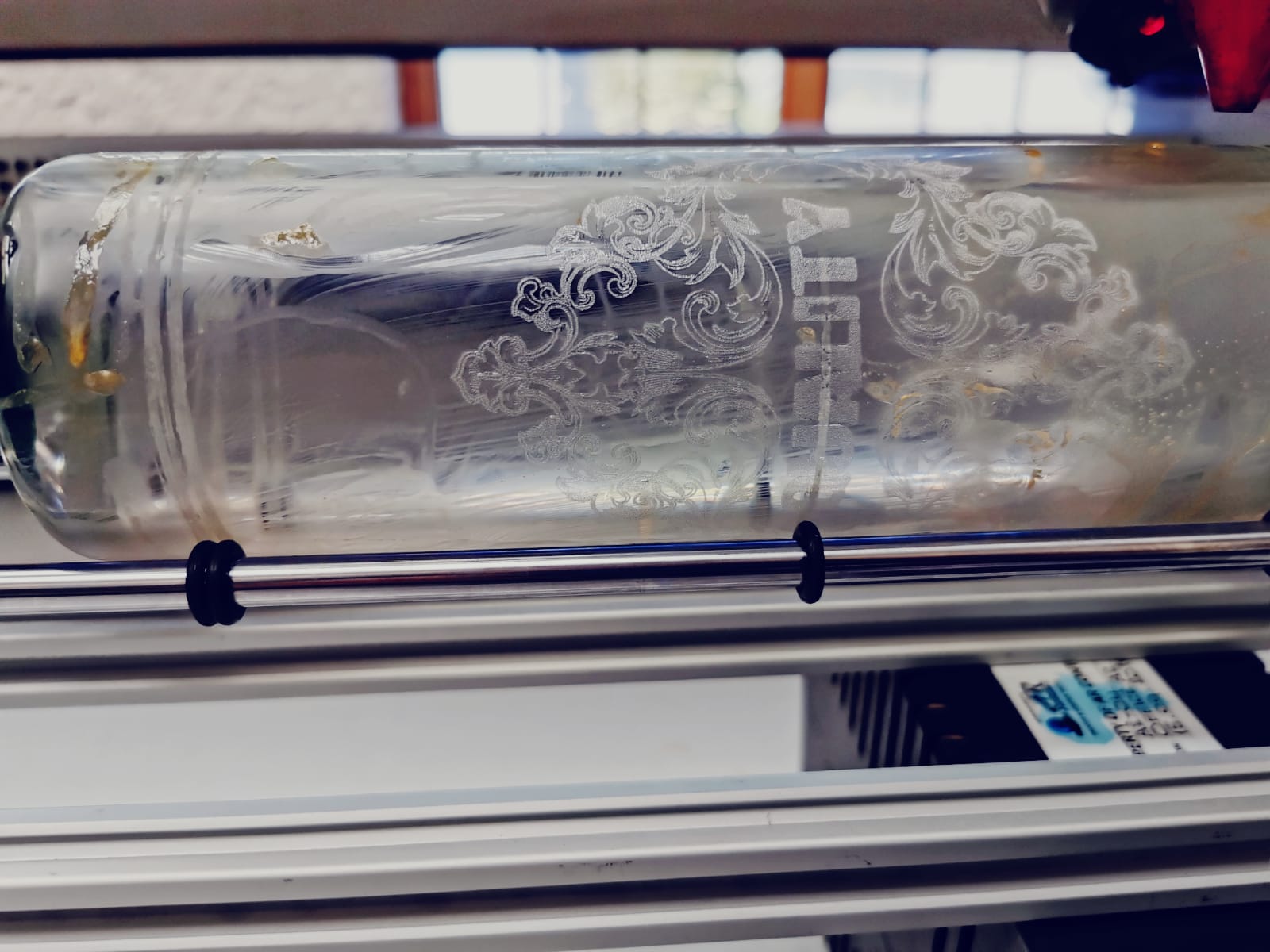
Also here is an image of the bottle busy, full of soap lol
Interesting EN was OK floating, I would have thought it had to be tied ‘active’.
Sometimes you have to ‘interpret’ these descriptions… Doesn’t seem to bother anyone they label air assist ‘wind’…
Thanks for the videos
Here something on using the U axis for the rotary.
EN does not actually float. It is pulled high in the driver. If you use EN you drive it low for enable and high for disable because the opto-isolator inverts the signal.
Thank you I will give it a go then let you know if It works as indented.
It doesn’t mention switching on the rotary in lightburn, also It doesn’t say how to configure the steps etc like I did with the software. I will play around and see if I can get it working, maybe putting those settings as vendor settings just for the U. I will update.
Normally this is what we think of when we mean ‘floating’, missing a path to ground…
Most of this stuff uses ‘sink’ operations for active. The outputs are open collector, depending on you to supply the voltage to the device to be switched (it’s floating now) and letting the controller make the connection to ground (sink.) For inputs, opto isolators are generally wired to vcc internally, just like your solenoids, and the the ‘sink’ is when ‘you’ pull it down, usually indicating active. On outputs, the Ruida sinks current, just like you must ‘sink’ current for the input. The limit switches on my machine, go low when active sinking.
Some controllers have EN+ and EN- and some just EN. If it’s a configurable controller, there’s really no reason to have hardware inverted inputs for the same detection, as software can manage it, meaning who cares if the hardware inverts it, the software can correct it…
In the end it’s all relative anyway. ![]()
Take care ![]()
This topic was automatically closed 30 days after the last reply. New replies are no longer allowed.