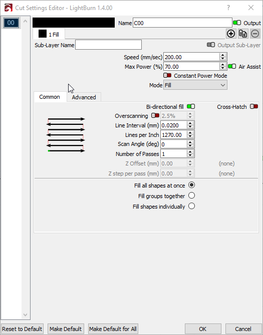
Looking for some guidance. I’ve been messing with tumbler engraving. Having jagged edges on everything. These are my speed/power/line interval settings:
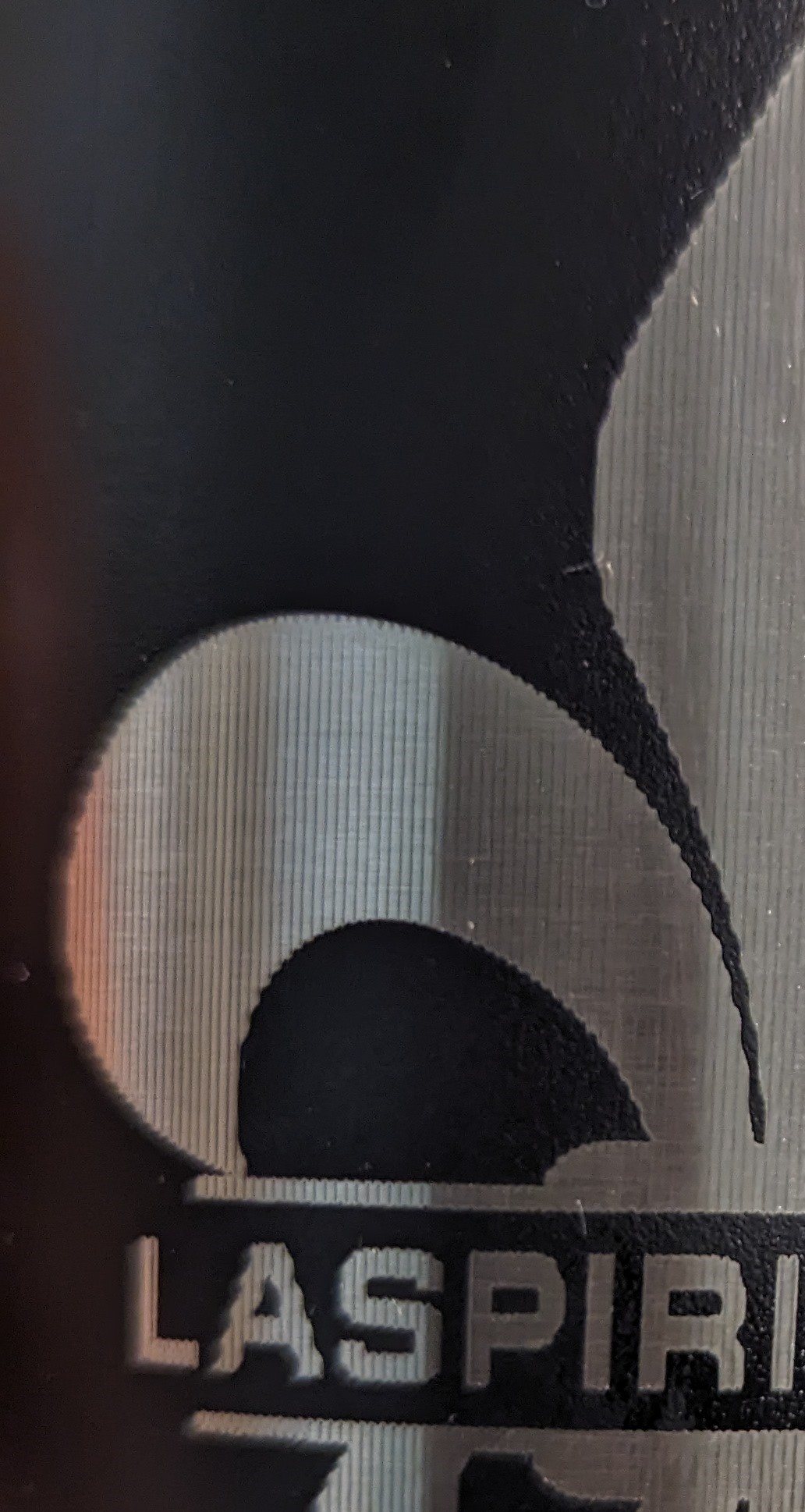
My machine is a sculpfun S30 10 watt air assist with an Ortur YRC Rotary Chuck. Quadruple checked tumbler diameter. I’ve inserted a line layer after the fill to clean up the outline but doesn’t help much. I’ve checked belts, pulleys, v rollers and seem to be OK. As you can see, my line interval is pretty small. The graphic was an Adobe Illustrator file import and the text was generated in LB. This is the effect I’m getting.
The graphic is approx 3.5" square. I’ve read about the same issue on this and other forums but nothing I’ve read/tried has helped. I’ve been chasing my tail for awhile and I’m out of ideas. Any suggestions? Thanks
Thanks for the suggestions. I’ve got a test running as we speak before I read your suggestion. I had a King Gubby Z axis adjuster on the machine. I’ve been approaching this like it was a mechanical issue to eliminate the obvious stuff. When I was fiddling with the Z axis, I noticed a little slack in the adjuster. I removed the aftermarket axis and installed the original. More rigid. I will report back with the results. If that doesn’t improve it, i will make your suggested changes and update the thread.
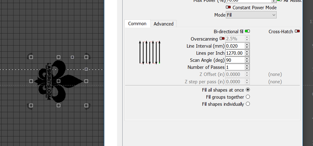
The change of the Z axis holder helped but didn’t solve it. I tried your suggestions of 90 deg scan angle and it actually was a little worse. I also tried 45 deg with the same result. I added a kerf offset on the test patterns and that helped a little as well but still noticeable. Plan to do some more tweaking tomorrow with the kerf offset and try to get it dialed in a little more. I’ll update the thread with my results.
Your are using wrong settings. You are on mm/sec. That’s not the unit for diode lasers. Change it to mm/min in the LightBurn settings.
The fastest the S30 can go is 6000mm/min, which is 100mm/sec, so you are way above the speed maximum.
For a rotary, I recommend starting with 2000 mm/min or even less. This already might lead to too high acceleration on the y axis, but check first. Use maybe 20% power as a start. If you still have the effect, reduce to 1000mm/min (16mm/s) and 10% or so.
Next, you have a line interval of 0.02. That’s also way off. The S30 Pro has about 0.08 to 0.09 mm line width (resulting in about 300 DPI).
Here are some articles to get you started with the correct settings (there are more articles that are also worth to read, but start here):
The speed units you use are up to you… 100 k/hour is the same as 61.23 miles/hour… They are both the same speed… Usually these are set you have easier numbers to deal with…
All of my machines use mm/s, because I’m used to seeing speeds in mm/s… it’s confusing to me to interchange them, so I don’t and use one the mm/s. Use whatever you are more comfortable with. I’d rather enter 25mm/s than 1500mm/m they are both the same speed.
You do need to know the physical limitations of the machine… these limits are in the controller to prevent you from damaging it.
As a general rule, you want the fastest axes doing the most work… if you scan a photo left to right on the X axes, the head is moving the most… scanning at 90 deg, the Y axes will be moving forward and back while the head moves in increments of your dpi/lpi…
With most rotaries, they do not advise rolling it back and forth… it’s not awful bad on chuck, but you’re spinning the mug around instead of moving the head quickly… If the machine is set up properly, there should be no resulting difference between the two scans, other than how much slower one will be.
I suggest your major issue is that pointed out by @misken, your dpi…
This video will explain how dpi/lpi works with good graphical diagrams… it’s on photo engraving, but the video is a must to understand how to setup the proper dpi/lpi for any laser with any material…
Fix this and lets see where you are…
Until you get the results you want, stick with the more standard way of engraving. Down the road you can fool around with things…
Thank you. What an oversight by me on machine setup!! I’ve ran 24 test patterns focusing on ellipse shapes as that is where the waves show up the most. Your suggestions improved my results. My best result is 2000mm/min 25% .08 interval fill with an outline of 500mm/min 10% power. What I’ve noticed with the lower power settings is a very slight resolution improvement, however tougher material cleanup after the burn. I’m out of test material! I’ll stock up this evening and plan to keep dialing it in. I’ll update the thread with my results.
What a cool video. This is my latest results at 2500 mm/min 35% .08 line interval. Still wavy but better. I think I will move on to line interval testing based on the info in the video you linked.
Used a line interval test per the video. Used a jewelers loupe to determine when lines were about to touch/overlap. The lines didn’t get close to touching until somewhere between .03 and .04 mm.
True Maybe, I shouldn’t call that “incorrect” but “unfavorable” setting. Of course, mm/s and mm/min are easily interchangeable, but since the diode laser community uses mm/min usually, people dealing with diode lasers get speed recommendations in mm/min in 95% of all cases. And I see many errors resulting in wrong unit conversion. And mm/min gives a diode laser 60 times higher resolution in the lower speeds, because sometimes 500 or 550 mm/min already makes a difference, which would be 8.3 or 9.1 mm/s, which is more difficult to deal with.
Some people also use a higher focus distance to enlarge the laser spot and get rid of the lines. Also worth a try while experimenting
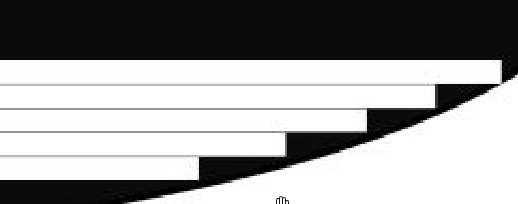
I think I have the interval settings close to where they need to be. After a few test, this illustration is what i’m seeing when the curves are magnified. This is the source of the “wave” effect.
I read somewhere about increasing focal distance to obtain a wider but smoother line. I would imagine you will lose some detail but I will try it. I set up a couple of sub layer lines, both inward and outward and that helps a little.
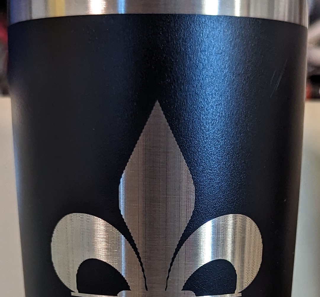
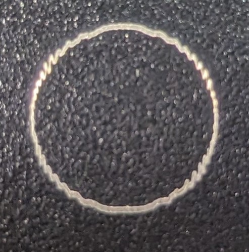
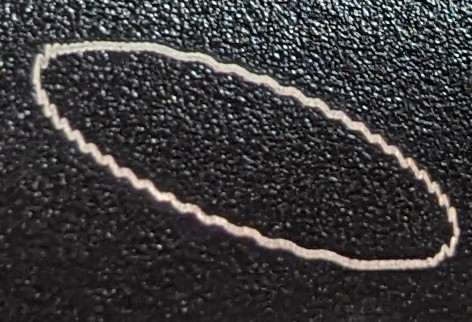
Hey guys, had some health issues for a bit but I’m back at. Still trying to solve these jagged edges. To recap, my machine is a sculpfun S30 10 watt air assist with an Ortur YRC Rotary Chuck. The attached pics are on a powder coated tumbler. I have quadruple checked tumbler dia in lightburn as well as making sure it is level. The circle is a 10mm dia. and the ellipse is 15mm at its greatest width. I have ran multiple line interval test, ramp and power test and have de-focused for a less “detailed” line. As you can see in earlier in the thread, I came to the conclusion that the jagged edges were the result of the fill starting/stopping on a radius and leaving the jagged effect. I thought about it and decided to run a test with a line only to prove this and the effect is still there on the radius edges. I’ve rechecked belt tension, eccentric wheels, tightness of chuck on rotary and seem to all be correct. As you can see, the waves almost mirror each other if you bisect the circle/ellipse. My thinking is if anything was loose, the wave effect would be inconsistent, but it appears consistent. I’m beginning to believe that it may be hardware settings that are not correct for the rotary. BTW, squares engrave perfect. The pics are oriented as they were burned in the machine. (x axis L/R, y axis Top/Bottom) Any ideas would be appreciated.
The path looks like when it turns the corner it’s oscillating in the Y axes direction. This does have the look of ringing or it vibrating as it turns the corner.
Thank you for the suggestions. I’m going to clamp the Y axis in place to test Jack’s theory and try James suggestions on the overscan. Thanks for the well wishes. Its been great having this hobby to think about. I’ll do some more testing with the suggestions and update the thread with the results.