Ruida controller not reading limit switch

Oh I’m taking it apart first!

OK I’m guessing this is an opto-protected input inside the Ruida to protect the microcontroller pins from 24V, reverse voltage, or ESD events, and, now that I think about it, an opto is about the only thing that will fail this way. The internal LED has a busted bondwire barely making contact and will flicker once as power is applied, then the bondwire kicks away from the pad and and it won’t light again. Your standard flickering busted LED.

Fortunately the opto won’t be on a microcontroller or FPGA or integrated into anything except a package with more than one opto. So, this should be replaceable.

So, BTW, on the NEW controller, this only finally worked when I switched the homing sensor on the far side of Y to the “YLimit-” input. This made no sense to me, since Y=0 would usually be on the near side and Y+ is going further away, so this should be “YLimit+”. But, it works, and the jog pad “UP” arrow moves the gantry away from me, so I’m going with that

On the other hand, this indicates to me I can still use the “broken” controller if I just use the YLimit- input, since that seems to actually do what I want. On my other machine, the YHome switch is on the far side of the machine too.

Which side of the coupler is the led on?

I’d guess it’s on the ‘other’ side of the coupler from where you can get to it… otherwise you’d have to deal with 24v across it…

Look at the controllers display and move the y axis towards the front of the machine. Is Y increasing or decreasing?

The definition of LmtX- and LmtX+, - indicates 0, + indicates max.

:smiley_cat:

Ok you’re right, y homes ok that way, y-up button moves the gantry away to rear and but numerically y is decreasing when I press y-up

I moved the switch on the rear of y to ylimit+, changed settings back and forth and right now I’m stuck in that yup button moves away from you, and y coordinate increases, both good, but homing moves gantry TOWARDS me

I found under machine config there is “y home” and I changed to “above” and back to “below” and it changes nothing with either
Dir polarity=pos
Keying direction=positive
Lmt polarity=negative I have npn normally open inductive prox sensors

Enable limit trig yes, enable reset yes pwm rising edge v no

Anything I change or sets of changes seems to just mess it up worse, what’s the magic settings? I was sure machine config y home=above should work but I flipped back and forth and it makes no difference, y tries to home towards me with either setting

If one of the axes is going the wrong way at reset you can change “Direction polarity” for that axes.

I couldn’t follow all of what you tried to tell me.

Looks like you’re ok.

I would set the ‘limit trigger’ to false. Mine are set that way and it home properly. To home requires limit switches, only servo systems know where they are at power up.

The manual is not very helpful with

“Enable limit trigger: Whether used for enabling the axis of the hard limit protection function.”

The “hard limit protection function” is only mention in the previous page, with no explanation.

At this point, we, I, may be missing something. Let do one issue at a time.

BTW, don’t use any of my numbers… I’ve got the rotary on it and most of the movements are suppressed so I don’t throw my cups around…

:smiley_cat:

I couldn’t follow all of what you tried to tell me.

I just can’t get it so Y-up button moves the gantry away, and Y increments away from you, and it will stop on the YLIMIT+ which is physically on the far side. Seems like I tried all iterations and can’t get all 3 at once. Y-up moves towards me, or decrements Y as the axis moves away, and/or isn’t homing to YLIMIT+. I thought the “Y HOME=Above” was the obvious missing piece but it seems to do nothing at all.

If one of the axes is going the wrong way at reset you can change “Direction polarity” for that axes.

If I do that, the up-arrow still increments y, but it physically moves to the front, wrong dir. My interp is it just inverts the dir at the Ruida output itself, low level. Same as swapping 2 wires on an open loop stepper or inverting dir in the external hardware stepper driver’s config.

I’m operating off the Ruida 6445 panel, I feel we need to see that work first before bringing LB’s interface layer.

I would set the ‘limit trigger’ to false. Mine are set that way and it home properly. To home requires limit switches, only servo systems know where they are at power up

So, we don’t know what hard limit is? I think it’s saying it’s not for homing, but an emergency stop. Like I might home with LIMITX-, but still include a LIMITX+ switch that should only be hit if something is horribly wrong and it’s crashing the axis and we need to abort the job. But it’s not individal LIMIT+/-, is it? Maybe it means the LIMIT input that is NOT for homing should be an emergency abort thing?

Actually a limit switch is in ‘theory’ an emergency stop. That is old technology, today most use them for initial location, or where absolute 0, 0 is.

Don’t think anyone puts a switch behind a switch in case the first one fails. Not to mention you have now made the machine size smaller. The Ruida won’t recognize one of the switches while moving, but most grbl boards generate an error if it happens. It being Chinese, maybe you can parallel them?.. I will pull one low and see what happens next time I think about it. It mus have some use I’m unaware of. In my machine they are not true and it homes properly.

I’m not sure what the end product here is. Are you trying to operate in a specific quadrant?

Theoretically you should be able to home in any corner for any quadrant. However I’ve read about lots of people pulling their hair out doing this. What you need is someone that’s done this and can give you better information on what must be modified.

This comes up so much, I’ve looked into buying a Ruida for my desk and the CNC3018 I have.

It has hall limits on both ends of all axes, which would make it a great test bed. It would also make it easy to switch each hall to Lmt - or + inputs. It would also cost me about 350 bucks… :frowning:

Currently trying to setup my lps for my tubes current limit. :slight_smile:

Take care.

:smiley_cat:

Yeah literal “Limit” switches are not that common. The homing quadrant will probably not have a limit switch past it, although it can. The opposing quadrant might, like VERY close to the stops to avoid losing travel capability.

My prob is weirdly I can’t get the Ruida configured into the most basic config for the Y: Y increments higher as it moves away, Y-UP arrow on the panel makes it move away, and during homing it seeks in the Y+ direction (away) until it trips the YLIMIT+ input. The X axis configured fine, Y keeps wanting to home downwards to the front of the machine, that’s not the direction normally used and creates issues

8 days ago you stated it’s homing properly with a different controller. Is this correct?

If so, did you write that controllers configuration to the controller that isn’t working?

Get the axes working, you can change the keypad key direction.

:smiley_cat:

OK, first Ruida I installed had a bad input on YLIMIT+, it couldn’t read it, I didn’t know I was wasting my time trying to fix it by configuration.
The second Ruida 6445G has a working input. I finally got it to home, however, it weirdly only worked when I took the Y home sensor, located on the far side, and plugged it into YLIMIT-. Then you asked “is Y increasing or decreasing?”

And it was decreasing moving further away, so I see I had it ALL flipped around. It was using YLIMIT- because it was trying to home to the front of the machine (unusual and not suitable for me), but also the motor direction and keypad got flipped in a way where the features seem to work because there’s two things set wrong on each one. e.g. the keypad is inverted, but then the motor direction is also inverted, so YUP still makes it go away from you as desired, but Y decrements showing it’s actually not correct.

You’d think “OK just move to YLIMIT+ and fix the dir polarity and keying direction ya big dummy” but I couldn’t get it going the right direction and homing on YLIMIT+ and the YUP moving away and incrementing Y.

And, like, there’s only 4 iterations there, right? Seems like nothing worked. Then I found “Machine Config”-> “Y home” and tried “above”. Which, well, seems to literally promise it’s going to change the homing direction. But it’s weird that it’s not in the Y axis config, nor did I see an equivalent for changing “X home”- which is weird, because it’s totally valid for someone to want to put the x home switch on the right and home that direction.

My interp was:
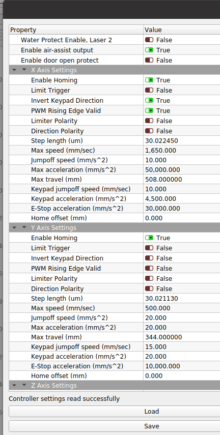
“dir polarity” just flat out inverts the direction at the pin. It doesn’t know if that means up or down, it’s just inverting it.
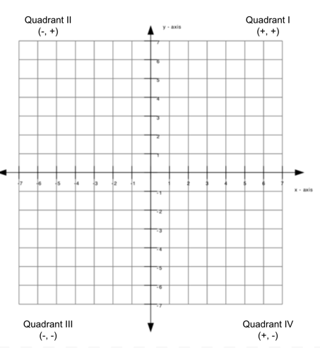
“keying direction” changed whether YUP key makes the Y axis increment or decrement, which would also change the direction the gantry goes. We want YUP to increment Y and make the gantry go away from you.
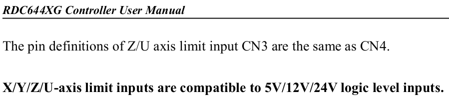
“Lmt polarity” would be whether it considers a “tripped” to be on a high or low level at the pin. We have common NPN NO inductive prox switches, it pulls low when tripped. And I’m very sure that the switch is correct.
“Machine Config->Y Home”, “above” should home by going Y+ and look for YLIMIY+ to trip, “below” would go Y- and look for YLIMIT- pin to trip.

But something’s not right. I tried this for a long time and it’s just crazy I can’t get this to work.

Mine homes to the left rear, and all of my hall limits are connected via the - input of that axes. I am in the 4th quadrant.

Of course it does. It just reverses the motors. How else could you reverse the home direction?

Clarify these three for me :slight_smile:

Of the 4 corners, where do you want it to home?
If x goes to the right, do you want to increase x?
If y goes away from you, do you want to increase y?

The LmtY+ tells the controller it’s at Y max when it’s active.
The LmtY- tells the controller it’s at it’s Y min when active.

There are 4 corners, if you stick with + that’s four options but you can also do - (as in LmtY-) which is 4 more options.

Each axes can have + or - for the signal, so X axes can use LmtX - while the Y axes uses LmtY+. I think this doubles that number… maybe 16 never bothered to count them…

:smiley_cat:

I want X to increase going tight

Y should increase going away from you

So the origin is bottom left, numerically.

The homing switches are left and top. The homing position is not the origin.

Mine homes to the left rear, and all of my hall limits are connected via the - input of that axes. I am in the 2nd quadrant.

Wait, are you using it where y=0 at the far side and y increases as you bring it closer??
Otherwise, why would it use YLIMIT-? The switch will be the most Y+ point

Just so we are talking the same language. I’ve hosed this up before and I’ve probably made it more difficult because of it. I learned the coordinate system with it going clockwise. In reality they go counterclockwise. I apologize for the screw up and have slapped myself a few times.

From all the information gleamed so far the Ruida can only deal with home being at the 0, 0 location and this is determined on where your homing switches are located.

‘Home’ on the graph is always 0, 0 so we can determine quadrants more easily.

I operate with home (0, 0) in the 4th quadrant. The only place you can have it home for the 4th quadrant is back/left. Third quadrant, back/right… First quadrant, front/left.

Whatever quadrant you are in is your machines available work area. Everything else, including negative numbers is ‘out of bounds’.

Being at 0, the only direction is an increase. Assuming a 4th quadrant home limits in the back Y and the left, X.

Using LmtY- (and X) means I’m at 0, 0. The only Y movement available is an increase and will have to be towards the user. X increases to the right.

Homing in quadrant I, again I’m at 0, 0. The only Y movement available is an increase and will have to be AWAY from the user with X increasing to the right.

Make sense?

:smiley_cat:

Interesting Jack and explained perfectly.

Well, I know the theory…

Too bad you can’t just move the wires… There are apparently other settings that I am not aware of if you just change the wiring. I’ve tried to play around with mine, but so far it ignores the + inputs.

Many moons ago I though I saw something about it, but have no clue where it was… lost in the ‘cloud’ I guess…

@Stroonzo has a lot of knowledge on these controllers, much more than I. He had some configuration stuff that he had to access via RDWorks, if I remember correctly about setting these up.
I’d also like to know where/what the ‘trigger limit’ does. The manual is far from clear.

I was hoping he’d stop by with an epiphany for us. It doesn’t help that I don’t read/write/speak Chinese. :frowning:

:smiley_cat:

I was expecting to operate in Quadrant I (+,+). Overall, homing does not “need” to go to the origin, it can home to the far side and then set the current coordinate at that point to be the “breadth” parameter. ULS machines work this way, homing at the far right while 0,0 is near left, and parking at the far right after homing and any time it is idle. The most natural coordinates to work in is quadrant I, (+,+), but physically moving the gantry to the front of the machine is inconvenient as the gantry is in the way of loading stock at that point.

So are you saying this is simply not possible with the Ruida 6445 itself (without bringing in Lightburn’s config layer), you can’t use a homing switch at the far breadth location for that axis, it must be at the coordinate system’s 0 for that axis? Or at least, if it is, no one has found out how?

Is there ANY capacity in the RD6445 to assign an offset between the axis homing switch and 0? A homing switch need not be at 0. I know, like, LinuxCNC lets you mount the homing switches with mediocre accuracy and you can adjust it so “when you find the homing switch and complete the cycle, that is X=5.2mm” There is a physical end stop at X= -2mm but there’s no room to mount the homing switch and the static metal end stop can interfere with the inductive prox sensor sensing the carriage as is passes.

Hmm actually now I’m wondering, could it actually be using “LIMIT-” as homing switch regardless of home being in the + or - direction, and the LIMIT+ might be for an actual “LIMIT” e-stop that was never even implemented? I can’t entirely rule that out, the names aren’t even right.

This is a PITA to test because if the machine skips over the switch during the homing cycle, it slow-crashes on a stop which is detected by the closed-loop stepper drives resulting in a fault state that disables the drive, which can only be resolved by cycling power. Which means powering off, physically grabbing the gantry by hand to move away from stop (so it doesn’t immediately repeat itself trying to home on powerup), power up, Stop during homing, and reentering the “RD8888” code.

When I ‘rewired’ mine, it would stutter, like the stepper timing or rate was wrong. Put the limit back on the - input, it worked fine. So changing a simple input, caused major issues just in the motor driver system.

With it on the + terminal, I set the home speed slow and triggered the hall with a screwdriver. The light would indicate it’s operating, but the Ruida ignored it and continued on. I could then escape out before any crashing.

I’m sure there is something about these controllers that I’m unaware of in the configuration as I’ve seen them homing on all four corners.

There is also the ‘limit trigger’, I can find nothing to indicate what its use is.

You may be exactly right, I think we don’t have enough information yet to get anywhere… I would not be surprised if it is possible.

I believe that is in the X and Y axis there is an offset you can use, never have used it, but I’ve see it.

I don’t know that for sure with these controllers. I have much to learn, but I’ve seen them in many configurations. I’m relaying how I was taught this decades ago. CNC is the same game, doubt it will change.

This seemed to work ok on the grbl boards that I’ve had. My little machine has limits at both ends of X and Y, and a single hall for the Z, but it will trigger at either limit. Didn’t fiddle much with the z axes, but did a lot with the X and Y configuration wise.

:smiley_cat:

So am I correct in concluding no one knows for sure how all the stuff in Ruida actually works?? I mean, that and WTF is “Y homing above/below”?

No biggie I think I’m seeing it’s not because I’m not explaining myself well enough here. I don’t see where anyone knows all of how this works, only that they got something working.

There are many questions about how some of this works. Most of the issues, IMHO are the translations are all we have. One of the reasons that Russ gives for starting the RDWorks learning lab is the program RDWorks is very confusing and many of the settings of the controller are equally as incomprehensible. Haven’t made it through his whole video collection.

I believe @Stroonzo know much more about this and was hoping he’d at least give us an opinion.

I realized I hadn’t checked a couple places yet, that slipped my mine.

About a year or more ago, I started looking at these and found a pdf on how to set them up from scratch. Read a few things in it and moved on. Later an ‘oops’ wiped the disk and the backup turned out to be corrupt.

I lost it and have never been able to find it again. Just explains why you always make 2 backups on different media at different locations.

So someone out there knows…

I haven’t seen this, where is it?

:smiley_cat: