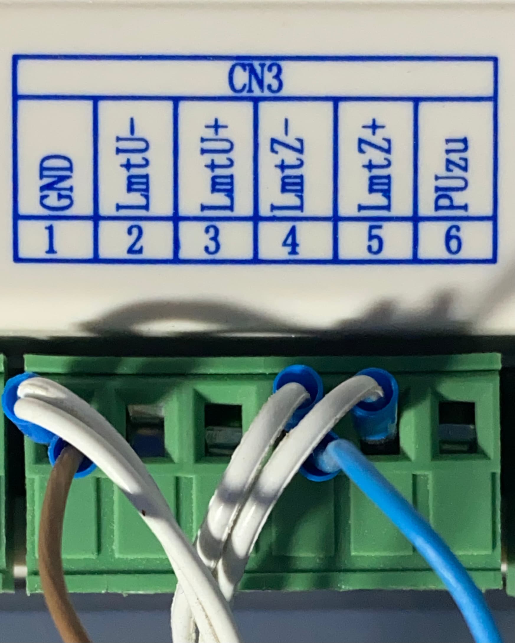
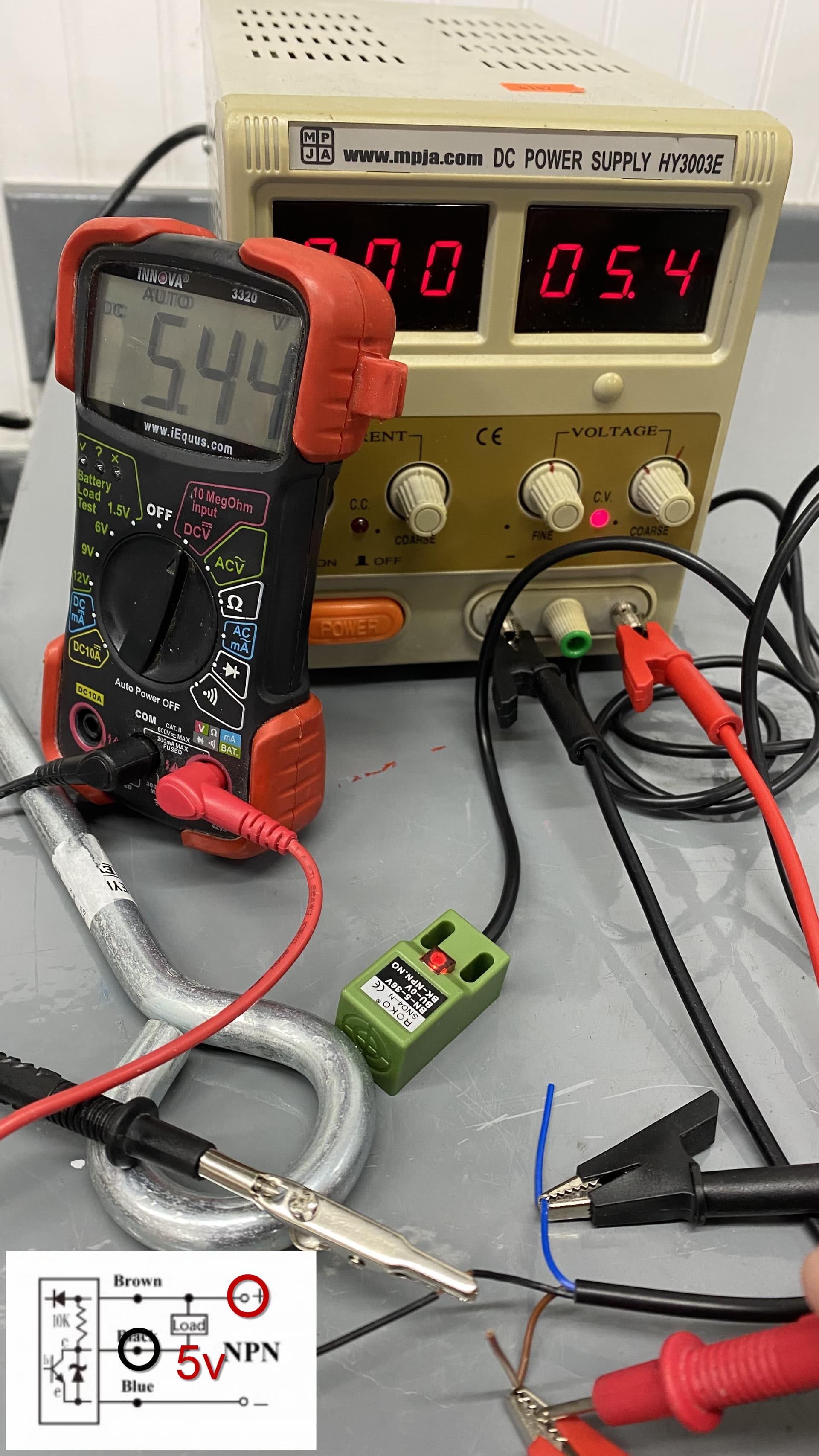
I’ve got a RDC6445G here and a 24V NPN inductive prox switch, green SN04-N. It has an LED that lights on cue.
This channel isn’t reading on the Ruida, as shown on the Diagnostics panel. It’s definitely configured as active-low. I went back and physically measured the voltage on the Ruida terminal and it’s 0v. I’m aware of the confusion of the prox sensor’s “brown, blue, black” convention, but since I measured the voltage I think I’ve got that.
I tried redoing settings a number of ways, and for a short time I DID see the indicator on Diagnostics on on and off when triggering the sensor. But after a reset it didn’t, and I couldn’t recreate it.
I do note that the sensor, although an NPN, did pull up the Ruida pin to 24v when open, so there’s some sort of leakage there. The pins are driven by Ruida at ~4v if left floating with nothing on them. Is the pin able to take this sensor directly if it raises the voltage to 24v? That’s a very common sensor and all the instructions I saw were to wire it straight into the Ruida. Also saw 24v on other limit switch pins that were working fine. I don’t think the problem limit switch channel is physically dead, I swear I saw it respond for a bit. Am I missing some nuance of connecting? I do have its 24v and ground on a busbar shared by Ruida’s 24v supply. But the limit switch’s plug shouldn’t have an isolated ground here.
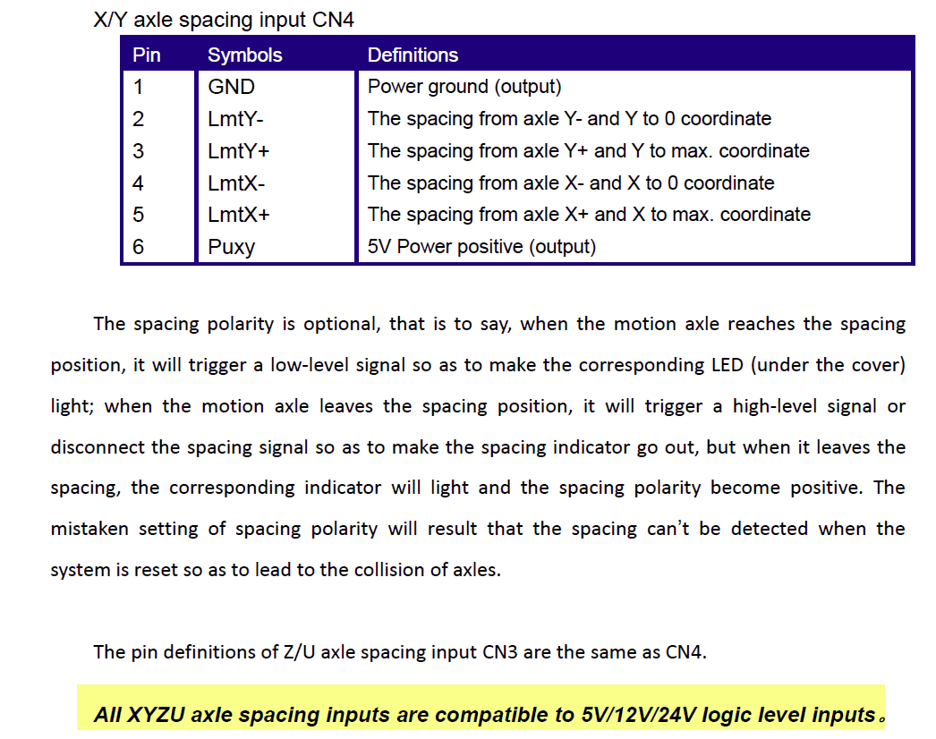
OK, but wait… PUzu is only a 5V supply from the RuiDa. Most prox sensors are commonly 6V-36VDC, but yours seems to be saying 10V-30VDC? It’s still working when only supplied with 5V?
I’ve noted that while they say “NPN” switch, the inductive prox sensors are not quite that. A true NPN while “off” would not read any voltage unless voltage is applied externally, much like a mechanical switch. The true NPN open collector could pull down any voltage the controller has a pullup for.
But the inductive sensors, once powered, they’re outputting 24V. It shouldn’t be a strong drive, and the RuiDa isn’t clamping it either.
The manual does say “All XYZU axle spacing inputs are compatible to 5V/12V/24V logic level inputs” so, yes, it should tolerate 24v as the inactive and trip on ~0v as active. I think I’ve met all the specs here.
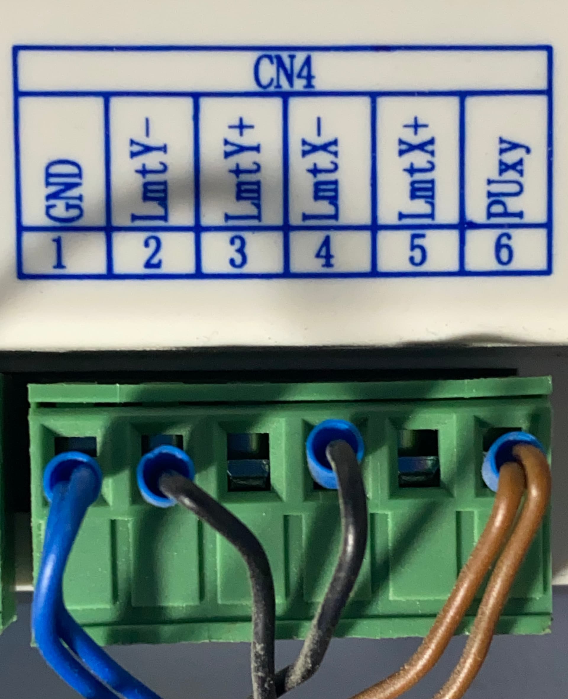
Aren’t these standard NPN sinking switches? That is, when the base is sourced (in this case the base is sourced by detecting metal), the emitter / collector is closed, the controller sees a closed contact from LmtX / LmtY to ground.
Blue Wire = Emitter (on ruida connected to GND)
Black Wire = Collector (on Ruida connected to LmtX/ Y/ Z aka the load)
It does use an npn pulldown but this, like some other prox sensors I’ve used, has some sort of internal pull-up resistor to the 24v supply. I don’t know why but it drops to 0v when tripped so ok, as long as the ruida input can tolerate 24v when untripped
Ok here’s the weird part. I’m at the machine, but not using the prox sensor at all. I’m manually grounding the ylimit+ input. The doesn’t make the ylimit+ button on the diagnostics panel light, BUT… I just noticed it makes that diagnostics panel flicker every time I touch it. What gives?
Led #4 on the ruida lights up when I ground the ylimit+ ruida input. The diagnostics panel still only flickers the whole display (not the red indicator on screen though) So the hardware input is just fine, but the config is somehow confused even at the diagnostics panel which should be low-level
Oh crap. I just had a thought. Since this is a bulky 1610 machine, the panel cable won’t reach and I extended the ruida cable a few feet. What if it’s got data integrity probs? And their cable protocol weirdly consistently craps on this bit every time and not others?
Happen to have an unmodified original ruida cable here to. Same prob- diagnostics screen flickers like a screen redraw when the input is grounded but no actual indicator on the diagnostics panel.
Display panel says rdc-v15.01.10, so I think it’s most recent.
I pulled out the panel for the second RuiDa and plugged it in. It didn’t throw any compatibility complaints and shows same version rdc-v15.01.10. But the same prob- triggering Y+ just makes the Diagnostics display redraw, but always indicates YLIMIT+ as “off” even though the LED4 sees it’s on.
I’m concluding this RuiDa RDC6445G here is just defective. Does that ever happen?? I’m still baffled how it could light the LED but only redraw the Diagnostics panel. Like the LED is driven by a working comparator that buffers the input correctly but somehow the stage is only capacitively coupled to the MCU/FPGA input pin and can only create a transient response when pulled low, it triggers a redraw on the Diagnostics panel but changed back too fast to indicate “red” on that panel.
Do the status lights on the controller reflect they are operating or not? Those are your best visual, probably better than a voltmeter.
It’s questionable that it has an intermittent or sounds like it has one, which has to be fixed before you continue any diagnostics.
If you have to, move the keypad the ‘standard’ distance, (remove the extension) to see if that will fix the issue.
Can’t look at an led and tell how fast it’s toggling.
I had to move my x axis limit, so chased it down.
I run my hall effect limit switches on 5v, the input/output of it will handle the placarded voltages. Since the inputs of the Ruida were designed for either mechanical or electrical limit switches, the Ruida will pull those inputs high and wait for you to pull them active (low.)
The 5v runs the electronics on my switches, and it just completes the path to ground when active.
This read correctly when changing to another rd6445. And can be configured to home now. So the controller could somehow light the LED but couldn’t actually read the pin
It’s just an indicator, there is more electronics after the led, but it’s better than a guess to where the problem is.
Good luck, take care… What are you going to do with the old controller? I’m in Arizona are you in the US? I would love to take it apart, it’s probably not fixable, but you never know. It’d be good education material for the right person.