What are the results on aluminum if you run the job from this topic? Are you saying you don’t have an offset in that scenario?
The offset is corrected using the list above
That’s actually not what I’m asking. I’m asking what happens if you burn the current problem project onto aluminum?
Uhh, I haven’t tested that yet, I’ll do it tomorrow
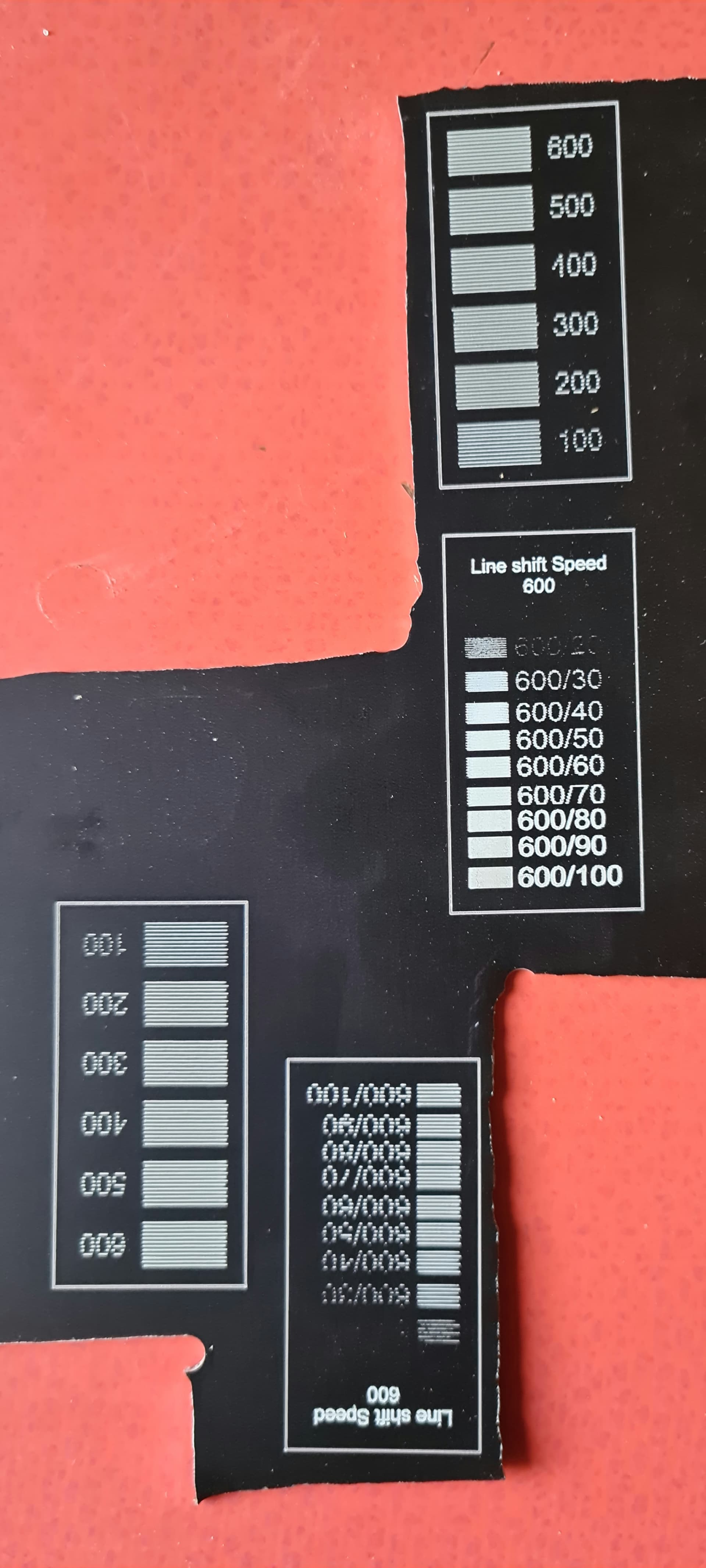
Many of the same artifacts are apparent here as well.
The results are interesting. It’s not entirely clear to me if all the results can be explained from an offset issue and overburning. However, the tight line interval is making it a bit harder to see.
Can you increase the line interval so that there’s clear separation between lines and rerun? I want to confirm with certainly if the 80-100% power level burns show an offset or not.
Now I’m just even more confused. I did all of these tests today
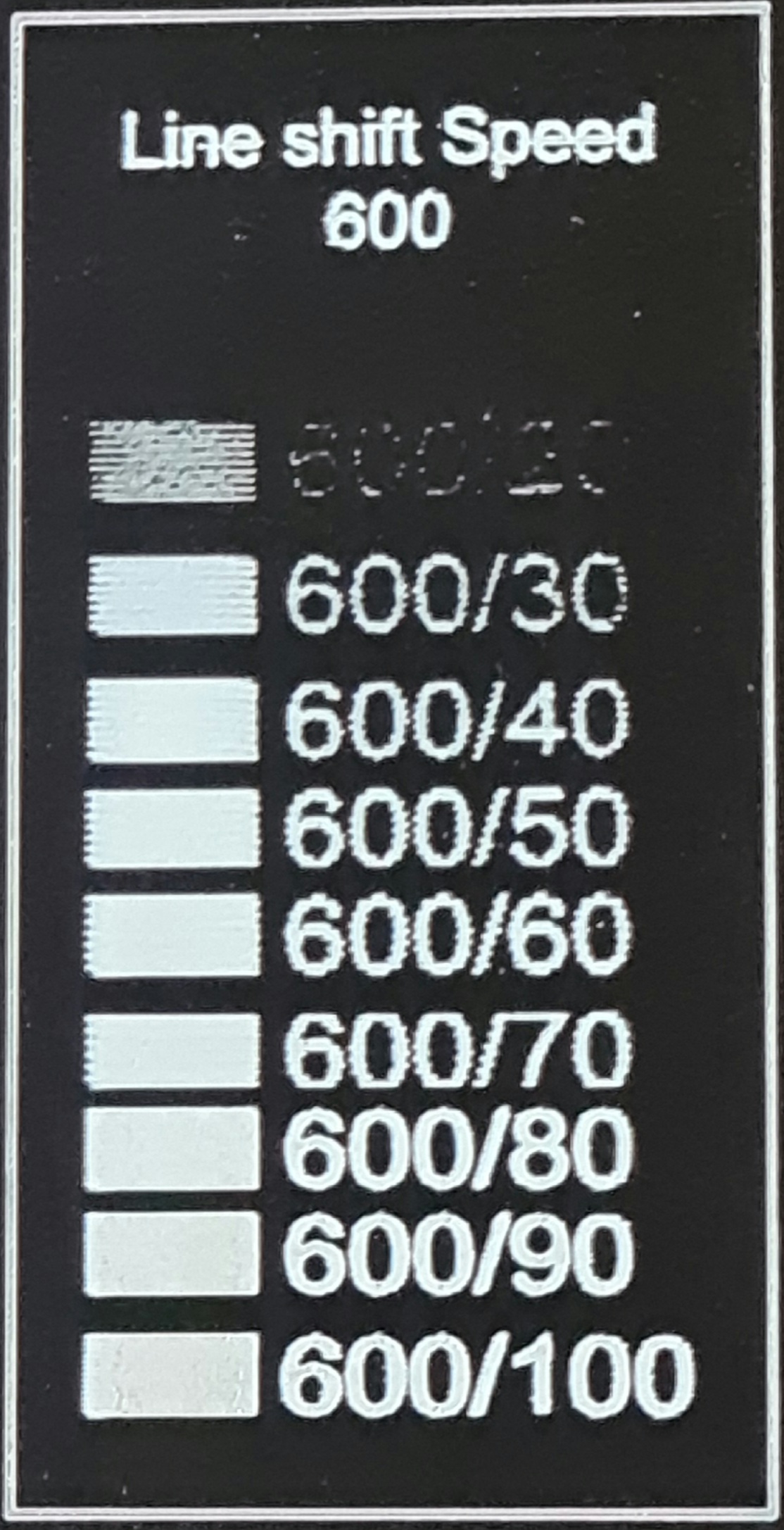
Line shift Speed 600 A.lbrn2 (262,8 KB)
Line shift Speed 600.lbrn2 (262,9 KB)
Overscan Test.lbrn (144,8 KB)
why are the overscans different?
This at least confirms the initial diagnosis that the issue is indeed resulting from an offset at all power levels since you see the same scanning result irrespective of power.
I’d suggest revisiting the scanning offset.
I’m not certain but it’s possible that your minimum power value for the cut settings may be throwing off your results. Try increasing that value to much more closely match the max value for each power level.
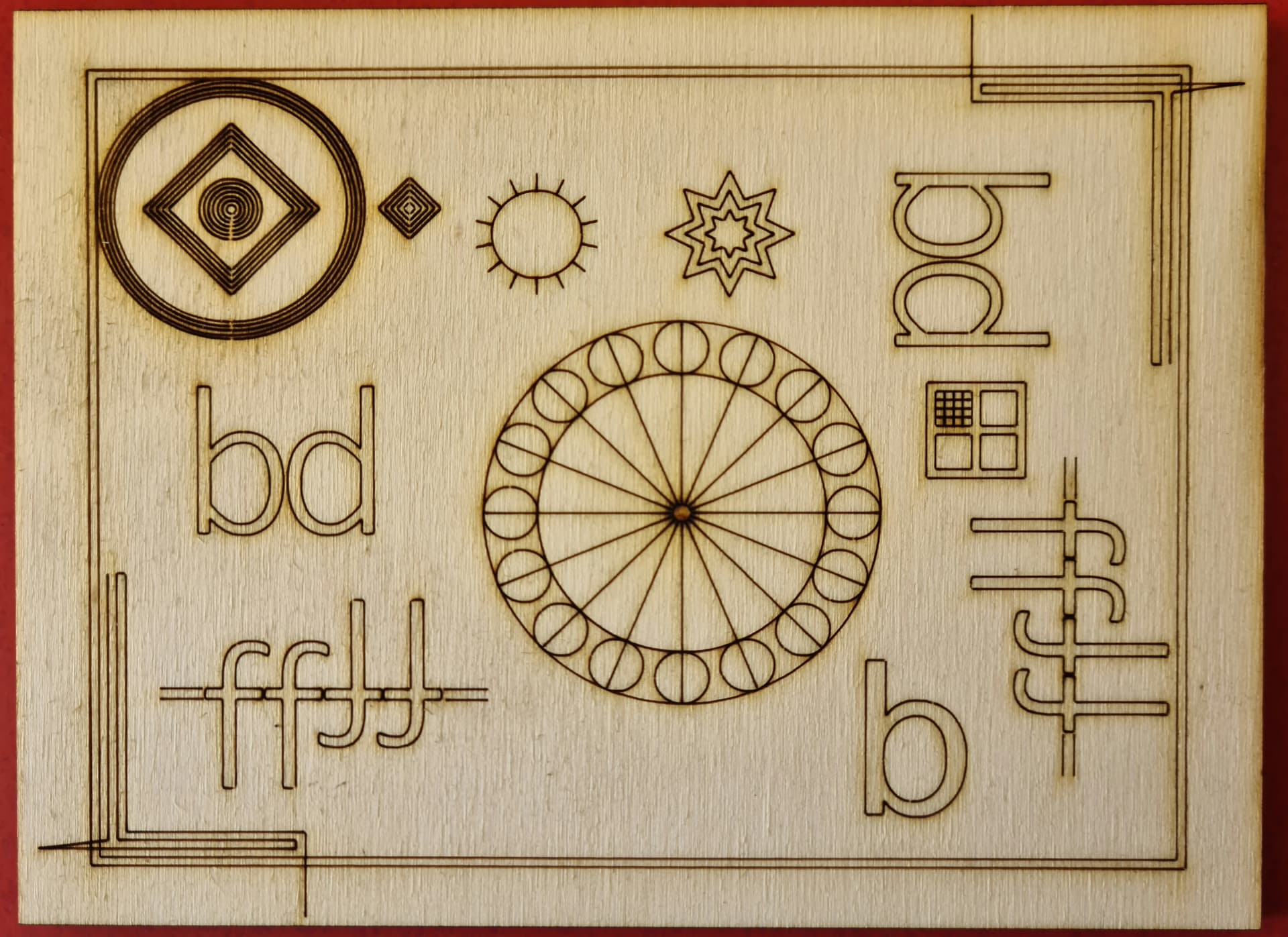
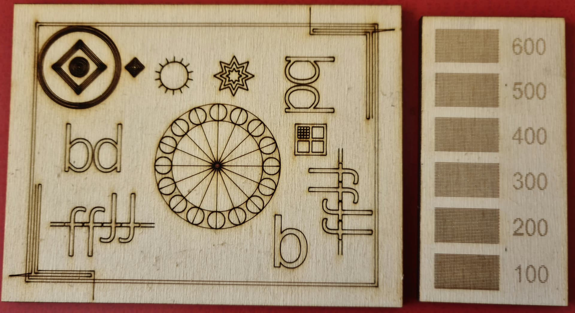
Also, test to see if you have any noticeable backlash in the system. Run a circle test to see that the ends of the circle meet at the same position.
how do I do that?
GrundTest.lbrn2 (76,4 KB)
In Cut settings, each layer will have a Max Power and Min Power value. Increase the Min Power value.
The backlash test is reasonable although there are some areas of odd artifacts. I suspect those are from low min power value paired with your 100W tube.
What do you mean by that?
May I ask if your machine has ever before been able to engrave at 600mm/s in a good quality?, can you show some older comparable projects?
I know very well that Omtech advertises speeds up to 600mm/s, but the conditions and results for those speeds have never been documented, or rather I couldn’t find them, so it will be very interesting.
No, it’s still new so I assume it’s pre-calibrated
Everyone here has told you, your speed it too high. You should target around 300mm/s.
Filling a object, your tube runs the same amount of power for the whole line.
Minimum values in a fill are ignored, speeds will never be below the set layer speed.
When you run something that dithers, you cannot control when the tube lases quick enough.
Until you back off those speeds and get things working, it’s going to be problems. If not here, then when you do something other than fill.
How do you know how fast you are going when you set it to 600mm/s?
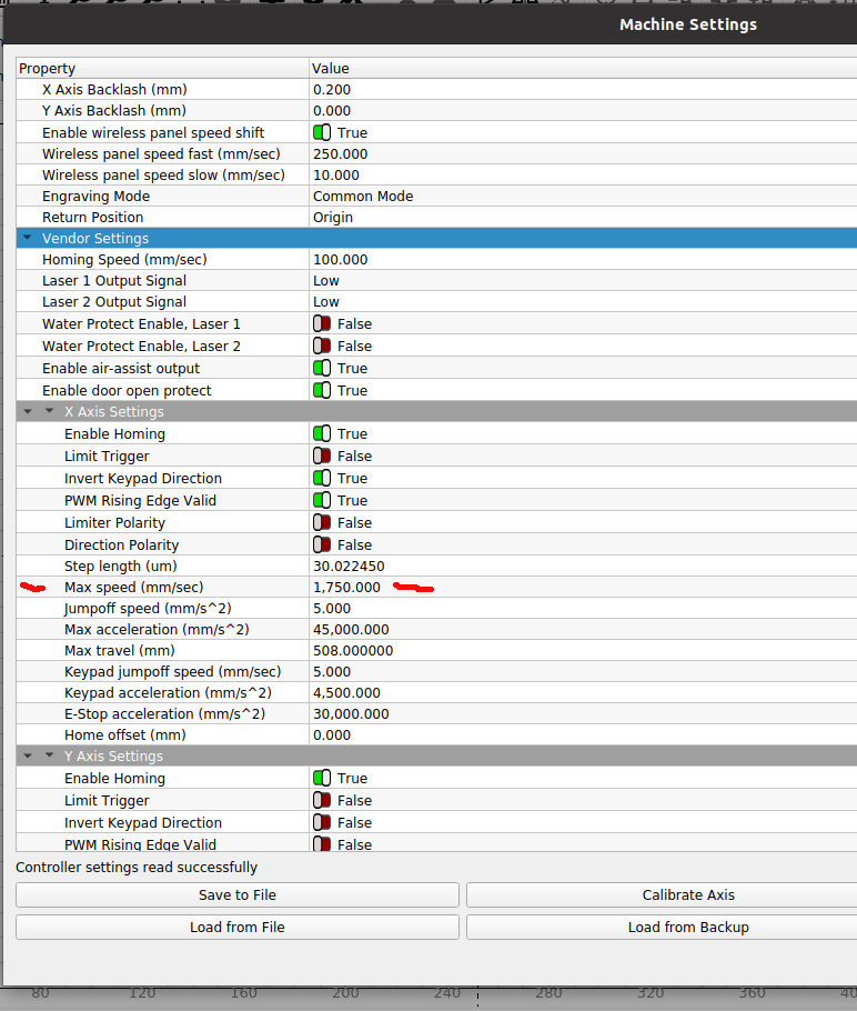
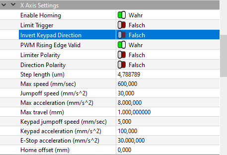
Check what the machine speed limit is and let us know… mine is 1750mm/s. Doesn’t mean it will run that fast, only that the controller will limit speed to that setting.
Help us help you, humor us and slow it down. After it’s functional, have at it.
![]()
1 Like
How can I tell that I have reached maximum speed?
ok, now I understand better, I thought you could run these small topics before in a better quality.
I would be very surprised if there is someone with a standard OMT machine that can produce your files in good quality at 600 mm/s, I can’t. It could be that @jkwilborn with his modified nozzle holder can handle it but I doubt it. The other aspect in this file is that your Cutdistance is 3337mm and your Rapidmouves is 18864mm! The whole process is 0.01 sec. slows down by halving speed to 300mm/s. - I would prefer significantly better quality for the price of 0.01 seconds.
obs. this answer has been delayed and overlaps some posts, sorry
???I’m just confused