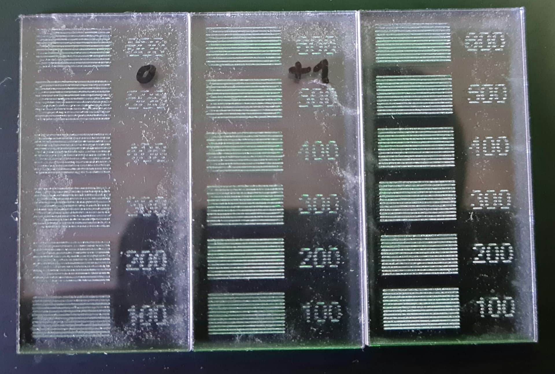
2 lines have a shadow here and 2 don’t
The lines should have the same thickness
The shadow is created at the start of the line. At the end of the line there is no shadow
The material looks like wood, which is poorly suited for precise results because the visible damage depends on the grain and fiber density. A uniform material, like the acrylic I suggested earlier, will allow you to focus on actual laser performance.
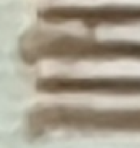
Although the laser turn-on and turn-off times should be symmetrical, they are not. A very close look at an acrylic test piece shows the differences:

The tapered ends show the laser tube turn-on time, with the power increasing rapidly. The rounded ends show the faster turn-off time. The round dots come from the typical behavior of CO₂ tubes at low power, which is exactly the regime your tube will operate in while engraving.
The slightly irregular patterns along the length of each line come from the chaotic behavior of the current through the tube. A very close look at the tube current shows it is not continuous at very low power:

You will never see that level of detail on wood. Wood has different behavior, so you must work from that basis.
You cannot achieve perfection, no matter what expectations you have for the machine or what the seller told you it could do. There are mechanical limits on its stability and accuracy, physical limits on the tube’s behavior, and chemical limits on the material it’s damaging.
You can improve the machine’s performance by following the test sequence I laid out for each material. There are no shortcuts, no magic, and, regrettably, no perfection.
Not perfect, no, but much better than what you started with!
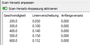
In principle, the Scanning Offset Adjustment values should be fixed for all materials, because it compensates for controller-to-material delays.
In practice, stray energy around the focused spot will damage delicate materials at differing diameters during turn-on and turn-off, so you may need slight timing variations. I avert my eyes and define the results to be Good Enough™ for my simple needs.
However, the Line Interval during Fill operations definitely depends on the damage diameter, which is why it’s part of the layer settings along with speed and power, and deserves attention when you’re testing a new material.
Eventually, your Material Library will have all these details for each material you use and you won’t even think of them.
Until you replace the laser tube and find it has a much different power for the same PWM percentage, whereupon you get to test everything all over again. ![]()
Well, great, those are great prospects
A separate overscan for each material. Would it be an idea if a kind of overscan library were possible that could be connected to the material library so that the appropriate overscans are also included when selecting the material?
Maybe that would be an idea that could be realized
another question question what is PWM? maybe PWM =pass word manager?
Be careful of the terminology; I know what you mean in this context, but …
“Scanning Offset Adjustment” compensates for the laser turn-on and turn-off delays. It matters most for high-resolution uniform materials like acrylic and, unless it’s grossly wrong, very little for fibrous stuff like wood and MDF. There’s no point in attaching the values to specific materials because it remains nearly constant for most materials; set it on acrylic and forget it.
“Overscan” is the distance on either side of the filled / engraved area where the laser head accelerates and decelerates; the Ruida controller handles those computations. Because the laser is off, the overscan area has no effect on anything within the LightBurn layout, other than requiring it to be more than the overscan distance from the edge of the laser platform.
“Scan Interval” (or “Line Interval”) is the distance between successive lines in those filled / engraved areas. This differs between materials because of the effective spot size and is stored in the Material Library where you’d expect it.
In the context of laser machines:
PWM = Pulse Width Modulation
PWM is a cheap and effective way to convert a digital power level to an analog control voltage, without having to fuss with low-level analog signals inside the laser cabinet. The controller sends a digital PWM signal to the power supply, where it’s low-pass filtered to recover the average value to set the tube current.
To a good approximation, the CO₂ laser tube current is linearly proportional to the PWM value. For a tube with a 24 mA maximum current, a 50% PWM setting will run 12 mA through the tube.
To a mediocre approximation, the tube output power is linearly proportional to its current, so the power delivered to the material is roughly proportional to the PWM setting: 50% PWM in a 100 W tube = 50 W.
And, of course, each individual tube will deliver a different power to the material at the same current. The power will decline with the tube’s age / usage / average power / etc. If this matters, as it might in a production shop, you’ll replace a working tube when its power output falls below whatever specification you might have and calibrate the new tube to a known power output.
Such fussiness lies far beyond nearly all ordinary folks with lasers, but it’s been known to happen. ![]()
So I decided to check everything, starting with adjusting the mirrors (they weren’t adjusted quite correctly either, so there was a small line). I think the solution is simply a combination of many small errors that simply added up and resulted in this error resulted ![]()
I’m going to frame that! ![]()
Perhaps the moral of the story is that nobody cares as much about your results as you do, so they won’t pay as much attention to the details as you will.
Glad to hear you’re getting the (nearly) results you wanted!
This (nearly) is due to the fact that the alignment of the beam with the mirror to the tube and the focus lens is not yet quite perfect for me. I will correct that when I get the chance
This topic was automatically closed 30 days after the last reply. New replies are no longer allowed.