I’m currently using LB to export gcode to USB and then sneakernet the USB to the Snapmaker.
The file imports perfectly but after I set my origin and then tell the Snapmaker to run the outline, it is waaaaaay off - either just moving back and forth in a line (if I choose lower left corner for work and user origin) or tracing a square (actually a rectangle but the image is a 6x6 inch square) that is the wrong size and off the tile (if I choose middle of the tile for work and user origin). Despite the weird boundary trace, the tile burns perfectly well, perfectly aligned on the tile.
Having the same issue. From what I’ve read, the touchscreen “Run boundary” will not work. But the boundary functions in lightburn should if you’re connected to the snapmaker via USB.
If one of you with hardware can produce a simple file (like a circle or a square) using the stock software, and show me a GCode output that does frame properly I can try to mimic that.
My A350 laser is currently burning a large project (generated by Lightburn!), so I can’t double check the gcode file, but here are files generated by Luban (Snapmaker’s program - you can dl for free at https://luban.xyz/ ) and Lightburn. Note the A350 wants laser gcode files named .nc.
I tried to get both programs to generate the gcode with the center of the design as the origin.
I hope this helps - my burn will take another 2 days (!) - a 12 inch round 600 lpi 2 pass wood plaque) but maybe you can see if these gcode files solve the mystery?
I’ve added the min/max info to the header. I don’t have a thumbnail or a couple of the other bits, but I’m hoping those are treated as optional, not required.
I have the same issue, generated some gcode in LightBurn and saved it to a USB to find half the image burning on my product and the other half firing at my machine bed…
I just started using Lightburn to try it out and I do see that the latest version I’m using (0.9.20) does have the max_x and so on coordinates in there, but I think the problem stems from them being written in there as absolute coordinates assuming to bottom left as the starting origin.
The default origin for the Snapmaker is the center of the picture, so here’s an example of the bounding with a file created using luban:
;max_x(mm): 27.4
;max_y(mm): 37.53
;max_z(mm): 0
;min_x(mm): -27.4
;min_y(mm): -37.53
;min_z(mm): 0
While what I got generated from lightburn was absolute based from bottom left, even though I have the Job origin set to the center (and the gcode that actually does the burning does originate from that User Origin center correctly):
;max_x(mm): 223.6
;max_y(mm): 252.91
;max_z(mm): 0
;min_x(mm): 108.35
;min_y(mm): 94.92
;min_z(mm): 0
So I think the fix is that lightburn needs to take into account the Start from User origin and set the max_x and so on coordinates based on the User Origin.
Is there at least a temporary fix before changes are made to lightburn? Or just wait to see? I’m loving the software besides the issue it has with my Snapmake 2.0 A350 and running the boundary, but I’m hesitant to purchase the software before I know I can line up a burn successfully.
If you place your shapes at the origin in LightBurn, and turn off the toggle in Device Settings to discard out of bounds shapes, it should all just work using Absolute Coords too. It might look a little funny on screen, but it should function as expected.
The newest version did initially seem to address boundaries on a couple of my cuts but on others, it was way off. Right now I can’t recall if it was due to having the gcode exported with start from “Current position” or “User origin” or if that made any difference at all. I have decided to not rely on the boundary function on the A350, at least with LB v0.9.20.
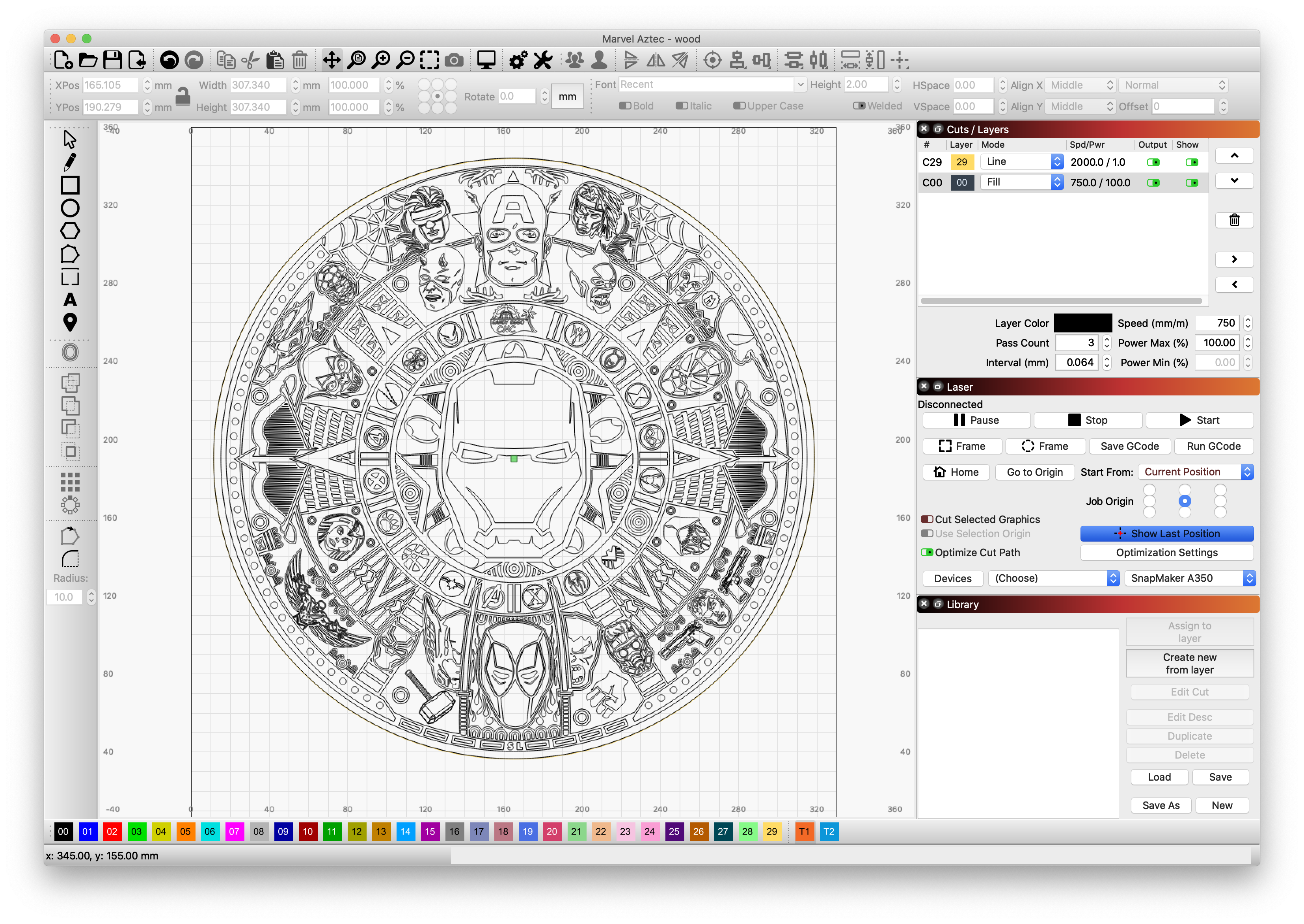
In the end, I just drew my own boundary, or duplicated the outer edge of a circle (I was engraving a 12 inch round wood disc), and made that a layer to do a line at 2000 mm/sec, 1% laser power then set that layer to be the first cut. I then set the origin on the machine (and in the LB software) to the exact center of the circle.
After hitting start, the laser will trace a low output 1% beam that I can watch and be totally sure it tracks perfectly on my wood. After that first trace, it would then do the engraving. This worked perfectly for a 72+ hour engraving.
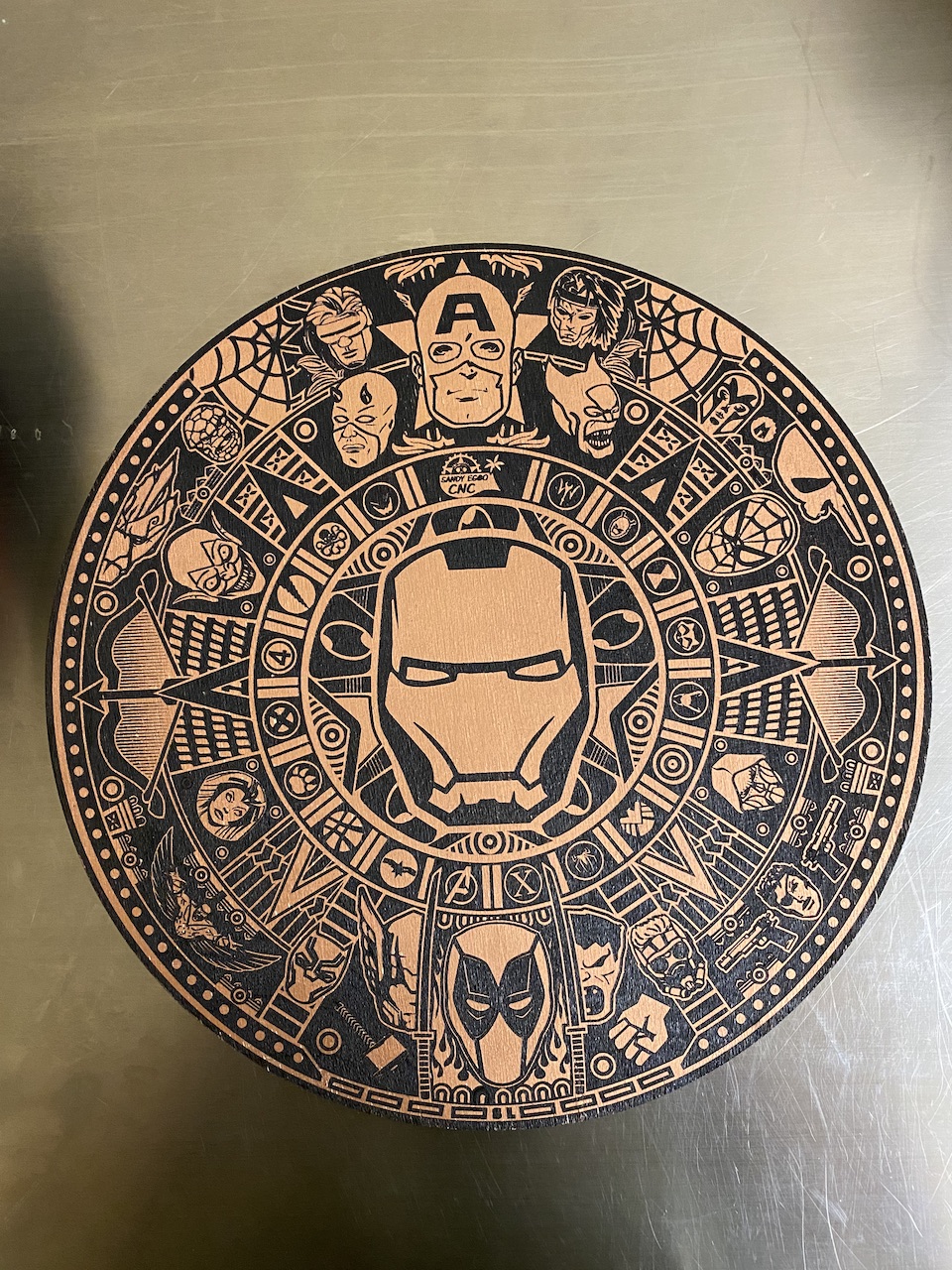
Tech notes: the above was burned with the settings in the screenshot, 3 passes at 100% to try and get some depth. I had used rubnbuff over the whole surface of the wood to make the copper color, then covered it with transfer tape (normally used for vinyl cutouts), did the 3 pass purn to burn away the paper and engrave the wood. I then spraypainted it all black and after the paint dried, removed the transfer paper and it left a really clear image.
@ConsummatePro I have seen your write up on tile burning in the Snapmaker forum and have to say its a great little piece, fancy giving a good write up on how to export and use the gcode from Lightburn with Snapmaker as I find that Lightburn fails to communicate with Snapmaker for long burns and ends the job after about 4hrs. I presume you wont have that issue when you export the gcode to a USB and run it from the Snapmaker directly. Effectively how do you do it buddy?
I’ve always used exported g-code uploaded via USB. Not convinced LB will reliably control the Snapmaker 2 since the author doesn’t have one to test directly and I understand the Snapmaker might be finicky for that control.
In the wood Marvel Azetec burn above, it was on a 12" round wood, and the burn took about 48h - I’ve done others as long as 72-80 hours for the same size, since the laser is so weak it needs many passes to make a decent depth of etching. None of these failed over that long time. All were done with USB upload of the file.
Steps:
Export gcode from lightburn - I make sure the job origin in LB is set to match how I will set the origin on the Snapmaker. I also choose “start from” current position - but it seems to work just as well if you start from “user origin”. Also make sure you rename or tell LB to export the gcode with a .nc file name as the Snapmaker will ignore it otherwise (LB saves it as .gc). I can’t find a setting to make this a default save option.
At the Snapmaker: using auto mode, I set the material thickness. Then, I use the jog controls to perfectly set the laser to the origin (in the round design above, the perfect center of the round wood, or on a tile, exactly to the lower left corner of the tile).
I also write down the XYZ coordinates for the origin in case I need to repeat the job. I have the workpiece butting up against stops on the laser plate so I can do multiple same sized pieces if needed. These were 3d printed.
Make sure to press the “Set origin” button. For good measure I also press the “move to origin” button
Then press “Start”
To ensure this is perfectly keyed to my object, my first burn is an outline of the object at 2000 mm/min and power 1% – see the above screenshot - C29 is a line that is the very outside of the design. I then watch as the laser traces 1% power and if it deviates off the desired spot, I stop the job and re-position the home. I’ve found that if you stop a laser job, you have to fully shut off and restart the Snapmaker as it doesn’t seem to zero back to home for the next job.
I’ve now done multiple projects all with great success using this method.
I found the last missing piece @LightBurn
I just by a lot of trial and error added and removed the header lines that snapmaker generates to the output from lightburn to figure out what was missing and it turns out that the file_total_lines header is required for the boundary running to work correctly on the machine. The line count doesn’t actually seem to need to be exactly right, but without the header present the run boundary is not working correctly.
So here’s a valid working sample of what the Snapmaker 2.0 needs header wise to for the boundary outline to work: