Good’ay y’all!
Let me first say I have 100% scoured the forums/Dr. Google and have had no luck finding this exact thing i’m seeing. Your input is greatly appreciated.
I have an Aeon Mira 7 with closed rail gantry. New tube/power supply about 2 months ago
I was experiencing some odd issues that have since been resolved with cleaning the snot out of all the snotty places. What I thought was an easy moving gantry… after cleaning i could send it to the back with an easy push… lol.
My lines are almost straight so I know the belts/gantry are functioning correctly… To the naked eye, they are straight, microscope… you can see some things. My engraves after the pat down have gone back to the insane quality I capture before.
I decided to do a scan offset from 0 again to just start fresh. When looking at the .5LPI tests, they look perfectly aligned. When looking under microscope, I can get them to line up on the right… but the left side(starting side) never lines up… Or I can get them to align on the left, but not the right. Like I said, to the eye- minor shifts under microscope can’t be seen with the eye.
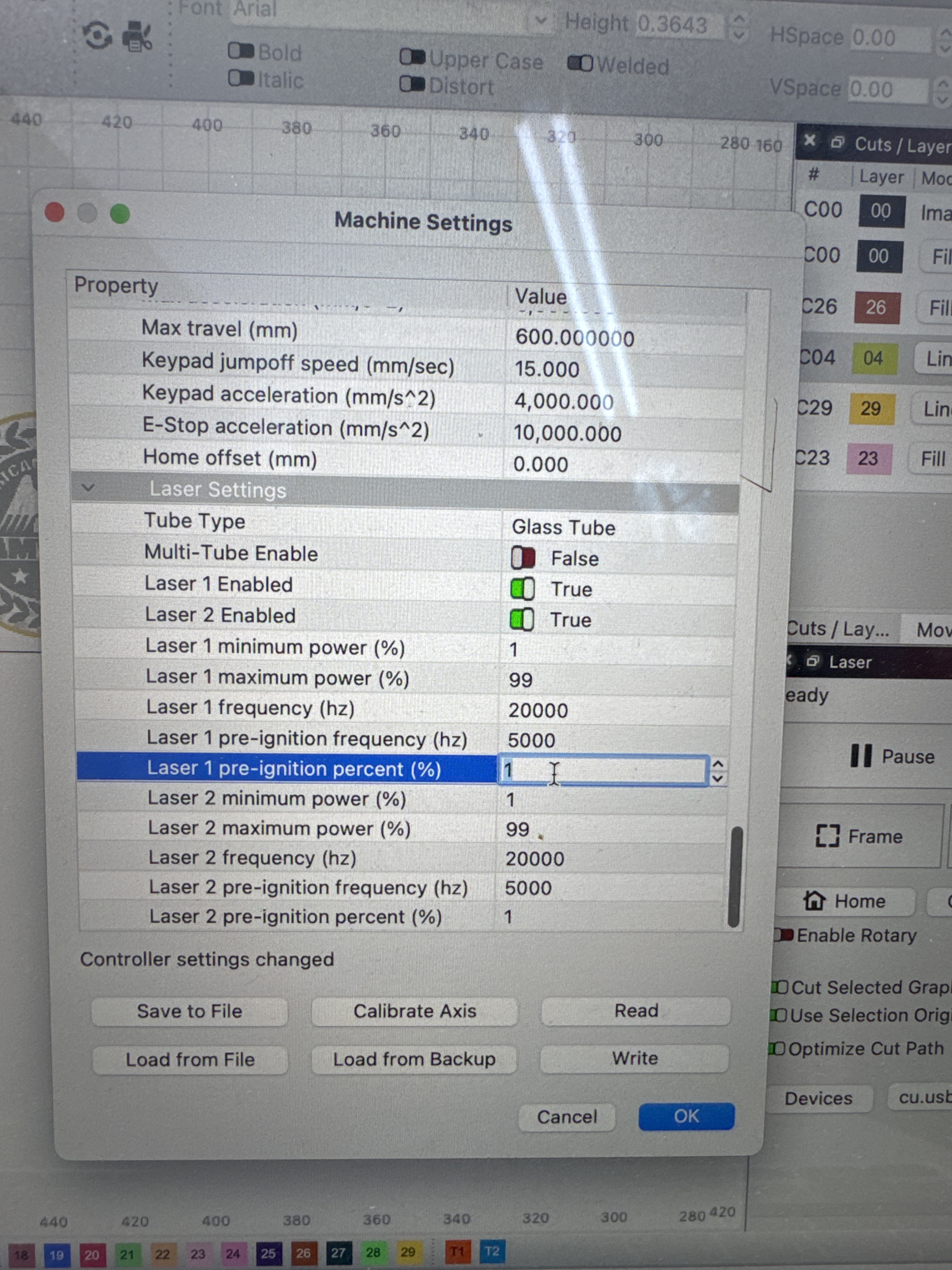
Initial offset doesn’t seem to cover this? What setting can fix this, timing? Would initial power % help fix this at the beginning of the engave line? Before I jump into slowing the accel down on X or Y… I would like to try and remedy what looks like a timing issue first.
Bi-Direction is on.
Am I being to critical and send it? I’d like to try and hone in more detail… I run the machine at 400/317 and pull of some incredible detail for a Co2 machine.
3 pictures below.
Right Side
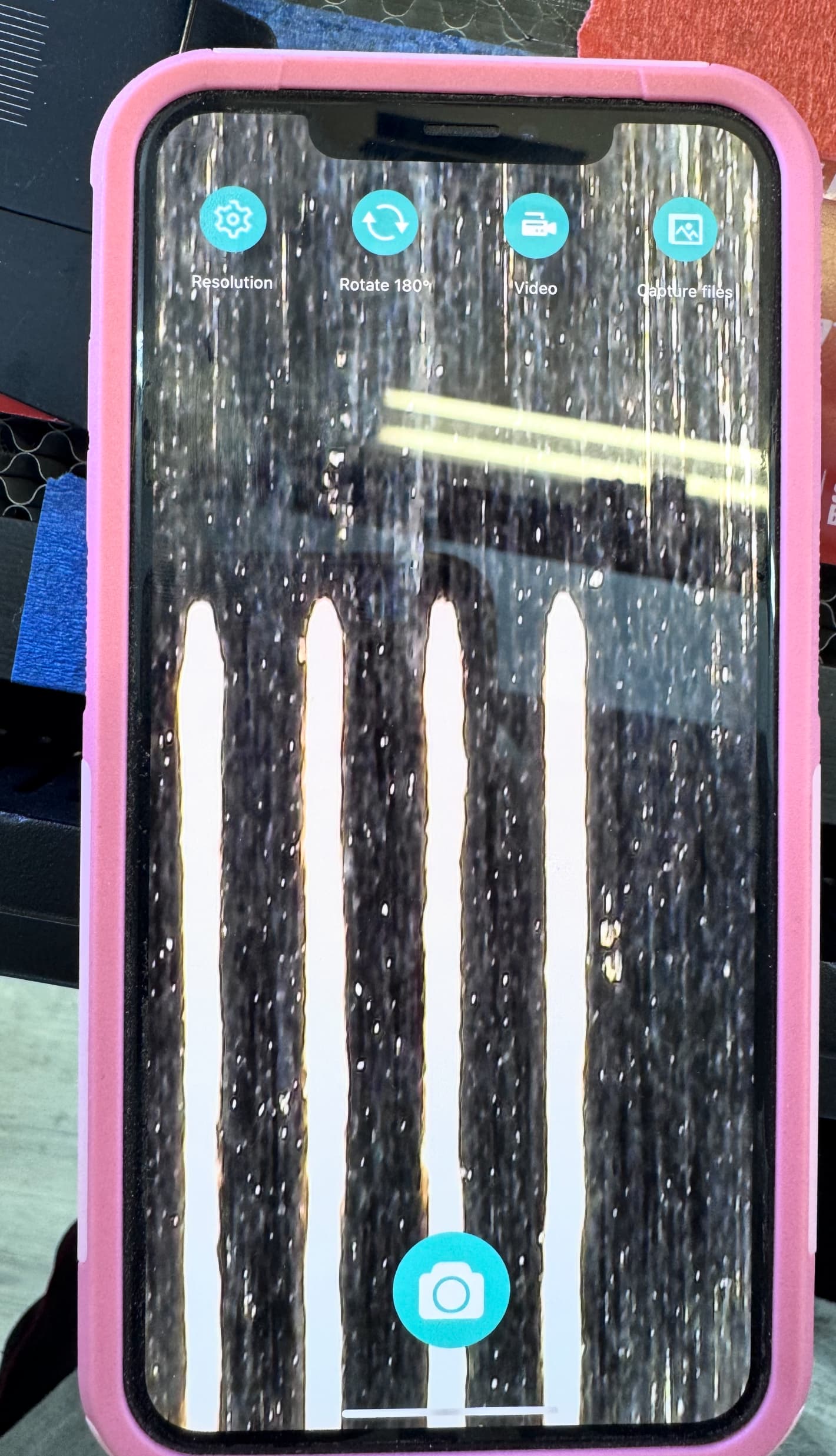
Left Side
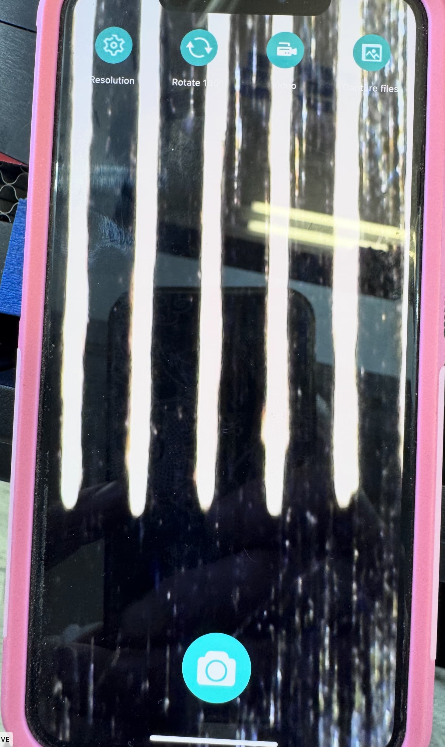
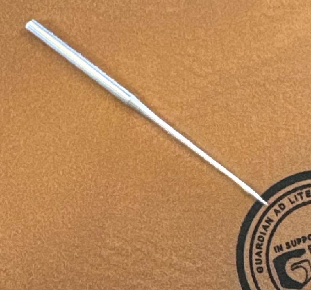
The circle outside of the letters is the size of a dime, thats a 65/9 commercial sewing needle which is slightly larger than your average house sewing needle. I started to see some of the aforementioned issues around this job, however - all of the letters are 100% readable for being that small. Was run at 400/317 - 1 pass.
thanks for taking the time to read!