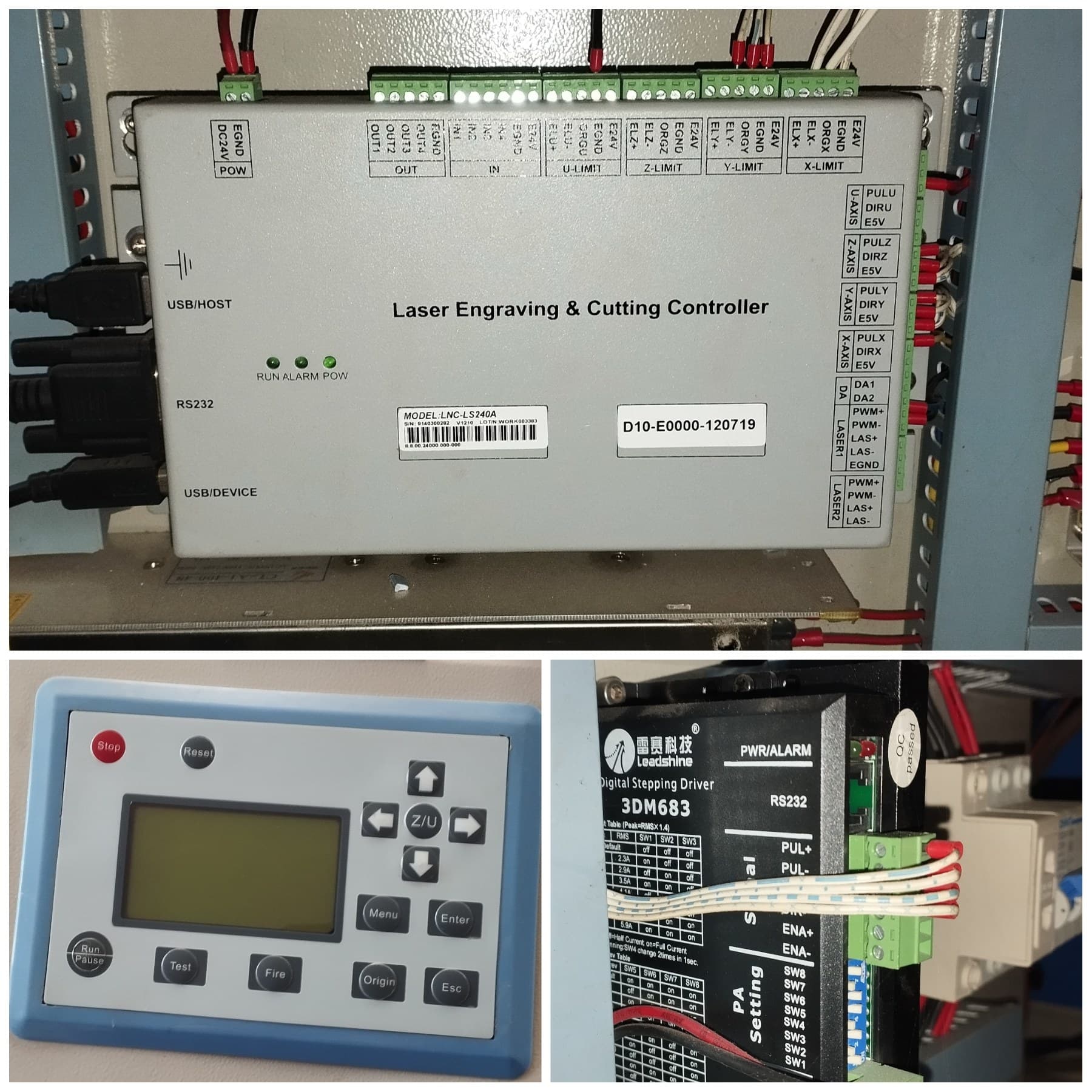
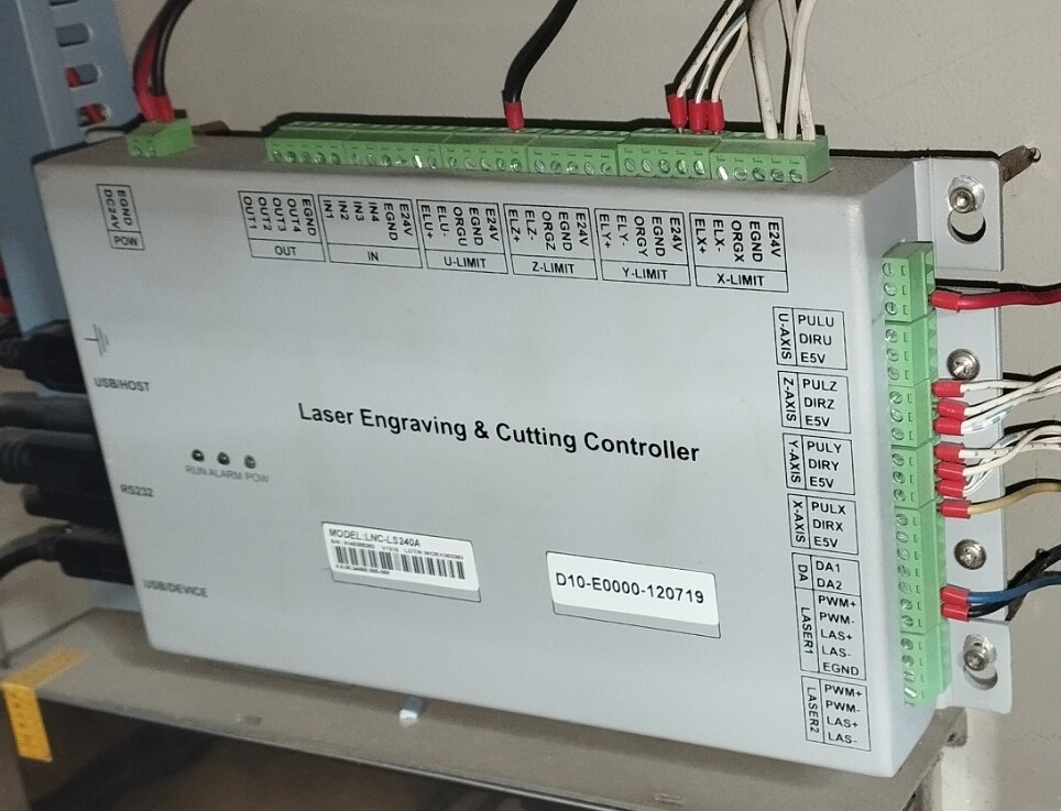
I’m reaching out because I need some help with an issue I’m facing. I currently have a JQ1390 CO2 laser (working area 130x90cm, 100W laser tube) that is equipped with an LNC-LS240A controller and a Leadshine 3DM683 digital stepper driver. Unfortunately, I don’t have much experience with this kind of stuff, and I’m wondering if it’s possible to replace the controller with one that is compatible with Lightburn.
I’ve found the Ruida 6445 as a potential replacement, but I’m unsure if that’s the best option or if there are other controllers that would be easier for me to install. Does anyone have experience with this kind of upgrade or suggestions on what controller might be the best fit for my machine? Maybe is this controller supported by Lightburn?
Thanks for the response, Jack! I will order the Ruida 6445 in the next 3 weeks. Since I’m new to this, I’m going to take a structured approach to the installation:
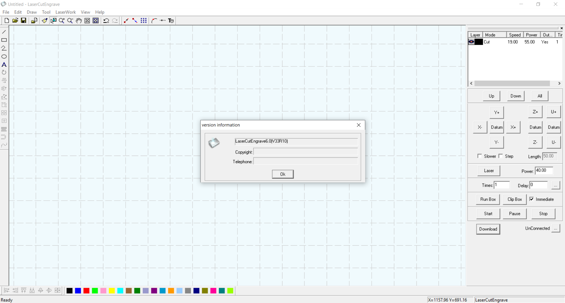
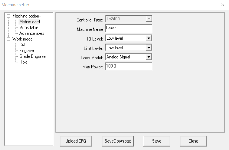
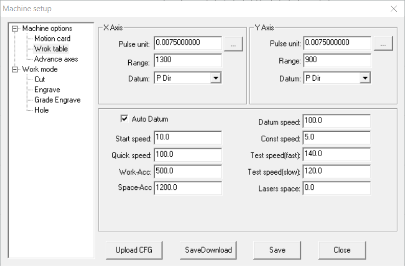
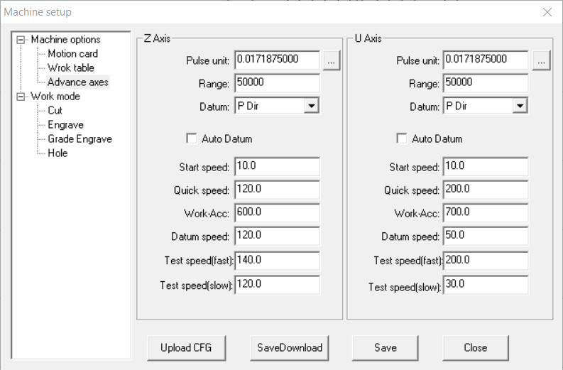
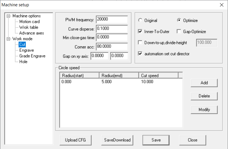
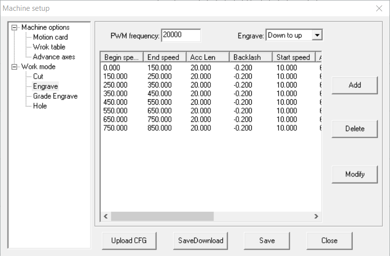
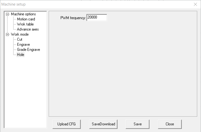
First, I’ll gather as much configuration data as I can from the old software. I’ve seen recommendations in another thread about this, and I’ve already taken some screenshots… But I’m not entirely sure if they contain the necessary settings. If anyone can confirm, that would be a big help.
Next, I’ll create a simple wiring diagram using photos from my machine. I’ll share it here before making any changes to ensure everything is correct and to avoid damaging anything. Plus, it might be useful for others attempting the same upgrade.
After that, I’ll install the trial version of LightBurn and start configuring the new controller there (If that’s possible. I’m not sure if there are any limitations beyond the 30-day trial period, so any insight on that would be appreciated)
Finally, I’ll verify that everything is working properly. purchase the pro license along with the LightBurn camera and mount, since that seems like a logical and straightforward upgrade.
The laser itself is fully functional but about 12 years old. It originally belonged to my father, who passed away. The machine only has X and Y axes… No Z, no air assist control, and no safety switches… Which I assume simplifies things, though I’d appreciate any insight on that.
Sorry for the double post, but I’ve taken more photos and looked more at the manual for the Ruida 6445 controller, and I’m still unsure where all the wires should go. Some connections are obvious after going through the manual, but others I have no idea. I’ve compiled a list of what I have so far:
POW DC24V Goes to CN0 +24V
POW EGND Goes to CN0 GND
U-LIMIT EGND Goes to ?
Y-LIMIT ORGY Goes to ?
Y-LIMIT EGND Goes to CN4 GND
Y-LIMIT E24V Goes to ?
X-LIMIT ORGX Goes to ?
X-LIMIT EGND Goes to CN4 GND
X-LIMIT E24V Goes to ?
U-AXIS E5V Goes to CN3 Puzu
Y-AXIS PULY Goes to AXISY PUL/cw
Y-AXIS DIRY Goes to AXISY DIR/ccw
Y-AXIS E5V Goes to AXISY +5V
X-AXIS PULX Goes to AXISX PUL/cw
X-AXIS DIRX Goes to AXISX DIR/ccw
X-AXIS E5V Goes to AXISX +5V
DA DA1 Goes to ?
LASER1 LAS- Goes to ?
LASER1 EGND Goes to CN5 GND
If anyone with experience can shed some light on the wiring, I would really appreciate it! I’m still learning about this stuff, so if I misunderstand something, I apologize in advance. I can provide more pictures or details if needed.
Seems sensible that the power goes in the POW connector.
Assuming these are active home switches, since they have a 24V supply. You can pick up 24V anywhere on the Ruida, but I’d suggest you pick this up from the 24V power supply, although the Ruida should handle it ok.
Both limits switches will go to the negatively marked axes limit, X would go to CN4-4 LmtX- input of the Ruida. The other two wires are ground and 24V power for the switch.
I suspect the ORGY is their name for the machines origin for the Y axes.
Since you don’t have a U axes, I have no idea where they are using the ground EGND. The PUZU is a 5V pull up if you need it, relative to ground it’s 5V so it’s likely they just picked it up to use it elsewhere… you’d have to chase it down.
These 5V taps are current limited, so check it in the manual if you decide to use them.
Seems like all of these are for the laser control. I am clueless as to what they use the DA and DA1 are. You’d have to look up what they use it for.
LAS is likely laser enable and you want the LAS- to go to the L input of the laser power supply (lps). This goes low to enable it to lase at the current power setting.
This should get you started… Sing out if you have any more questions.
Thank you again, Jack! That does helps a lot, I was able to fill in some of the missing connections. I’m still not entirely sure if everything is correct or safe to wire up as-is, but I have time to figure it out since the controller hasn’t arrived yet.
Here is the updated list:
POW DC24V Goes to CN0 +24V
POW EGND Goes to CN0 GND
U-LIMIT EGND Goes to CN4 GND
Y-LIMIT ORGY Goes to CN4 LmtY-
Y-LIMIT EGND Goes to CN4 GND
Y-LIMIT E24V Goes to CN0 +24V
X-LIMIT ORGX Goes to CN4 LmtX-
X-LIMIT EGND Goes to CN4 GND
X-LIMIT E24V Goes to CN0 +24V
U-AXIS E5V Goes to AXISU +5V
Y-AXIS PULY Goes to AXISY PUL/cw
Y-AXIS DIRY Goes to AXISY DIR/ccw
Y-AXIS E5V Goes to AXISY +5V
X-AXIS PULX Goes to AXISX PUL/cw
X-AXIS DIRX Goes to AXISX DIR/ccw
X-AXIS E5V Goes to AXISX +5V
DA DA1 Goes to ?
LASER1 LAS- Goes to ?
LASER1 EGND Goes to CN5 GND
I also found this in the LS240A manual:
DA1 - Laser 1 Analog output port (0-5V)
DA2 - Laser 2 Analog output port (0-5V)
PWM+ - Laser power differential signal (+)
PWM- - Laser power differential signal (-)
LAS+ - Laser high light LAS- - Laser low light
EGND - Laser power ground
But i’m not sure how these correspond to the Ruida controller. If anyone has insight into what those could be please post I will get a multimeter soon so I can try and trace wires as well.
The pwm from the controller goes to the IN of the lps. This input is actually a dual digital/analog input. Analog control one, as in most things, history, but these lps work with either.
You can use them to drive the IN of the lps, but I’d suggest you use pwm as most of todays machine generate.
Don’t know why I didn’t think of analog… I’m quite aware of it.
Thank you for the reply, I’m not sure I’m following… There are H, L, P, G, IN and 5V on the power supply.
H is unused
L needs to be connected to CN5 - L-ON1
P needs to be connected to CN5 - LPWM1
G needs to be connected to CN5 - GND
IN needs to be connected to ?
5V is unused
The P connection is the Water protect circuit in the lps, so it’s usually strapped to ground, making it active.
The Ruida should be wired to your flow meter or chiller and that should let the Ruida know there is an issue. If that occurs, the Ruida will stop everything… You can also fix the issue and continue.
Thank you for your time and replies Jack, I really appreciate your help! I didn’t even realize the water chiller was connected to the system… I completely missed the wire coming from it. It’s a CW-3000, and it has three wires coming out, but only two seem to be connected.
Here’s my updated wiring list so far:
This is the list so far:
POW DC24V Goes to CN0 +24V
POW EGND Goes to CN0 GND
U-LIMIT EGND Goes to CN4 GND
Y-LIMIT ORGY Goes to CN4 LmtY-
Y-LIMIT EGND Goes to CN4 GND
Y-LIMIT E24V Goes to CN0 +24V
X-LIMIT ORGX Goes to CN4 LmtX-
X-LIMIT EGND Goes to CN4 GND
X-LIMIT E24V Goes to CN0 +24V
U-AXIS E5V Goes to AXISU +5V
Y-AXIS PULY Goes to AXISY PUL/cw
Y-AXIS DIRY Goes to AXISY DIR/ccw
Y-AXIS E5V Goes to AXISY +5V
X-AXIS PULX Goes to AXISX PUL/cw
X-AXIS DIRX Goes to AXISX DIR/ccw
X-AXIS E5V Goes to AXISX +5V
From the LPS:
L Goes to CN5 L-On1
IN Goes to CN5 LPWM1
G Goes to CN5 GND
From the Water Chiller
Wire 1 Goes to G on the LPS and CN5 GND on the controller
Wire 2 Goes to P on the LPS and CN5 WP1 on the controller
Please correct me if I’m wrong,
I was really intimidated by this at first and thought I’d never figure it out, I’m actually feeling pretty confident about wiring it up. I’m excited to get everything connected and hopefully make this machine a bit more functional!
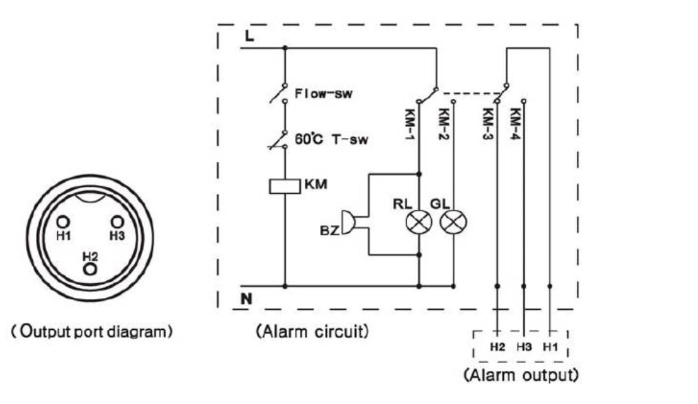
This is from the 3000 series chiller user manual and shows how the fault output is implemented. The manual I have, even translated is mostly Chinese or I’d post it.
If you think about the relay being in it’s other state, illuminating GL (green light). Now follow the H3 pin of the connector through the relay to H1.
This just completes the the ground for the WP input on the Ruida.
@jkwilborn If I understood correctly, I need to connect H1 to CN5 WP1 and H2 to CN5 GND. Additionally, on the LPS, I should bridge P and G to bypass the LPS’s built-in water protection and let the controller manage it instead. Did I understood that correctly? Thank you once again!
@Colin I’ve never done anything like this before… My only experience with this machine has been using it to engrave and cut keychains. But now, I want to improve it and hopefully turn it into a source of income, since I lost my regular job and can no longer work in my previous field.
I also want to document the process so that if someone else stumbles upon my post, they’ll have a clear guide on how to rewire their own controller. These controllers seem to be pretty common in my country, but I haven’t found much information about them elsewhere. Seems like it was just one importer importing machines with that controller and there are quite few around.
Hey Teddie, it’s still installed in my machine, and shipping from my location would be pretty expensive. I’d recommend looking into a more modern replacement instead. Once I’ve completed my swap, I’ll post all the steps I took so you can follow along (If I manage to pull this off ).