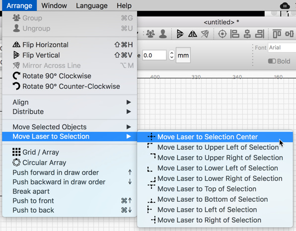
When using the camera and the Absolute Coords option set, I am using the “Set Laser Position” control a lot when positioning material now. It is a great tool and it really helps me verify my camera alignment.
The only thing that would make it even better would be if the laser position control would snap to nearest vector or node or center point of my geometry. Is that possible?
I think the click-to-position stuff snaps to grid units at present. It wouldn’t be terribly hard to add other snaps too - I actually have most of that tooling in place in a generic way.
Would it possible to use the new Print & Cut functionality (or something like it) to re-align the camera? It seems like if you can align on an object with two marks you can re-align the workspace with a single mark since it can’t rotate.
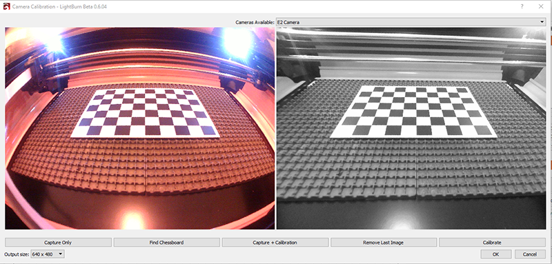
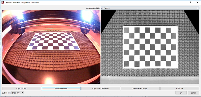
Camera alignment is much more complicated because the camera view correction supports keystone (reverse perspective) correction too.
Something I’m considering is having options marks that you put on your machine, not the bed. If you tag my markers first (so I know their real world locations) and then your own markers, I should be able to work out the real world locations of your added marks, and then let you use those to re-align without having to run the alignment job. Setting up the UI will take a while, but the logic works.
I am assuming that the full alignment process for the camera has already been completed and subsequently the only adjustment needed is X-Shift or Y-Shift. That is the mode my laser seems to be in.
Yes, what I am asking if LightBurn could use that corrected view plus a crosshair marker at a known location on the workspace to correct for any offset that occurs over time. I assume you have a mapping for each pixel in the corrected view to an absolute X/Y location on the workspace so if the known marker is not at the expected X/Y location then apply a X or Y shift to adjust so it is. Like the X and Y shift controls in the users camera window.
Possibly, but that assumes the calibration was right to begin with. If you have errors over time, at some point that simple shift wouldn’t be enough. For example, if you have your camera mounted with an adjustable rotation around Y, and that started to slip, the perspective skew introduced would mean that as I corrected for the shifting, one end of your workspace would appear to shrink while the other grew. If I have multiple markers and you re-tag them, I correct everything all at once.
I understand, I was just looking for a quick way to to do the second half of the camera calibration without needing to have the laser re-burn the four corner test pattern.
If I could guarantee that the four corner test pattern was in the same exact location on the workbed is there any way to complete the calibration without recreating the test pattern and just use the one already there?
Yes - that would work fine. All the alignment code does is map known, real-world locations (relative to the laser origin) into camera space, and then figure out a general conversion from that. It’s important that they are relative to the the origin though. If, for example, you have mechanical limit switches, and the arms on them flex a little over time, that would move your origin, and change the calibration.