I have a rabbit hx 6090. bed size is 900 x 600. I am trying to figure out how to set this size into the ruida controller settings. I cannot get it to go and zero itself either for some reason. I just installed this controller and am just trying to get it set up before trying to get the computer to work with it
It depends somewhat on which Ruida controller you have, but (in LightBurn) look in Edit → Machine Settings→ Vendor Settings → X Axis Settings → Max travel and similarly for Y Axis.
Use 900 for the X axis and 600 for the Y axis.
In both Axis Settings sections:
Enable Homing= TrueLimit Trigger= FalsePWM Rising Edge Valid= FalseLimiter Polarity= FalseHome Offset= 0.0
When you’re done, click the Write button to update the controller with the new values.
You can also set those values with RDWorks, but you’re pretty much on your own there. ![]()
Assuming the home switches work correctly, it should move toward the switches when you turn it on, bump once, move away, bump again, move away, and stop.
If it doesn’t behave that way, further checks are in order, so report back.
If this is in lightburn, under which menu item do I find it?
I dont have these choices in machine settings
The bottom Machine Settings section is Vendor Settings. It needs a click on the small triangle on its left to drop down all the settings:

You’ll get a stern warning about the potential for messing things up, but we’re well past that point in the script … ![]()
It is always wise to make a backup of your configuration before modifying anything. It’s very easy to change something accidentally and have a can of worms, but very easy to re-load the pristine version.
![]()
OK, I found those settings and they were all correct. When I turn it on it goes to the left rear, chatters some and then does a homing thing but ends up about in the center of everything. I have home set to the right rear in the controller because that is where the limit switches are. It never goes to that corner for anything
Depending on which controller you have (tell us, please!), you can poke the Esc button (or something similar) on the machine display to cancel the homing operation.
If you mean the “Screen Origin” (or something like that) set through the controller’s display / keyboard on the machine, that affects only how things are displayed there and has nothing to do with homing. If it’s set to right-rear, then it’s probably OK.
To set the machine homing position, do this for both axes in Axis Settings:
Enable Homing= TrueLimit Trigger= FalseLimiter Polarity= False
Because the X axis is homing in the wrong direction, in X Axis Settings change Direction Polarity from whatever it is now to the other thing: False → True or True → False as appropriate.
Then it should home to the right rear.
If the X axis arrow / jog buttons on the machine console now move backwards, in X Axis Settings change Invert Keypad Direction from whatever it is now to the other thing: False → True or True → False as appropriate.
Then it should move properly from the console and in response to the LightBurn jog buttons.
If it doesn’t, take screenshots of the current axis settings so we can look over your shoulder.
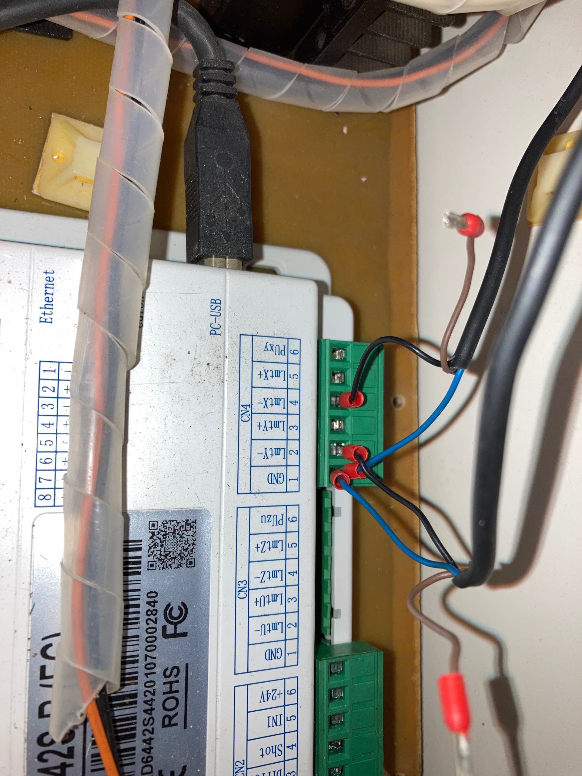

Given that I do not know where the other ends of those wires go, I cannot tell you much.
With that in mind …
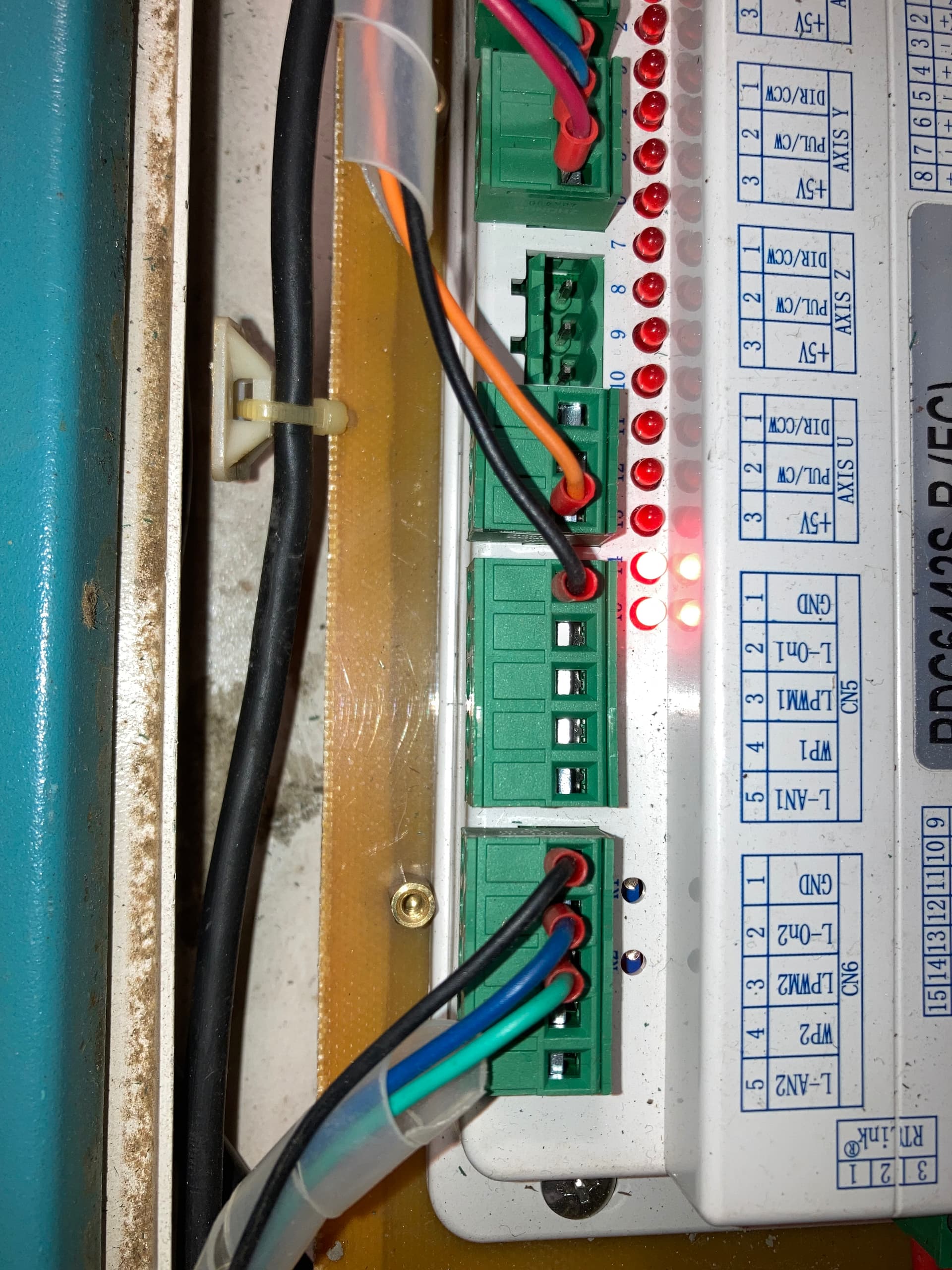
The control signals for the laser power supply are wired to the Laser 2 terminals in CN6, which is unusual for a single-tube laser. Unless you know that’s where they should be, move them to the corresponding Laser 1 terminals in CN5.
The cables from the home switches have three wires, with the brown wire dangling. Unless you know differently, the brown wires supply power to the proximity sensor circuitry inside the switches. The home switches will not work without power, so both brown wires should connect to a +24 VDC terminal.

Which one of those describes the situation? Are you using the Laser 2 control signals on CN6?
The wire colors at the laser power supply do not match the wire colors at CN6. The blue wire from L-ON2 seems to be spliced to a red wire that goes into the spiral loom. A black wire comes out of the loom and connects to Pin 2 = Active High Enable, which is the wrong polarity for the L-ON signal, which is generally active low. What happens out of sight between blue and black?
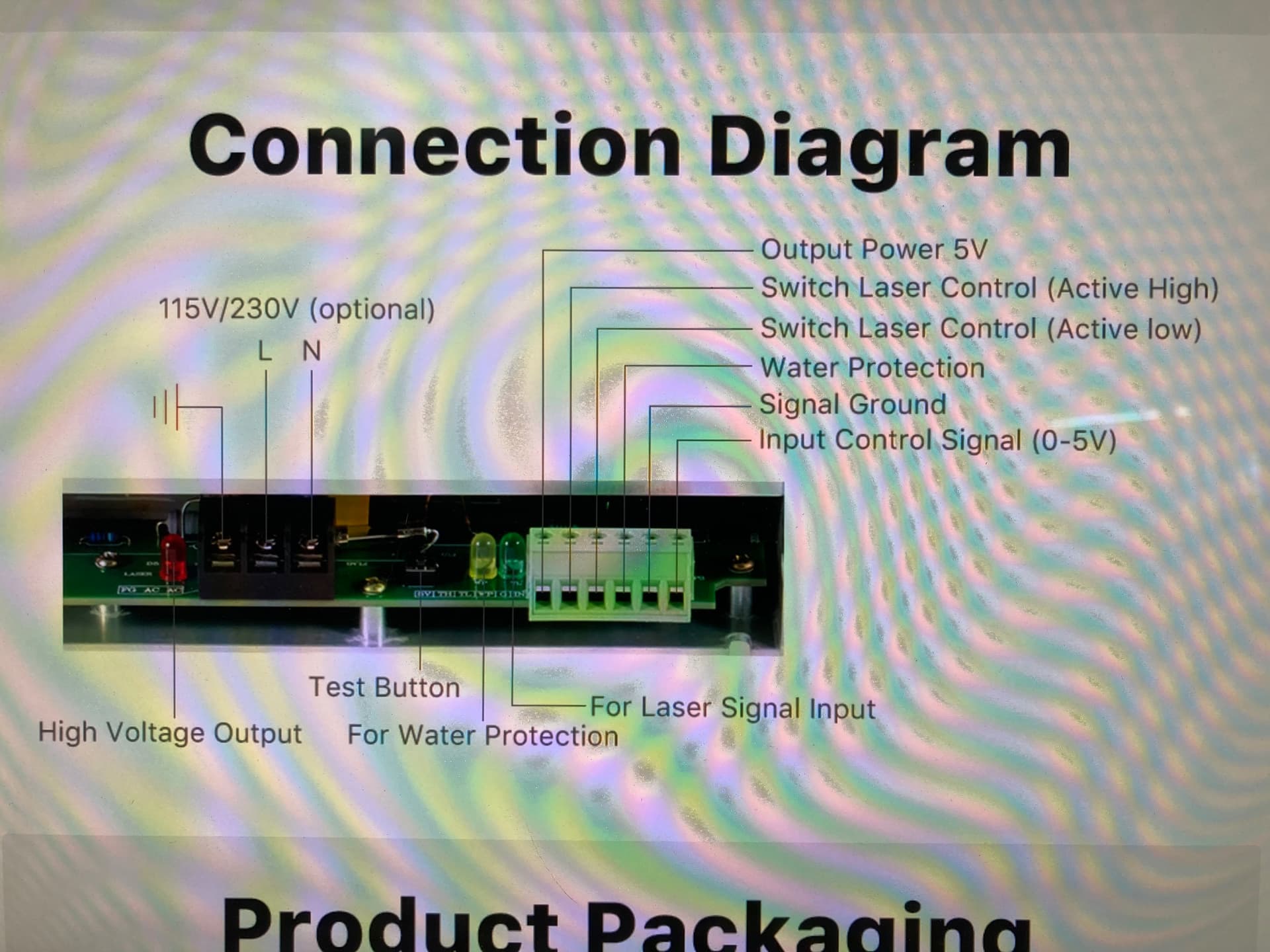
The green wire from the LPWM2 signal connects to Pin 3 = Active Low Enable. The power supply data sheet indicates this should go to Pin 6 = Input control signal.
The Black wire from GND connects to Pin 5 = GND, which seems correct.
Both the controller and the power supply have no connection at their Water Protect inputs. Given that no cooling flow will destroy a tube very quickly, why not let the controller or the power supply save the tube?
The lps only uses one laser enable, the H or L input, not both.
It should not lase as the WP input to the lps is not connected and is active low.
Yes, he’s using laser two, just change plugs. Wiring is the same if I recall.
![]()
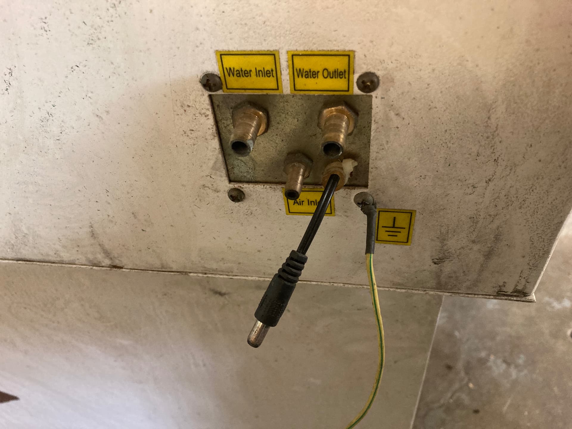
I sure appreciate you guys helping me. I am going to go over the laser controls with you right now and see if I can get that wired correctly. I have not tried anything with it yet… the blue wire from the controller goes through the top cover switch and ends up being the black wire in the laser active hi. attached is a diagram I made. I moved the wires over to CN5 as mentioned. for water protection… what do I wire in and where does it go? right now the only wires would be this little connector sticking out by the water hose connections.

I will come back to the motor movement control wiring and settings after we get this wiring confirmed that it is wired OK
Remove the H wire to the lps, it’s not needed.
| Ruida | LPS |
|---|---|
| L-On1 | L |
| L-PWM1 | IN |
| GND | P |
| GND | G |
There is a P input for water protection, on mine, it’s wired to ground make is active. The controller shuts down everything if it detects a fault.
It sounds like your machines lid protection goes through the P terminal.. Run this to the door protect of the Ruida, just like the coolant protection goes to the Ruida WP1 input. These just pull the input to ground level or active low.
Make sense?
![]()
This is a screen shot…

If you look over the connector, it has each pin labeled as I used in the chart.
IN is actually refereed to on the lps itself, but as Input Control Signal (0-5V) on the diagram.
IN controls or sets the tubes current limit. On machines like the Ruida, the pwm (or IN signal) is active the entire time the machine is executing that layer. The controller just enables it to lase when needed by pulling the L terminal low.
It’s set up to work this way, so you’re making more work and complications than I think you need too.
Did you get rid of the H wire? Either H or L but not both. Both are laser enable inputs, so you either have a active high or active low, but not both. The Ruida uses low active, so use the L terminal.
We’d all rather you slow down and take the time if you’re not following what we’re doing.
![]()
AHHAA. I see and have connected the wires as you indicate.
Now on to getting it to home and recognize limit switches. When I first turn on the head goes all the way to the right and goes all the way to the back and chatters for a while, then very slowly the head moves to the left for about an inch, then quickly moves out to about 6 inches and left about 6 inches. you can see by previous pictures how I have these wired on the controller
You’ll have to remind me… did this ever work? Did you upgrade the controller or?
Have you checked that the home switches are communicating with the controller.
You can see them activate by watching the leds and from the Z/U → Diagnosis panel on my 6442g.
![]()