The Ruida has the input for coolant (WP). The P (water protect) of the lps isn’t used with a dsp type and is usually wired to ground.
If the Ruida senses a coolant flow failure, it will shut down the operation. If you wire this to the lps, then the laser will stop lasing when the P input goes high, but the Ruida doesn’t know it and the machine won’t stop.
I have the lid and Water protect both grounded to the machine cabinet.
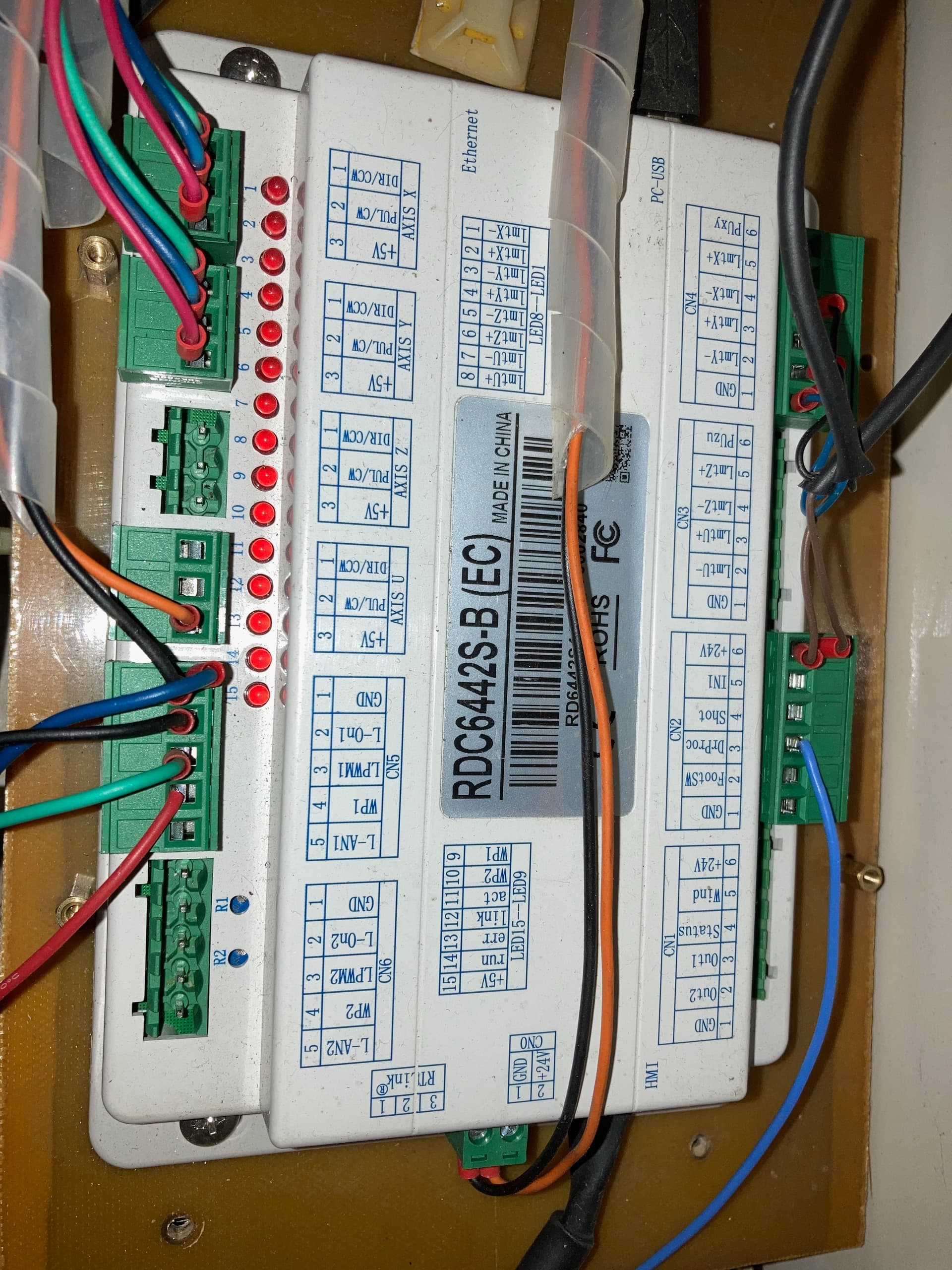
here is a photo of the ruida connections showing wp and the lid protect connections
We were speaking about the lps, not the Ruida. The Ruida will handle both errors if you wire the door to CN2-3 DrProt and the Chiller or flow sensor to CN5-4 WP1.
I can’t look at either the Ruida or the lps in a photo and tell where the wires actually go once they leave the photo.
OK, tested water protection, turned off chiller and pressed pulse, got error on console saying error water
did the same for lid protection got same result
I pressed the lid switch and tested, no error however still no laser beam. I am coming back to the idea that there must be something wrong with the signals coming to the lps
I even tried turning off the water protect in the vendor settings and that made no difference.
can I run a little wire from ground to each of those terminals in the ruida for the wp1 and the lid protect are connected to rule them out
Can you post a current picture of the wiring on the LPS?
In your previous picture in post 51, you do not seem to have the water protect pin on the LPS connected to ground. There should be a wire jumping between the 4th (WP) and 5th (G) positions (counting from the LEDs). The WP on the LPS should not be connected to the WP on the ruida.
Not asking about the switches. On your previous picture you posted of your LPS, you had nothing connected to the WP position on it. Do you have anything connected to the 4th pin from the LEDs on the LPS? Can you post a picture of the LPS showing how it is currently wired?
It takes the controller wired correctly AND the machine configured correctly for it to operate, along with working components
If it gives you a warning with both door and coolant protection, the controller is working.
You have to quit changing the wiring on this or I am going to give up. I warned you about this before. You’re clearly causing many of your own issues. We can’t help you with a suggestion, then you do a wiring change and try to apply that suggestion.
This should have been wired correctly by now, but you keep changing it.
As I mentioned before, if the signals are correct from the controller, the problem isn’t there. It’s likely a configuration issue. That’s where most of these failures occur, the only other option is a hardware failure.
Yes, Jack, I know this
I have not changed anything on the wiring. I was asked if I had the water and lid protection connected to ground and I answered that yes both of them were grounded to the chassis. I am quite sure I verified that these are both working. So I agree that there is probably a setting someplace that I am missing. So now I have verified that the lps is not the problem either because I changed it and still have this issue.
The problem comes in when someone else asks a question or makes a suggestion other than you, I try to answer them and no I am making no changes to the wiring. I am just at my wits end as to what I am missing. Thanks for your patience with me.
Jack
Nick made this post:
In your previous picture in post 51, you do not seem to have the water protect pin on the LPS connected to ground. There should be a wire jumping between the 4th (WP) and 5th (G) positions (counting from the LEDs). The WP on the LPS should not be connected to the WP on the ruida.
I currently have the wp connected to #WP1 on CN5 of the ruida and the other wire of the switch grounded to the chassis of the machine.
Can you clarify which way things should be
So far you have been the most help to me and I have followed your instructions. Before I make any changes I want to keep on the same page that you got me started on because you have been right so far on all this
These are two seperate systems. I’m advising you let the Ruida handle the faults instead of the lps.
The wp connection to the lps should be grounded. This will allow the lps to lase when needed.
L-WP1 is an input, as WP on the lps is an input. Most devices have an output that drives some other devices input…
L-WP1 is where your coolant switch to ground should be connected. This allows the Ruida to control any faults and to continue if the operator makes that choice.
This is from post 16.
I modified the post to reflect the P or WP input of the lps, although stated in the text right below the table.
OK, back at it again. I put a jumper from the WP to the ground terminals on the LPS. I have one wire from the water switch to the WP1 on the ruida and the other to a chassis ground. I put one wire from the lid switch to the DrProc terminal on CN2 of the ruida and the other to chassis ground. now the laser fires as it is supposed to. HOWEVER… I have no control over the power. Seems to be maybe at 10% max. I have the setting on the dashboard of the machine MIN Power. 5%, MAX Power 99%. Settings in the Machine Settings of Lightburn. min and max same as console. FREQ 20000. pre ig freq. 5000. pre ign. % 1.
I think I’ve seen a similar question on the official Ruida forums, but I’m not sure, so if you have time you can check out the official forums and maybe find the answer.