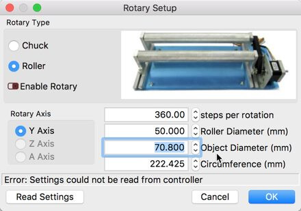
So I built myself a rotary tool for my engraver and I am trying to set it up in lightburn, but I have to be doing something wrong. When I go to tools and rotary setup and select the roller option, I get these value entry options:
mm Per rotation
Roller dIameter
Object diameter
Circumference
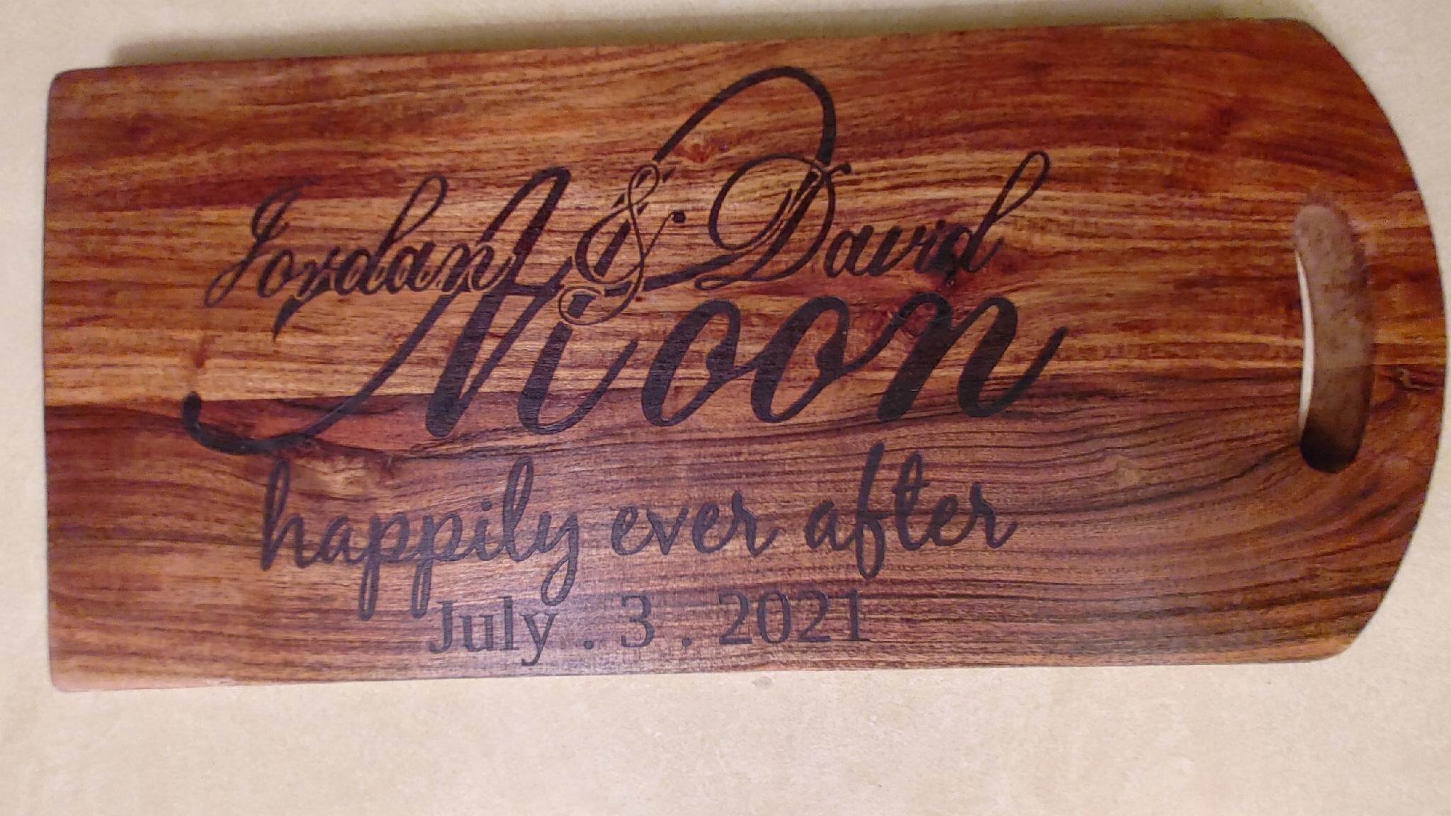
For mm Per rotation, is that per rotation of the roller or the object? Is the circumference the crcumference of the roller or the object? The roller diameter I would assume would be the diameter of one of my wheels, which is 45.4mm. The object is a drink bottle and it is 74mm in diameter. Are there other settings that I am missing? When I look at documentation of the setup it shows steps per rotation where mine says mm per rotation. The screenshot pic is not my setup, but an image from a forum post I found to show what others see vs what I am seeing.
Any help is appreciated.
You need the transmission ratio between the pulleys and your large rollers on which the bottle is located. You then enter that into “roller diameter”.
May bee that helps:
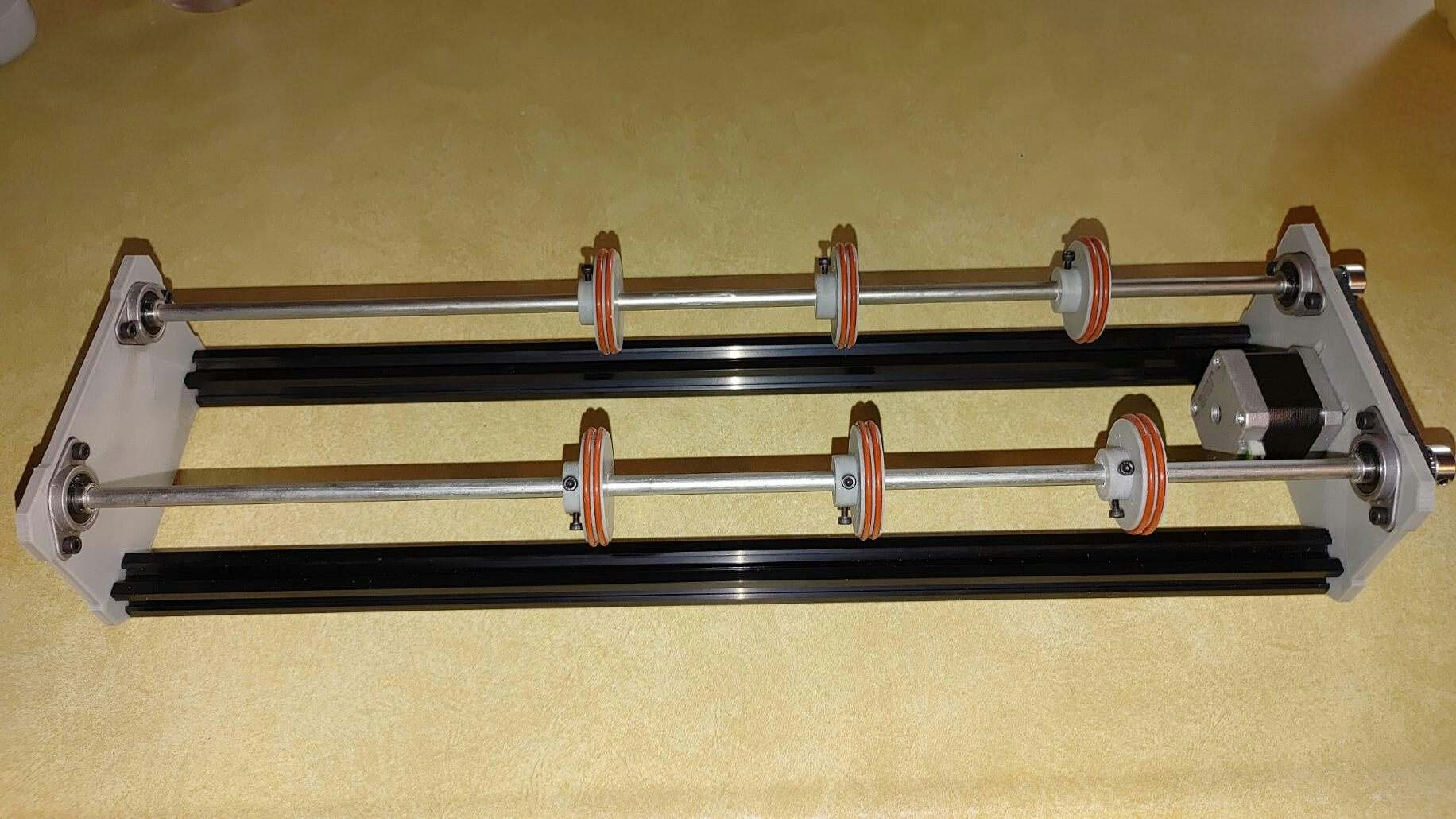
Wilfried, If you lookat this image which is the belt routing for the unit that I built, you will see that the ratio from the motor pulley to the rotary shaft pulleys is a 1:1 ratio. All 3 pulleys are 20 tooth GT2 pulleys. If you read through my original post it is not the roller diameter that I am concerned with. It is the milimeters per rotation. I would assume that that should equal the circumference of the larger rollers, but then in another part of lightburn I need to define the steps per mm for the GRBL controller. The two numbers relate to each other to calculate the proper rotation of the object that I am engraving on.
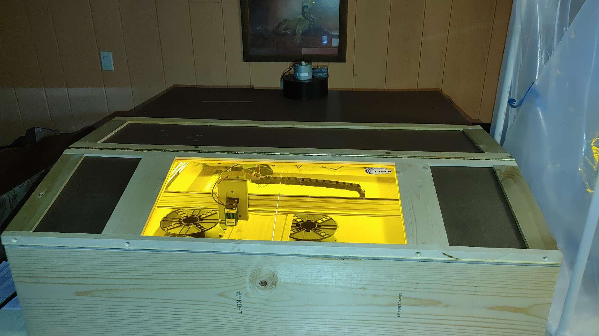
Willie, thanks, yeah the unit is in my basement that has that red and orange carpet which I guess is kind of a 70’s - 80’s feel to it. We have’t updaed that part of my house since we moved in.
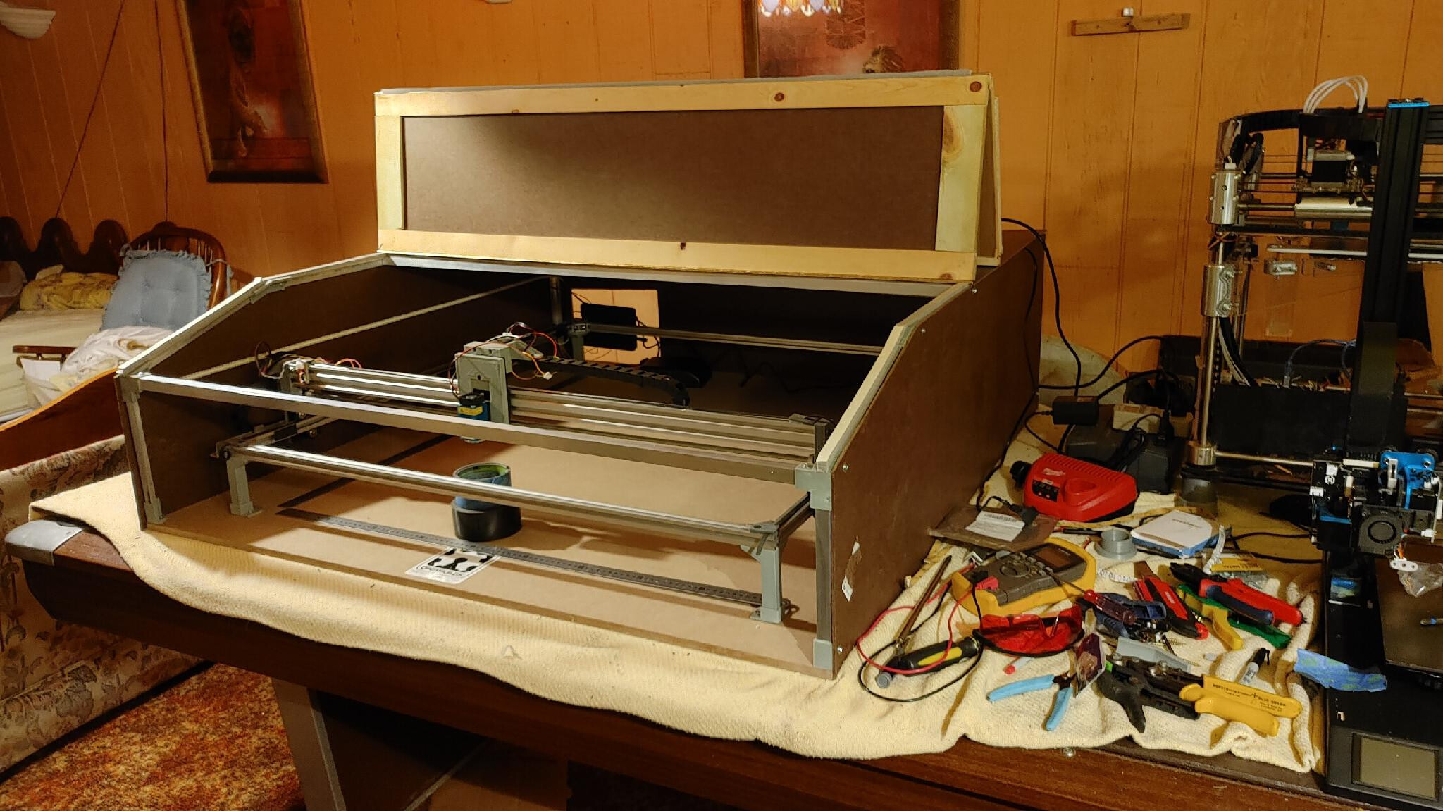
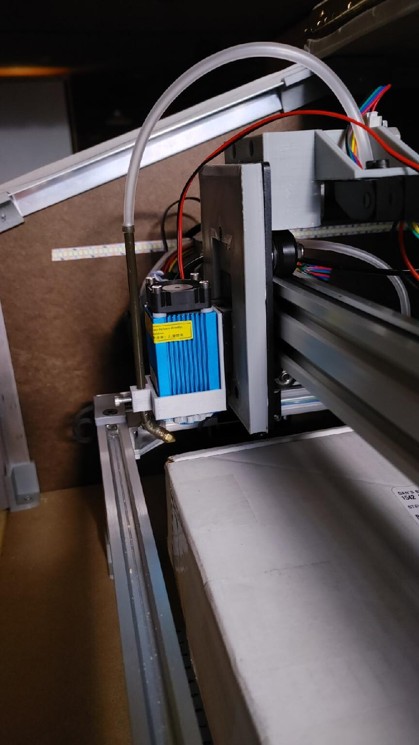
The build was fun and more to see if I could do it and make it work. I designed every part of the machine from scratch and 3D printed all the parts. The main rails are 2020 aluminum extrusions with the X axis being a 2040 extrusion. Someone suggested that I convert it to a CO2 laser instead of the diode laser that I am currently using. Some day I may do that, but for now I will use it as is.
It’s awesome, you should really get into it, get an old console tv and HiFi etc. The wood panels just make it perfect. Austin Powers would approve. YEAH BABY.
I dunno about converting it to Co2, the diode is going to be tough enough without mirrors etc. Nice work, I like the website too.
I don’t need mirrors for the diode laser, but I would if I used a CO2 tube. I would have to mount the CO2 tube on the back of the unit and direct the beam with mirrors like the other CO2 lasers do. It would just be a lot longer distance than what say a K40 would have.
Wilfried, Why would the pulley being 20 tooth have any bearing on this when the ratio of the motor shaft to the roller shafts is 1:1. I am also curious how you came up with those values? With the diameter of the wheels being 45.4, the circumference would be 45.4 x 3.1415926 (pi) = 142.628. The roller diameter would not be 1961.91, heck, the frame of the entire laser engraver is only 1 meter (1000 mm). Your numbers are WAY OFF…
So here is what I learned so that it may help others. And please correct me if I am wrong on any of this.
My setup: Arduino UNO with a CNC shield (see pic) that is running GRBL 1.1. I am using the X, Y and Z drivers. The rotary tool is connected to the Z axis driver and I don’t have any of the jumpers on for microstepping. The motor is a 200 step per rotation stepper.
So in Lightburn, go to edit > Machine settings and expand the last section. Scroll down to the options for the Z axis and you’ll edit the mm per step field. Here is my calculations:
Cr = circumference of the rollers (in mm) the object will sit on.
Mps = mm per step of travel
Dr = Diameter of the roller wheels
Pi = 3.1415926
Msr = Motor steps per revolution
Cr = Dr x Pi = 45.4 x 3.1415926 = 142.6283
mps = Msr / Cr = 200 / 142.6283 = 1.4022
Now on to the rotary setup options:
mm per rotation = Cr as calculated above
roller diameter = 45.400 (measured)
Object Diameter = 74.000 (measured)
Circumference = 232.478 (calculated by Lightburn)
Rotary Axis is set to Z Axis. I saw something that said that you have to play with the steps per mm value instead of calculating it to get it right. The calculation above says that that should be 1.402, but the piece still comes out squished a little bit. I will be tryng some new values to see if I can clear that up a bit.
You have a transmission from the pulleys to the roller shaft. 45.4 : 12.73mm = 3,56 as shown in the video.
You wrote:
“The roller diameter wouldn’t be 1961.91, hell, the frame of the entire laser engraver is only 1 meter (1000mm).”
Sorry my mistake. The Roller diameter is196.191.
This is equal, because you have a rotational movement.
I would prefer the y-axis.
Wilfried, I still can’t figure out how you are getting 196.191? Show your work on how you came up with that value.When the diameter of a wheel is 45.4mm, the circumference is 142.628, not 196.191. That part is simple math, You asked if I had tried your values, and no I didn’t because I knew that clearly your numbers were off when you initially told me that it was 1961.91. There was no point in me even trying that value. Read my last post where I show how I came up with my values. then if you feel that I am wrong, you can give me your explanation with formulas and numbers.