I have a situation where i need to simulate radius tools on cnc (4mm endmill) for sample cutting on a laser.
It’s a map, where there are thousands upon thousands of elements and i would need to add fillets to every one of them in the vector file to do this.
Any way to autogenerate paths as if laser beam/kerf is 4mm thick with radiused internal corners ?
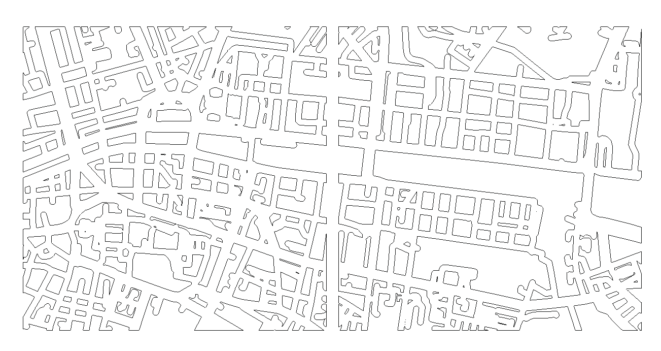
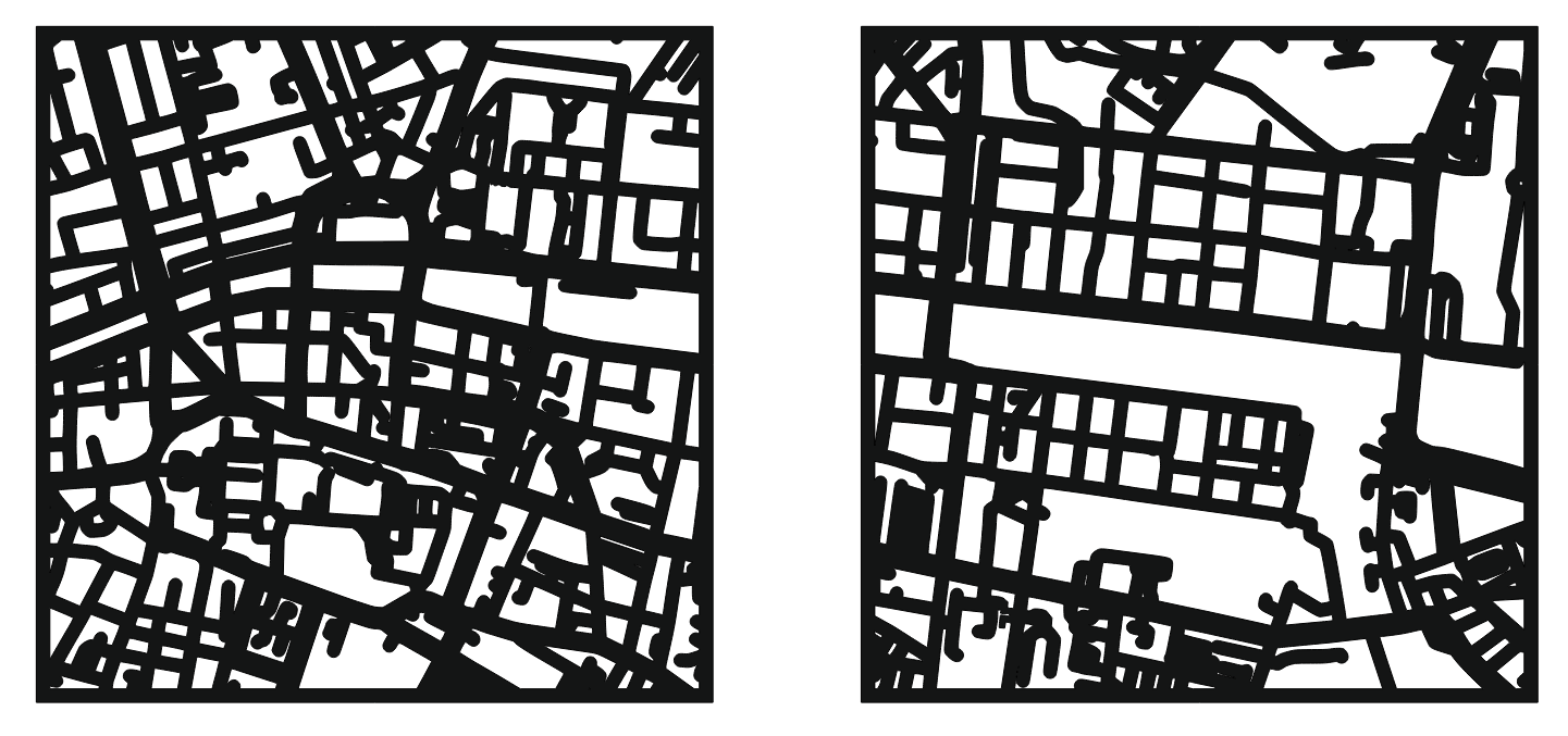
Pic below shows two 500x500mm squars i need to do as a sample for much bigger panel that will not fit my laser and will need cut with a cnc later on (actual cnc tests coming later). If i were to cut it as is it would have sharp corners of, well, laser cut (0.1-0.2mm ?) and not drop elements that 4mm bit wont fit.
All of what i’m doing here is an experiment trying to prototype things at home where i dont have access to a cnc. Finish panel will be much larger (about 1x3m 12mm thick panel).
Finding & fixing those may be somewhat less awful than what I suggested, but AFAICT the original image has enough oddities to stonker any automated approach.
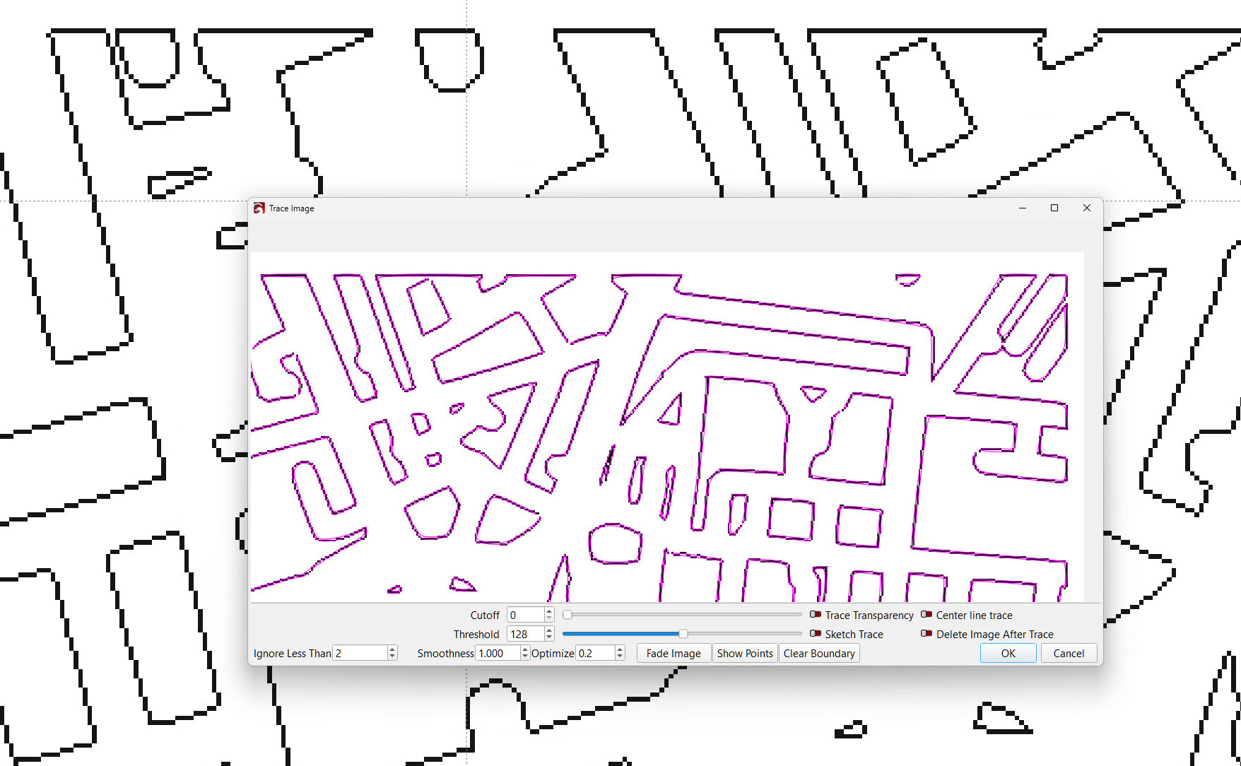
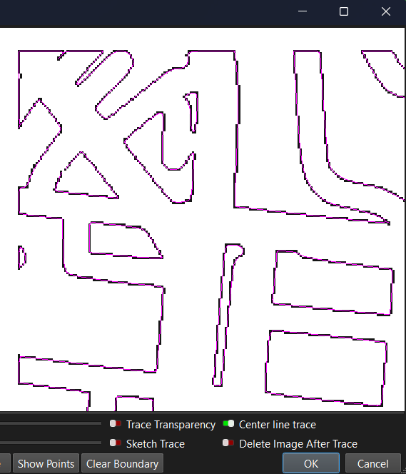
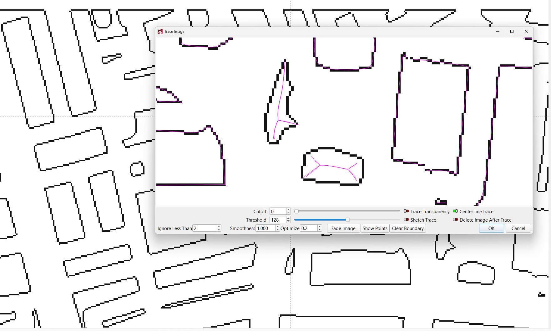
I wasn’t clear at the beginning - the graphics are already a vector, i just posted a screenshot from Coreldraw for illustration. No tracing is needed as such.
I cannot change anything in original vectors as i need to keep scale for tooling, so no ofsetting of any kind can be made. Using the same svg export for both laser and cnc. Cutting inside only, black stays, white falls out. All i need is to somehow fillet all the corners r2mm and discard anything what 4mm endmill wont fit into.
Not a problem: you modify the SVG layout in LightBurn to make it work for lasering, leaving the original SVG file unchanged.
Try this:
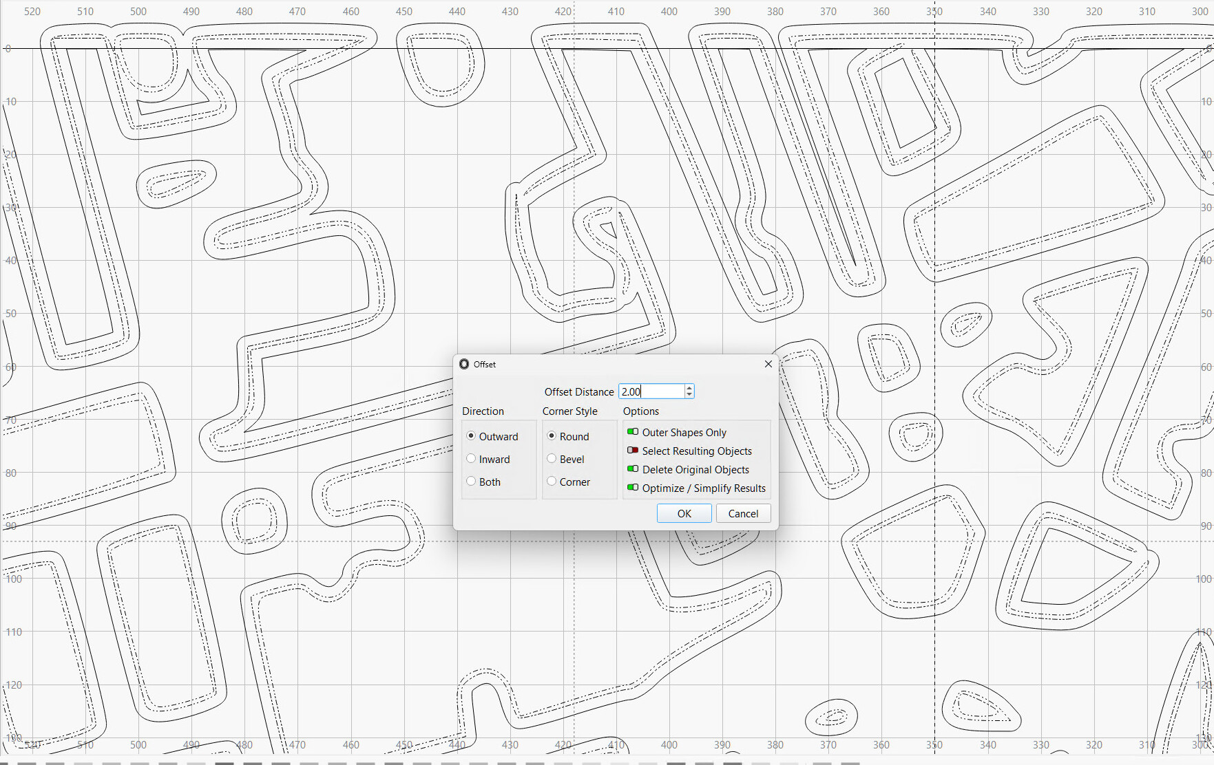
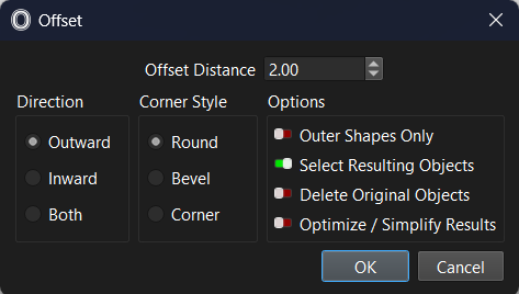
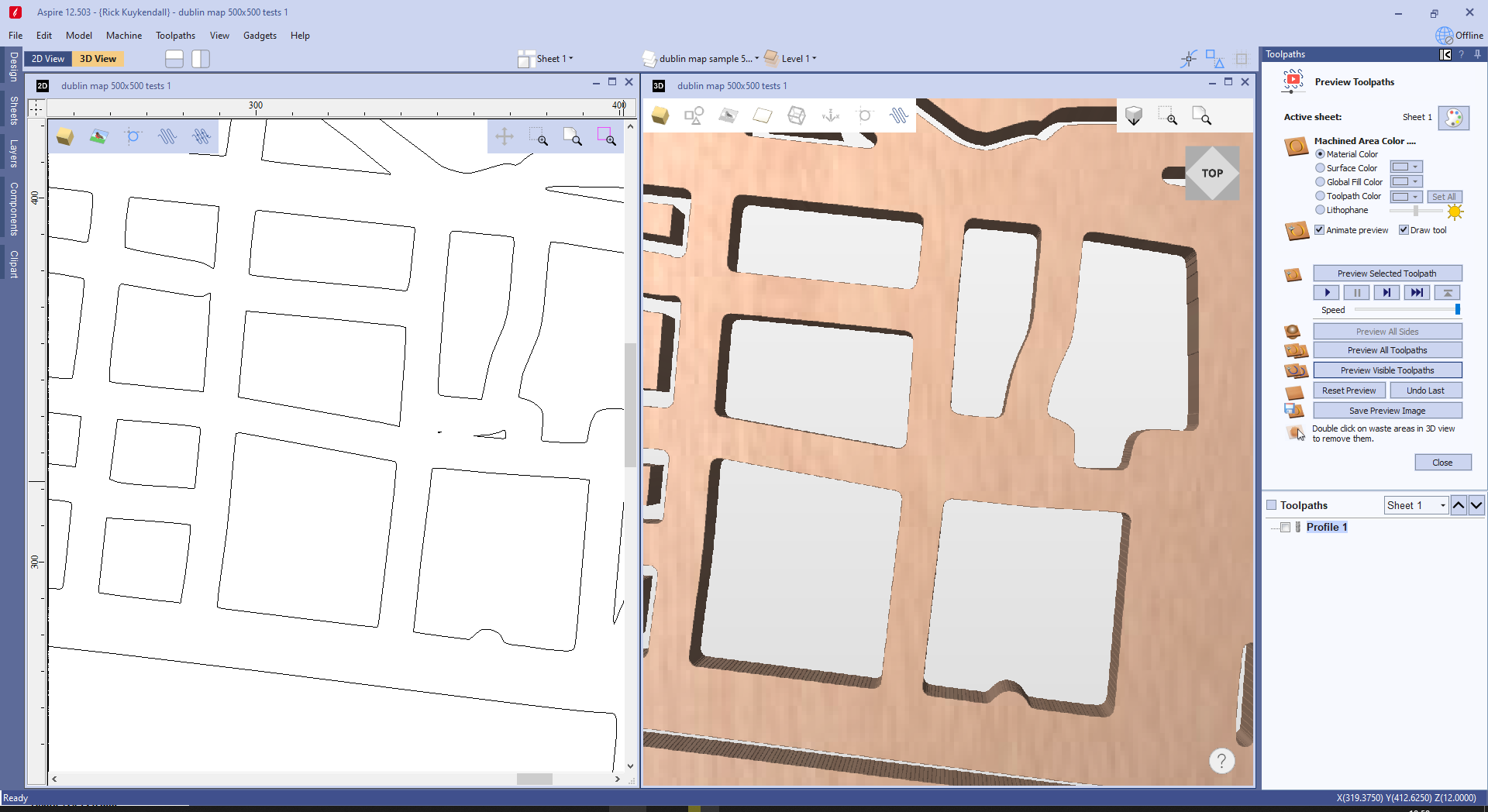
Apply a 2 mm Offset to the layer
Inward and Corner to get the cutter / spindle path
Delete original shapes
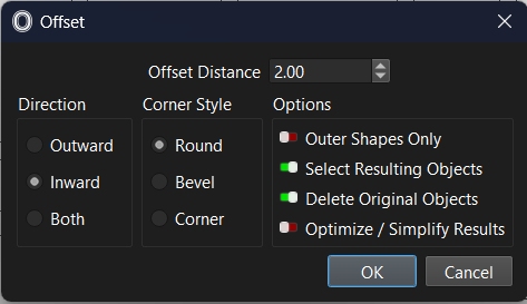
Apply a 2 mm Offset to the result
Outward and Round to simulate the cutter
Delete original shapes
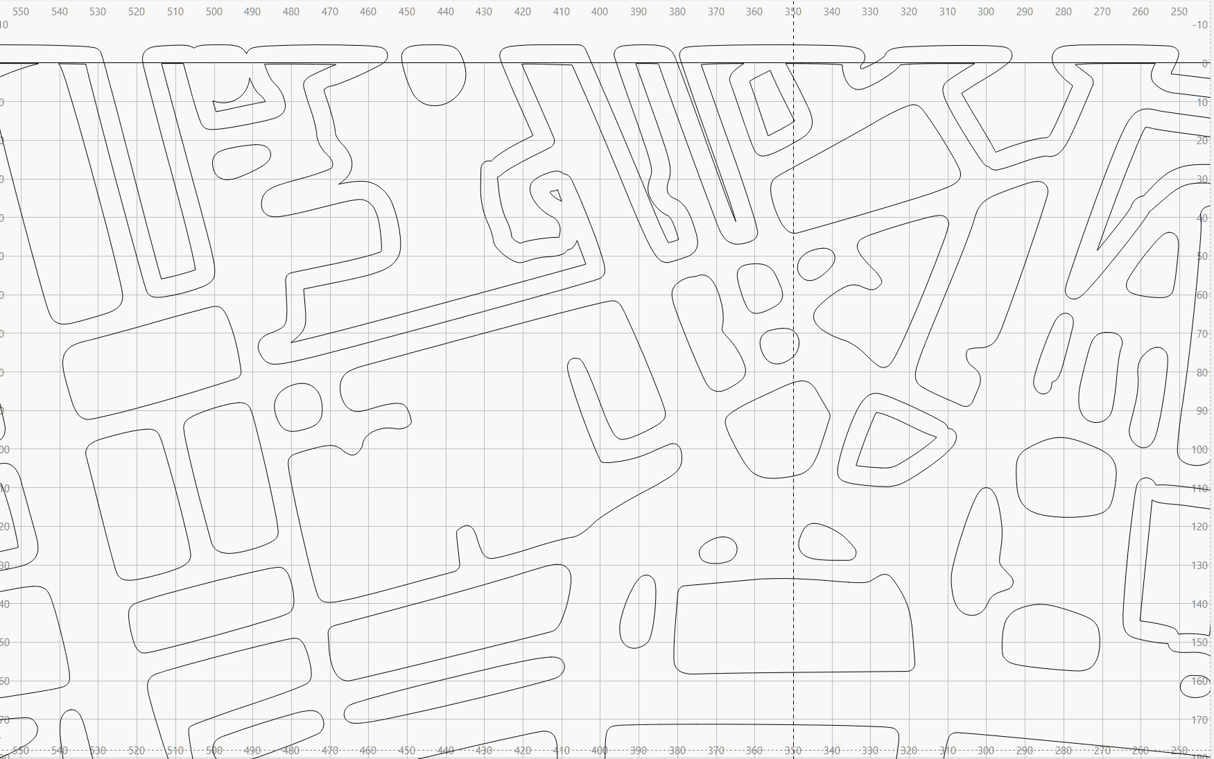
The result will look a lot like a 4 mm cutter run around the inside of the original shape. Very small shapes will have problems, but that’s just a preview of what the CNC cutter will do.
That was the whole idea, to simulate what it would look like if cut with 4mm endmill, but also losing any detail that 4mm endmill wouldnt fit into. Perfect.
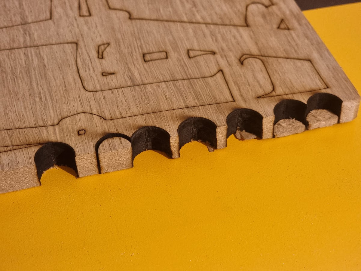
Also, the whole experiment is now moot as apparently cutting 13mm veneered mdf is a bit too much for 100w co3 laser 5mmps at 24mA in one pass -4mm focus, +0.25s dwelltime on start - FIRE Well there was no fire on tests, but i will not risk it…It kind of cut through but barely. Also one 500x500 panel would take an hour to cut… Might redo this experiment if customer agrees to go to 9mm which i cut before.
This is likely below the controller’s Start Speed, so it will reduce the power to the layer’s Min setting. Depending on all those settings, the machine may be producing well under the power you expect.
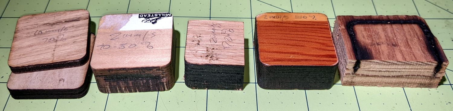
A few years ago, I knocked the Start Speed down to 2 mm/s and watched a 60 W laser having trouble with various woods over maybe 6 mm:
Your veneered MDF may combine the worst of both worlds: an interior full of random chemicals and a textured exterior perfectly holding the soot.
Well, i was watching BOTH (digital and analogue) meters show 24mA while test cutting, so i’d say its 100% limit for this tube (EFR F4, 100w sustained, 1.4m long). Actually tried 2 pass cut which made it worse for soot and made me worried of setting things on fire. Tried one pass at 4.5mmps, probably slowest i ever went…nope…
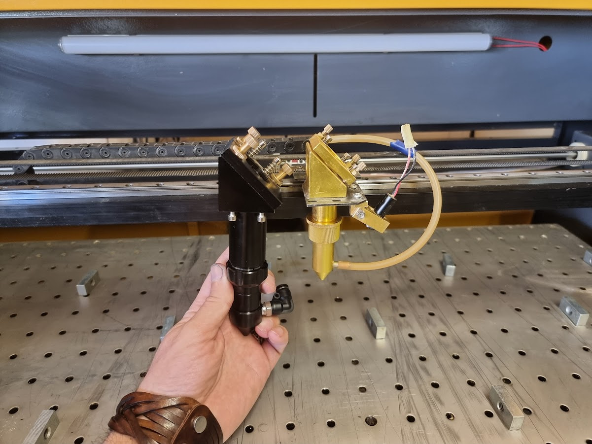
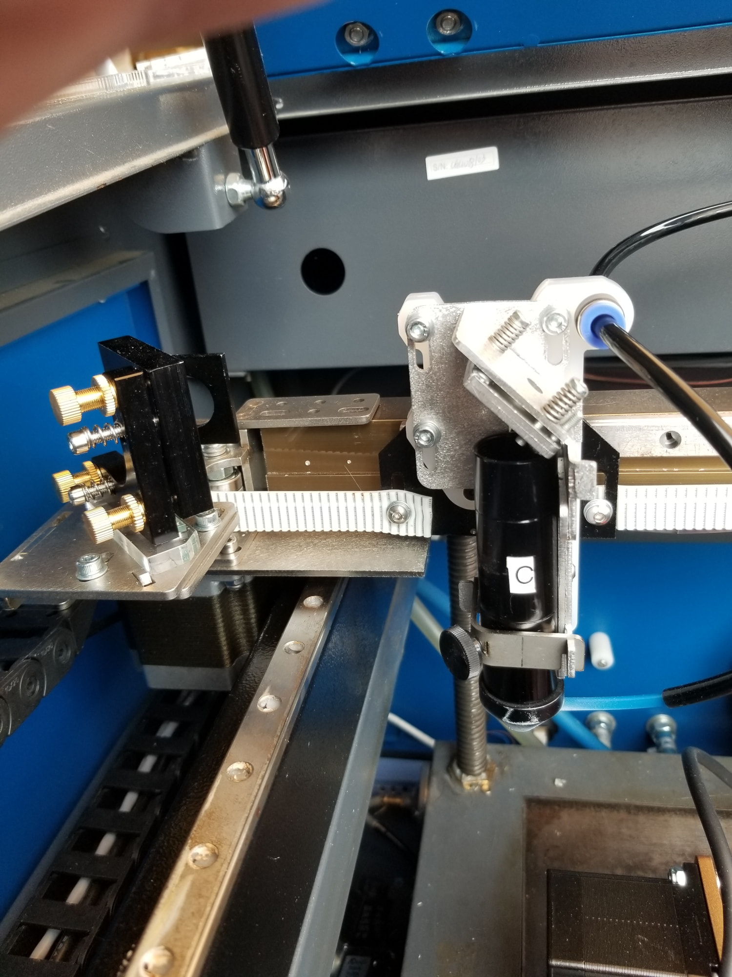
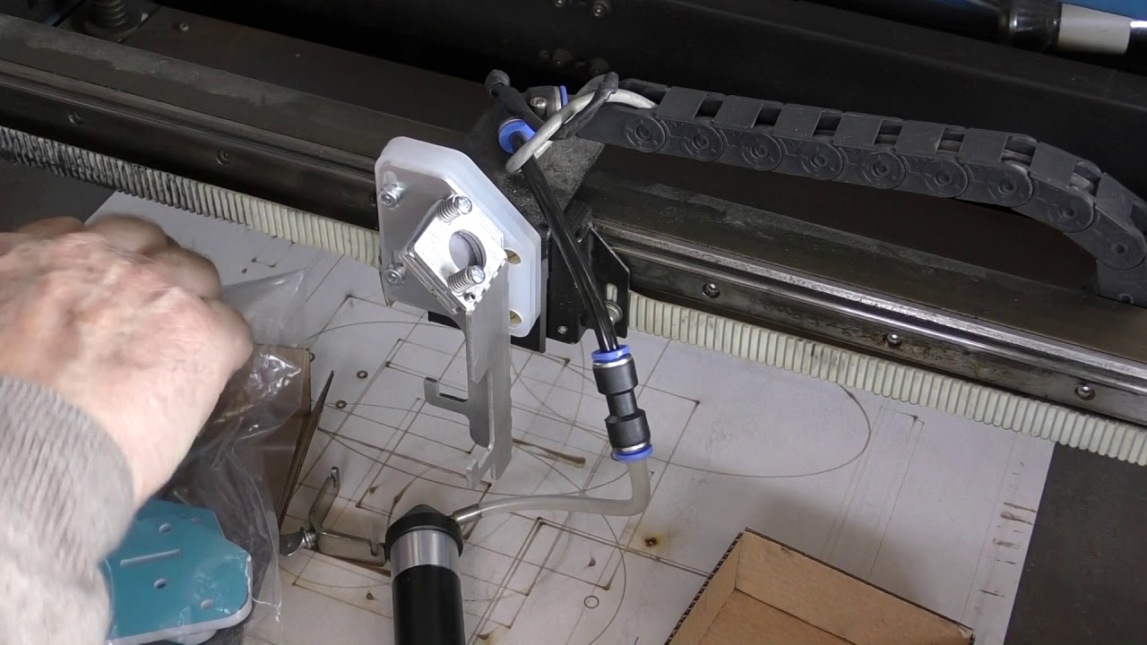
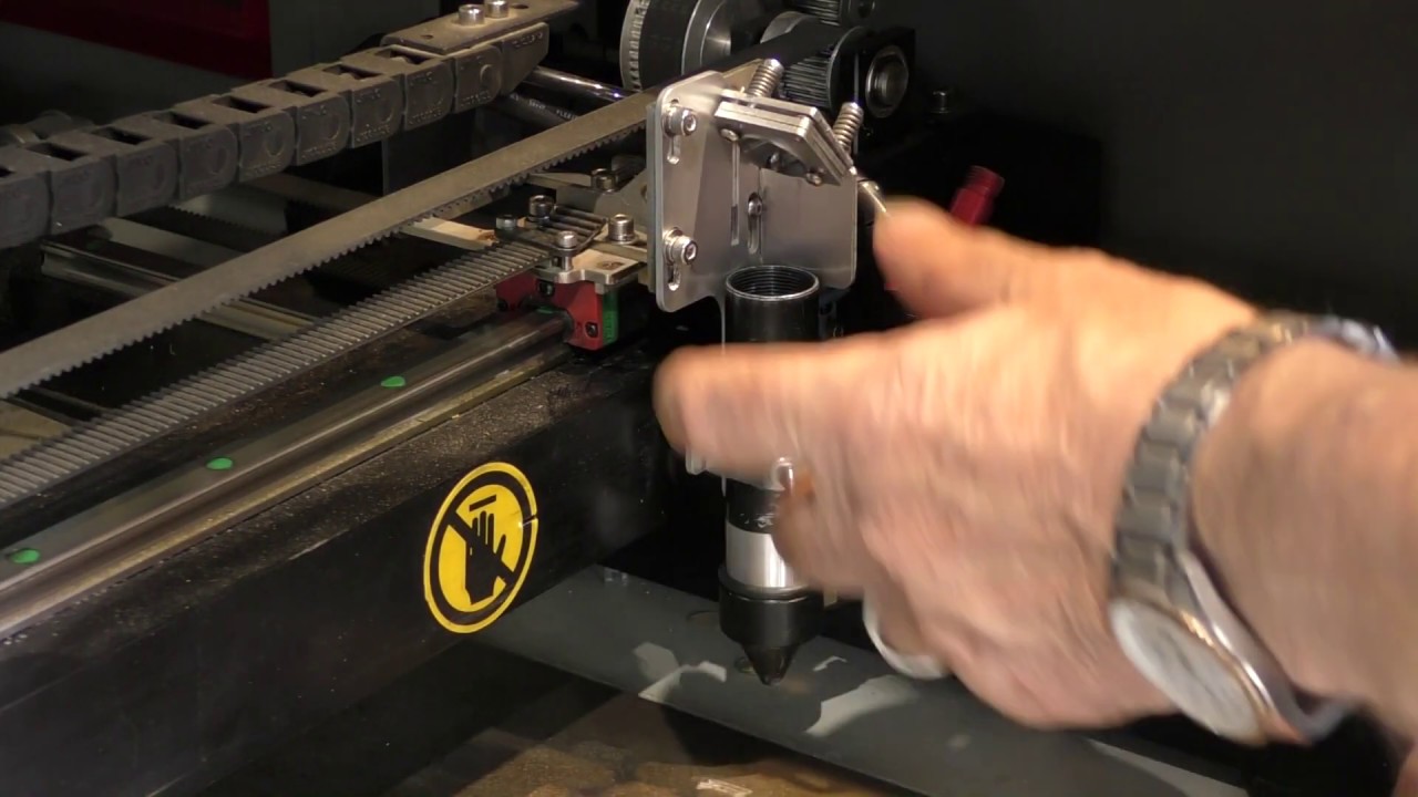
Focus is an issue as this is 2.5" lens i believe. I can cut 10mm acrylic fairly well with focus way down, but mdf just too much thermal damage for this thick of a material. I wish i could find a cone for 4mm lens for this head with no luck. Yellow one still on machine. Got the black one but might pose rigidity problems for its weight and rubbish gantry engineering (skinny gantry, skinny belts, direct drive nema17 motor, big head is a no).
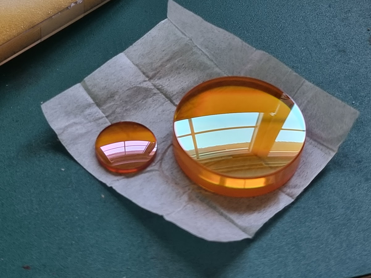
I also have 9" lens off of old industrial multi-kilowatt class laser, may fit it for giggles at some point just to see (left 18mm 2.5FL, right II-VI 9.5FL)