Speed limit for Lightburn? Trying to run @ 24,000mm/m - 400mm/s

Ed,

Appologies I thought that was how the file was supposed to work. I used the file as it came, it was setup for 24000mm/m on the middle part and setup to create the lines at 600mm/m. I thought that was sus in a good way so I left as is… Should I change the 600mm/m to 24000mm/m as well? It created the single vertical lines in a vertical fashion sometimes skipping one then going back to fill in. Should I change both layers to fill at same time to achieve what you looking for? Seems like you want it to scan the entire pattern.

I do not have a red dot laser pointer, so I used the laser beam itself. At first I tried without the red cover but the beam is WAY bright and nothing but a blue light takes over the whole video (2500mm/s2 acceleration, 24000mm/m2 Test - YouTube). Maybe I can increase the room brightness? The red cover seemed to block most blue light so the camera could get much better shot.

I will go buy a laser pointer, so this test can be completed. Anything specific you suggest? I would rather not reinvent the wheel as it seems your highly familar with this. Also I do not want to deviate from what has already been done since that could invalidate the test itself.

GRBL is setup for 1500hz right now but one thing I learned from this, is the setting you enter means nothing. So how do we know its running at 1500hz if we cannot trust any setting thats entered? Also I dont see a setting for PWM percentage.

The video was shot at 60fps on iphone, I have gone back and confirmed in the file information settings.

Where do you get that base number 7200mm/m?

Okay I will share the settings, but seems like I need to align the stars first to get there. I did not realize this was such a journey lol. Suprised there isnt a some kind of handheld tachometer to get since It sounds like I need to purchase some extra stuff to complete this. Or maybe if the GRBL code reported time and X,Y position so we could math it out and figure the speed that way.

Sorry for all the questions, still trying to understand this the best I can. And obviously to see this to the end… I cant imagine how slow these machines are stock ← Everyone must think they are running 6,000mm/m but really its like 500mm/m… rofl

I thought pastebin was for text files, Im on the site now but can only find a spot for text. No video upload from what I see.

if you are looking to measure speed of the laser head via video why not turn the diode laser power way down? Diode lasers do not need a red-dot laser pointer to aim since they operate in the visible light spectrum so just turn down the power until it turns off then increase it one percentage point to turn it back on at its minimum power level.

LightBurn already has this feature builtin…

Also, if you’ve not figured it out, the firmware on the laser controller board has builtin limits for the machine. If you are not using factory supplied firmware then YOU are responsible for setting those values and those will be the limits no matter what you set in LightBurn. ex. anyone can ask a child to run a 7 minute mile but he/she can’t do it since they have builtin limits. :wink:

Since I commented at the beginning, I’ve followed this… The supposed maximum according to @misken is around 200mm/s after fine tuning…

@DougL is absolutely correct, about controller limits… and I’d ask to see your configuration following up on his suggestion.

I’ve messed around with this a bit on both the cnc3018 types and my OMTech China Blue.

The co2 currently has an acceleration value of 45,000mm/s^2. It will run 1650mm/s.

IMHO, it’s another one of the 99% or more that comes back to an incorrect configuration.

Acceleration values themselves are useless without an associated target speed.

Good luck… maybe you’ve got something there :wink:

:smile_cat:

Here is my current controller configuration.

config.txt (3.3 KB)

Lightburn doesnt contain any settings besides the layer I have set @ 24,000mm/m

I set it up with parameters for my laser, because that’s where I ran it. You get to configure it for your laser, with suitable parameters.

For example, I used Dot Mode to draw the millimeter scales, because my laser will burn chipboard at the lowest power and fastest speeds. The central engraved block also uses low power, because I could record the motion using the red dot pointer.

Your situation will be different, so adjust as needed.

Start with low scanning speeds to verify your measurement technique. When you can measure lower speeds and get good agreement with the preset layer speed, then increase the speeds beyond what anyone else would use.

Showing a succession of measurements that demonstrate you’re in control of the action would be persuasive.

Well, that gets into measurements using an oscilloscope, which is very much not something I’m going to lead you into if you’re not already in that field.

I’ve done it and it works well:

The point of not using the main laser at reduced PWM to avoid flicker is why I think a red dot pointer will work better: it’s always on with no modulation.

I assumed a frame rate of 30 frame/sec (not the 60 you actually used), which means each frame lasts 33 ms. Assuming the shutter stays open for the full 33 ms and the white blur in your photo is 4 mm long, then multiply them together:

7200 mm/min = 120 mm/s = 4 mm / 0.033 s

Double that for 60 frame/s, but there are enough other assumptions that I don’t believe the answer means anything, other than to rule out the speeds you’re claiming.

Well, that’s why you’re getting a lot of pushback on your claims: if you haven’t actually measured the results and can substantiate what you’re saying, then they’re just words.

Although this topic is kinda interesting, I really can’t afford the time right now to get you up to speed on mmmmm measuring actual speeds. I think you’ve got enough to work with already, so make a lot of measurements, cross-check the results, fix the inevitable errors, cross-check again and again, then present what you’ve found.

The G-Code simply contains the values you specify. The GRBL controller caps those values to the actual machine limits, as specified by its configuration.

Absent the machine’s GRBL configuration, pretty nearly nobody will be believe anything else.

That’s just the first step of demonstrating your claims.

Then you must show that you can measure the actual results in a dependable way.

Good catch.

Use https://imagebin.ca/ for binaries. It has a 15 MB file size limit and requires a Twitter account to use advanced features, but perhaps you can find something similar for larger files. You won’t need to upload the video if you extract single images from the original video and present them with good data.

Yes thank you for our time. I’m still shocked by how everyone does the speed test entirely wrong.

Really thought there would be a standard file that was already run on a few machines to calibrate and confirm speeds, then everyone could use the file and compare their finish times. I realize this would be a generalization of the acceleration and speed but this all seems a bit insane to my girlfriend who watches me pull my hair out trying for internet clout.

The machine physically sounds like its flying, my job times have been cut down, I learned another thing or twelve and I’m happy.

Go ahead and close this, no reason to prove my position when we all need to get back to work!

1 Like

I think you have a misunderstanding what acceleration is. It’s the difference of speed within a time frame. 2500mm/s² has nothing to do with 150,000mm/m² that’s not the same. It’s the difference of 0mm/s to 2500mm/s within 1 second. I can’t explain this very good in english, refer to the physics pages :slight_smile:

The stock acceleration of all Sculpfun lasers is 1000mm/s². Also on your device. The 500 are coming from my recommendation, because people with simple mechanics without linear rails had problems with vibrations. I should change the wiki to reflect that 1000 is fine for all machines starting from S10. People that used speeds up to 12,000mm/min with a Sculpfun device also used accelerations up to 8000mm/s². That’s no problem. There is just a physical limit, where the hardware won’t follow the command anymore. I don’t think the hardware is capable of 8000mm/s² to be honest. 2500 like in your case is totally fine.

I repeat myself, you can command it at those speeds, but it won’t run at those speeds.

No. That’s what the others are trying to explain. The 1500 Hz means exactly 1500 Hz, but only if the hardware can follow the software. If your parameters don’t fit, the software falls short at one end. It either just does something undefined or is trying to calculate the maximum that is possible.

Again a no (and a yes :slight_smile: . Yes, diode laser ARE slow. People know that and are fine with that. As I said, if you want to have more speed, choose a CO2 and you are in a different world. People can run the laser at 6000 and it will do. The point is, if you are running faster, you are not automatically gaining more.

Great! I think it’s the same for us :slight_smile: We like being challenged and thinking deeper about the matter. And as I said on some occasions, if you manage to verify such speed settings or get a perfect set of parameters to reach that speeds - the community will be very happy to get them! Of course I will also list them in the wiki :slight_smile:

That’s a lot of work on older software and limits your range of testing to that many layers… there are better ways, such as the builtin materials test…

As he mentions you have to have some experience…

Have you visited this site?

https://www.o2creative.co.nz/laser/lightburn_basic_generator.php

You need to learn to develop these speeds/feeds yourself… it’s not that tough, you just need to understand how the laser effects the material…

As the Louisianan Guy points out, it takes some experience.

Good luck

:smile_cat:

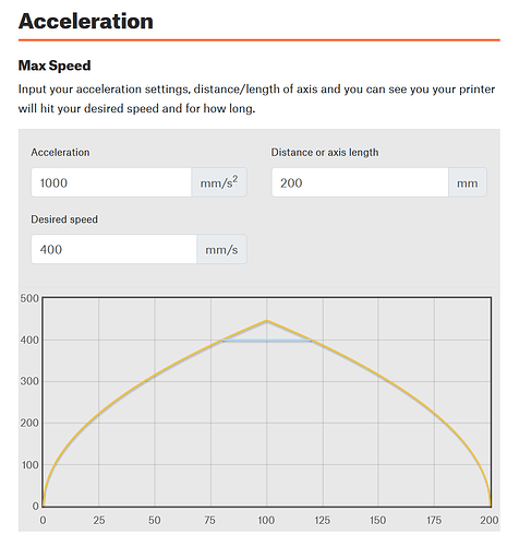
Maybe one last addition, there is a nice calculator at Prusa, where you can calculate if your system will really reach these speeds.
As you can see, at 24000mm/min with an acceleration of 1000mm/s², the laser will only reach that speed for a distance of 25mm (in case of a line of 200mm). The rest is acceleration and deceleration (and only in the case, the laser is physically able to reach the top speed).

But he “Louisianan Guy” is testing completely wrong if I’m to believe everything in this post. I don’t see him breaking down footage to measure the camera FPS and how long the beam width is.

He simply throws the speed settings in hits go. And then everyone says ahhh okay it must really going that fast. How can that be believed? I have done the same as the “Louisianan Guy” but everyone says naah thats not the right way.

So how is it okay for his speed tests but not mine. I don’t get the double standard. I would expect to see someone else measuring frames of footage like what is suggested here.

Speaking strictly for myself, I don’t have time to watch random videos and run an analysis for each one, so I tend to ignore all that stuff. There are far too many folks being wrong on the Internet for me to take any personal interest in debunking their claims.

You popped up in a place I happen to watch, making claims that flat out do not make sense. I’m willing to be convinced, but not by statements without evidence and careful measurements. Absent that, I’m willing to run an analysis once, so other folks don’t fall into the same trap.

Folks with the knowledge and equipment to verify their claims tend to make reasonable statements, although sometimes with surprising implications. When they speak, I listen: they may not be right, but we can evaluate their measurements, rather than their claims.

1 Like

When you understand that all of this comes down to putting energy on a spot and the fact that the energy is a function of the laser power output AND speed of the laser head it starts to sink in that you must find what YOUR machine can do and manipulate the power and speed for YOUR best results.

Every laser puts out different power levels and can run at different speeds although most are not trying to break any speed records and want repeatability without excessive machine wear nor machine vibrations.

Things that effect your laser power output:
Diode lasers:
The original designed specification, 3W, 5W, 7W, etc. 50% for one is different than 50% on another.
Factor in lens design and shape that’ll change how big your dots are and how when you put 50% power on a 1mm dot it’s far more power when that dot is 0.5mm.
And then there’s smoke on the lens and other debris which will impact power output along with the wear on the diode itself over time.

CO2 lasers:
Tubes are of different power levels, tubes wear and power output reduced.
Beam size changes with wear…
Lens and mirrors can get dirty.
Mirrors get out of alignment.

Don’t even get me started on the different wood reflectivity, density, composition.
For Norton While Tile Method(NWTM) you have the variations in paint and application thickness.

So people share their design files and you go in and tweak them and find your sweet spot.

I’m not a complete imbecile. I understand that different lasers, speeds, power outputs, materials, humidity in the air, all require different settings and vise versa.

What I was trying to get to the bottom of. Was that when I set my laser in GRBL and in Lightburn for a speed of 24,000. How can I prove that? Not even talking about engraving at this point.

I don’t care whether it’s actually engraving or not because once I prove it’s running at max speed I can dial it back.

Just like my car says it’s doing 55, I can pull out a gps and verify it’s actually 55. That’s all I’m trying to do here.

Machine and settings say 24,000 so just trying to verify this in real life, since many say not possible. I would like to verify myself. Trust but verify.

If you’re happy and content, then don’t worry about it… This will only really matter if you move to a different machine where this could be a problem…

Many of us have been around these and know they have limited speed… the co2 machines are usually limited to around the 350 to 500mm/s range… They are faster than the any of the smaller machines for a number of reasons.

It may very well run at that speed … technology changes, as do materials…

I think most of them wanted proof that it actually did run that fast considering it has to slow down, change directions and speed by up with an image, just a line it still needs to speed up and have room to slow down…

We have all seen claims from these that just can’t be met in reality… Doesn’t mean yours are not, we’ve seen too many go by that it isn’t true…

Hang in there …

:smile_cat:

Lately, I’ve seen some videos of him that were designed horrible and questionable. So far, I regarded him as one of the great experts in this field, but there were a few mistakes he made that a school kid wouldn’t. So, I can easily imagine that you are completely right here, he could be entirely wrong in what he did/does (don’t know the actual video you are talking about).

just draw a spiral or other shape with a length of 24000 mm… start the program and see if it does it in one minute… after this you will be convinced that the machine is NOT running at that speed :slight_smile:
from the video i saw the machine is running at about 400-500 mm/m (educated guess after 30 years of professional experience with CNC machines)

If it’s cornering, it might not be able to maintain the specified speed… not to mention you want them to engrave a 24 meter line (over 78 feet) to time it?

How about 1/2 the length for 1/2 the time or 1/4 length for 1/4 time…

None of this will give you the true X maximum speed values…

@ednisley solution is the most common and dependable…


If it’s not going straight, then you have to take into consideration that both axes are involved…

The Y axes has to carry the total X axes mass, along with it’s own mass from the Y gantry and associated drag chain, wiring and air. This forces the Y axes to be inherently more sluggish to respond.

Generally, machines have a lower maximum speed and acceleration value for the Y axes… mine certainly does.


I think it’s been solved anyway…

:smile_cat:

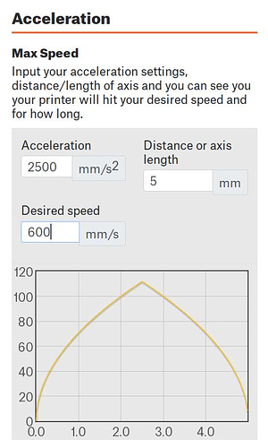
The Prusa calculator shows how much distance is required to get up to speed, then back down to a stop, along an isolated straight line. The set of videos above show rubber-band framing a circle, so the actual path is a series of straight lines circumscribing the circle. Guessing the lines are 5 mm long, the speed along each line with a commanded speed of 24000 mm/s and an acceleration of 2500 mm/s²:

That’s pessimistic, because the hardware can handle obtuse corners without coming to a complete stop, but it’s a reasonable approximation.

The average speed might be 60 mm/s along the line, 10% of the commanded 24000 mm/s.

The line must be 150 mm long before the hardware reaches the commanded speed. The average speed along that path will still be considerably less.

Gotta bookmark that calculator for the next time in this rodeo …

Edit: One can peruse the GRBL source code to find out how it works. How much of that made it into the various forks / ripped versions remains a mystery.

i was just trying to point out that F24000 is not a realistic expectation … anyway at that speed the laser will not have time to mark anything :slight_smile: I do work with CNC machines that reach F20000, but only on rapid traverse, and they cost about £1.000.000 :slight_smile: