I’m using a Vevor 80w Co drived based on Ruida.
I’m also using a rotary from Vevor but when I use it, graphics are about 4 times wider thant it supposed to be.
I tried to burn a square 1x1cm then I got a rectangle 1x4cm.
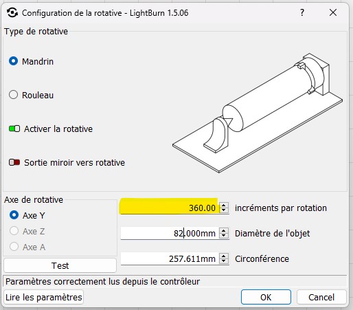
I tried many values in the yellowed settings on this image. I though it will change the size of the rectangle until I reach a good result but the issue is still the same.
whatever if I increase or decrease the value, I have exactly 1x4 rectangle until I go to 369.99 but at 370 then it’s burned on one single line.
I tried to find as much details on the axis and these are all the settings I can get
The only way I found for the moment is to multiply my graphics by 0.4 before burning but it doesn’t work on every texts… Sometimes it’s ok, sometime the texte is squeezed.
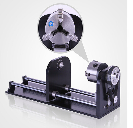
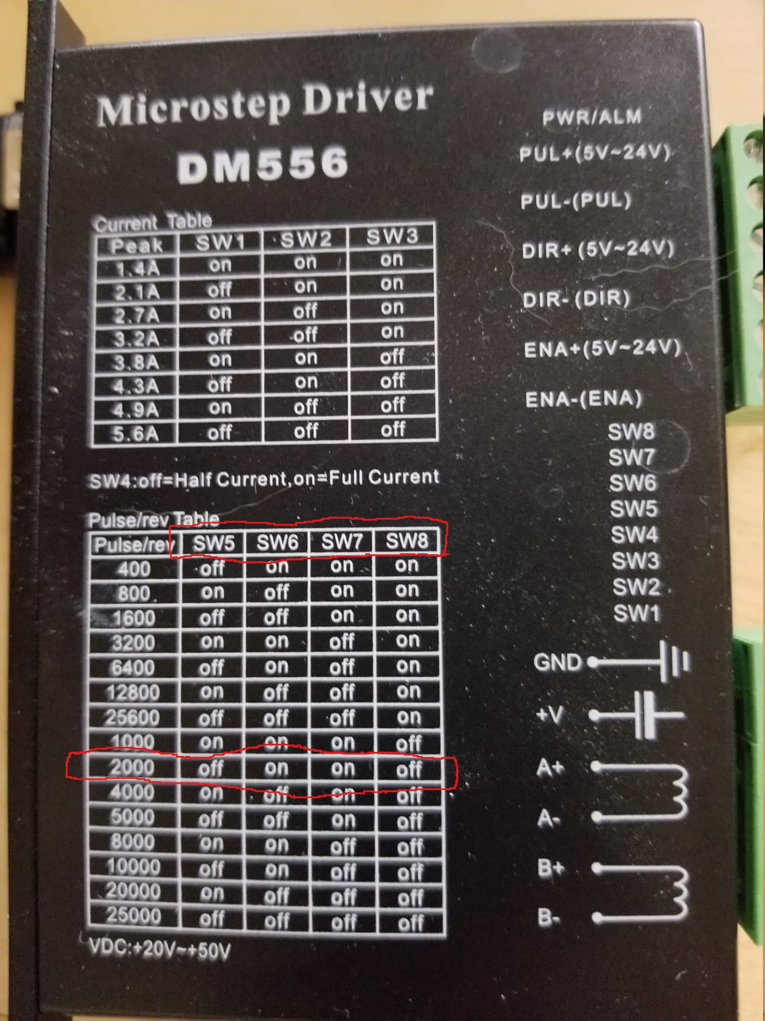
It looks like you have a belt drive ratio also to contend with. Set your switches to 3200, or 6400 for example and then set LB for that same setting multiplied by belt drive ratio, looks like 4:1 so example microstep driver dips set to 3200, belt drive 4:1, 3200X4=12800 LB setting.
You are correct about the 1.8 degree per step on your motor, but that is why we use the microstep driver to reduce that to the settings on the table.
Hello, it seems that in your configuration you have configured 5000 pulses per revolution. Check carefully which one is correct for your engine, and then you must multiply by the ratio with the belt, which in your case seems to be as they told you, 4:1
So that you have an idea, I’ll tell you my experience and my configuration:
To find the corrective pulses for the motor, I changed and moved manually to both sides in short and long stretches, and I noticed that in the “wrong” settings it made noise and the motor seemed to jam. With this I reached that my pulses per revolution configuration was 6400 (I repeat, in my case with another engine)
And my ratio is 3:1 so I multiplied 6400x3=19200. I set that value and after doing some tests I made a fine adjustment to 19270
If your pulse value really is 400, you should set 400x4=1200 and then try and adjust as necessary.
But if your configuration is 5000 it would be 20000
Try to use the configuration with more pulses per revolution that your engine supports, you will have more precision.
PS: I’m using Google Translator, in case I don’t sound too human haha
To do a test you must put the exact diameter value of your object in the configuration, and copy the result established in the last circumference field. And you draw a rectangle where the height measurement has to be that circumference result, and you make the marking.
You will have to verify that the start line of the rectangle coincides exactly with the end line, that they overlap. And there you adjust the value so that it matches exactly, but always based on the calculations that I mentioned in the previous post.
That works for an even number of teeth when the tooth tips are on the pitch diameter, but the latter is rarely true.
Counting the teeth gives the exact ratio, although I admit to marking the starting tooth and maybe every tenth tooth after that, then counting a few more times than seems strictly necessary …
Ha! True, but close enough to tell if you are 2.5:1, 3:1, 4:1, or 6:1. Probably not going to get an “off the shelf” tooth and belt rotary at 3.8857:1 so probably safe.
Now if I assembled one out of spare parts…
You should put the switches on your stepper drivers back to wherever they were before you started changing them.
The settings everybody is talking about are in Lightburn. I’m not a rotary guy, but I believe you need to enter the number of steps it takes to turn the chuck one revolution.
I posted a link that advised you how to set this up…
There is nothing in that link about changing the switch settings … why are you?
These are used by house wives, students, dummies and they plug them in, no hardware changes, and set them up, they work… If it was this complex, I don’t think anyone would have them.
IMHO, the problem here is you are making something simple, much more complex than it needs to be. If you followed the working procedure and it failed, please let me know as I have many links to the post and I need to fix it if it has a problem.
You have DM542 motor drivers and I have a DM556 they many not have the same switch settings… did you check?
This should have worked after my post 4 days ago, I’ve kept my mouth shut, but I hate to see it go on ad infinitum.