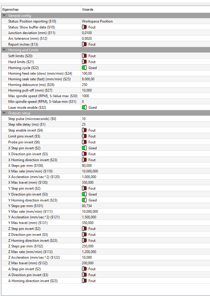
I just followed the updated guide on adding limit switches to the TwoTrees GRBL laser.
But it’s spitting out a few error since i have been tinkering with it before. (2 pin wires instead of the 3 pin wires it actually needed)
When the laser boots, it asks me to unlock it via this menu:
Grbl 1.1f [‘$’ for help]
[MSG:‘$H’|‘$X’ to unlock]
[MSG:Caution: Unlocked]
When i do $H (i think it means Home and X just unlock)
You do hear the steppers turn on and lock into place. While it’s happening you aren’t able to move the gantry, but neither does the laser head move.
After it’s been thinking it has tried to home it spews out the error:
ALARM 9: Homing Failed, Could not find limit switch within range.
A link is always nice, so we can ‘follow’ and see how you did this…
It’s a good idea to re-read these and try and make them more clear for us…
It sounds like it requires a three wire connection and you only used two of the three and it doesn’t work…?
I’m hoping I know what you mean …
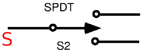
What type of switches are you using, NO | NC?
How are they wired.?
If you start the machine, does the head/carriage move towards the limit switches?
At one place you say no, but I’m not sure on the boot.
If they don’t move you need to check the type of switches and their connections to the controller.
From the little information, I’d say the machine is detecting the limits as active (when they are not) and can’t ‘back off’ them within the specified distance. Using a NC switch when it’s expecting a NO…?
I used the video from the official LB Youtube channel. The switches are 3 pin, but came with 2 pin cables.
There is a point in the video where he clicks home, but that’s where my laser does nothing.
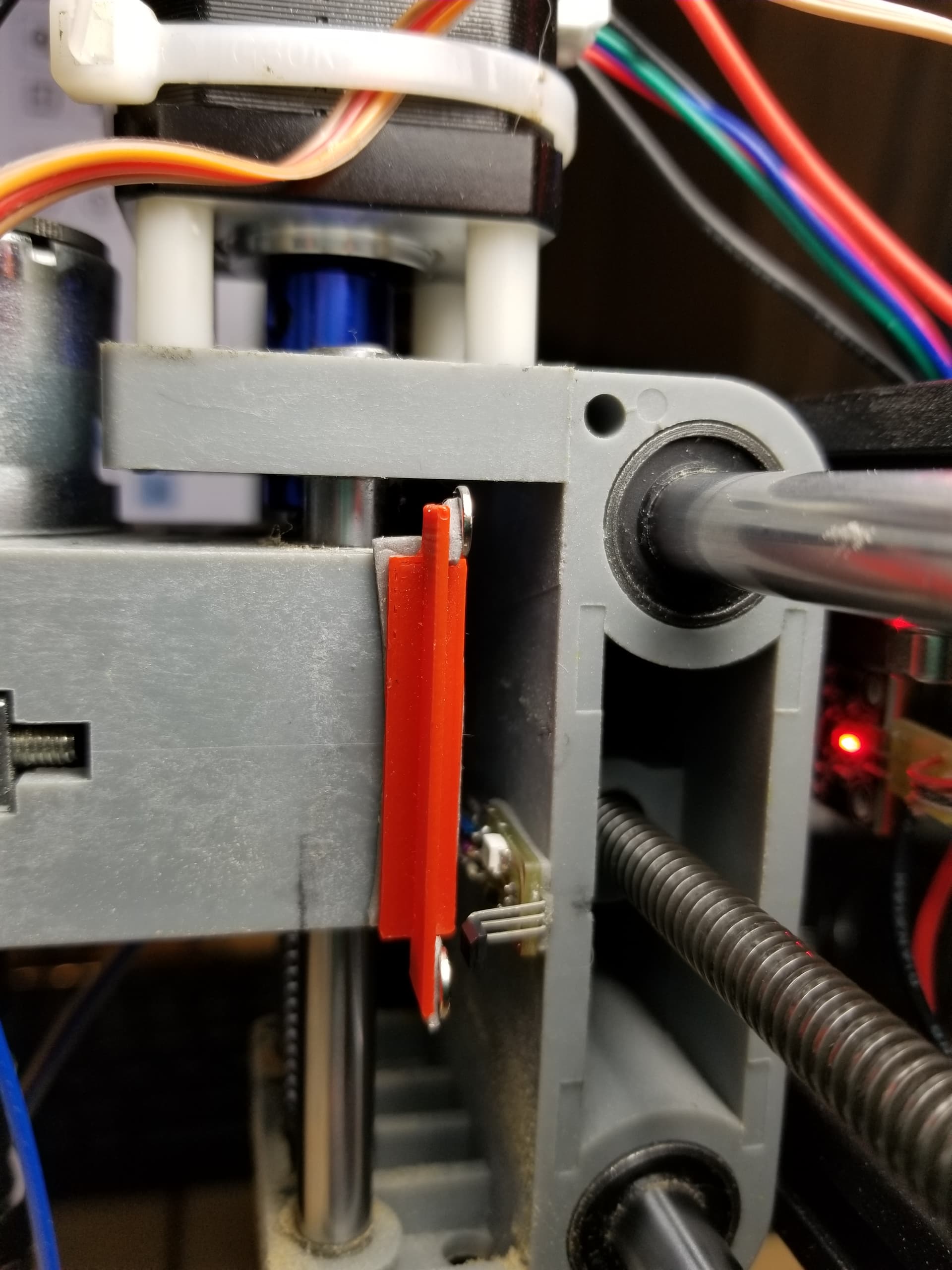
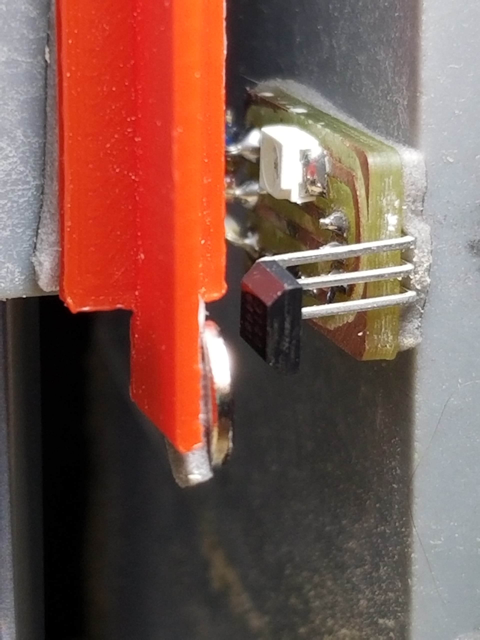
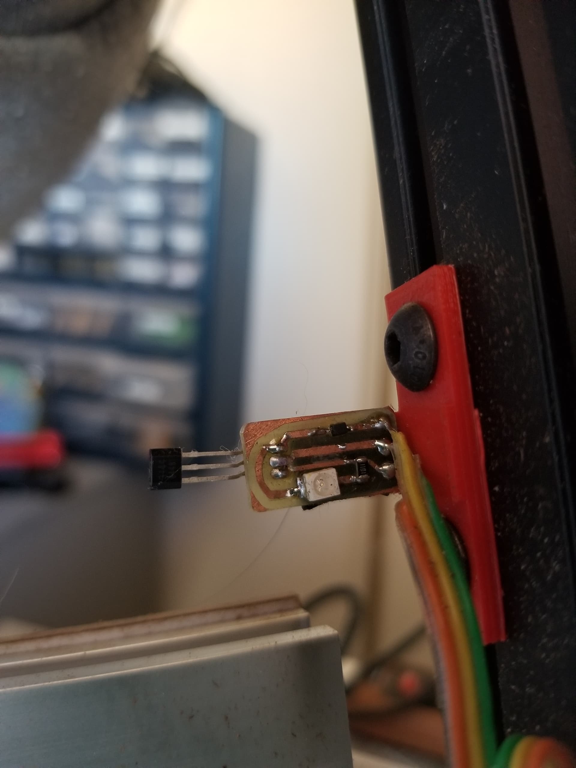
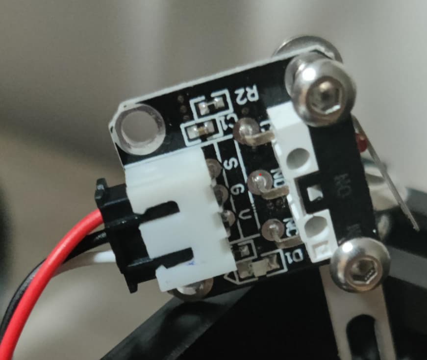
I now have the required 3 pin cable. when i push the pin it lights up a LED so you see if it’s triggered.
Nevertheless it’s set up for no or nc operation, and I wanted to know which he had chosen. It just pulls it up or down. Nothing to do with hall effect… it’s just a mechanical switch.
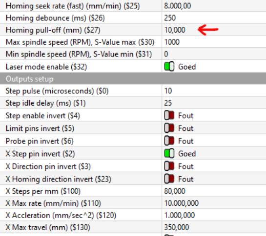
If you wish to pull it down use the G, if up use V.
Jack, I know this is off topic, but please understand I am not trying to challenge you. Like you, I am just trying to help someone reach a solution. I have seen your replies MANY times and consider you to be an SME (Subject Matter Expert).
I just chose to look at it as Signal, Ground and Voltage. It matters not if you pull it to ground with a metal sliver or via a mosfet, it gets pulled to ground and the controller reads it as active.
Use the V pin if you want to pull it high…
The basic configuration is to pull it low, so the Signal wire goes to the controller and the side that ‘makes’ on contact (NO) goes to ground. It might be labeled V, but it’s just a switch.
The switch is labeled C, NO, NC. A NO switch makes contact when it’s activated so C (Signal) would be connected to the NO contact. With the V contact to NC, then Voltage would be applied to the C (Signal) until it was activated.
The appear to line up C → S, NO → G and NC → V
I don’t trust the Chinese, so I’d check them with an ohm meter.
The leds just confuse things as a general rule. They stick them on everything.
In a posting somewhere else, they mentioned they had obtained a 3-wire switch, and it was Hall-effect. I am electronics by trade (among many other ones), so I tend to see things from that perspective.
My first limits on a cnc were optical, it required a power source, so it had three wires. I was finishing up a pcb and one of the drills threw debris through the optical sensor and trashed the part.
I switched to hall effect sensors and they are great. They are also on my China Blue machine as homing switches. They are only used for homing.
I was also a service tech for CNC machines and optical limits there were a disaster. Cutting fluid and chips and oh my! My machine is a Sainsmart 3018 Pro with the Y-axis extension (now a 3040). The laser is 5.5 Watts output, and I believe it… I am VERY new to LB and am loving this forum.
I have them on two of my three little cnc types. The one that came with them are mechanical. The ones on mine are hall effect. It’s limited at all ends one sensor for the Z does both upper and lower and two each for the other axes.
Waiting for connection…
Waiting for connection…
Grbl 1.1f [‘$’ for help]
[MSG:‘$H’|‘$X’ to unlock]
error:9
G-code locked out during alarm or jog state.
[MSG:Caution: Unlocked]
ok
Homing
[VER:1.1f.20170801:]
[OPT:V,15,128]
Target buffer size found
ok
ALARM:9
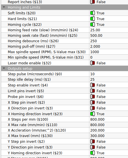
Homing fail. Could not find limit switch within search distance. Defined as 1.5 * max_travel on search and 5 * pulloff on locate phases.
ok
Grbl 1.1f [‘$’ for help]
[MSG:‘$H’|‘$X’ to unlock]
[MSG:Caution: Unlocked]
ok
It refuses to move when homing, If you type $H it enables the steppers (so you can’t move them by hand) But it refuses to move by itself.
The S or Common is used an output from the switch to the controller. On the right for NC is the V and NO is G. My guess, is G is ground and V is supply voltage.
The C/NO/NC are written on the limit switch.
S is the C(ommon) and continuity should be present between it and G or V when:
Not pressed should show continuity to V
Pressed should show continuity to G
G & V should never have continuity.
Something is amiss with the measurements or?
It doesn’t look like you have much choice on how it’s wired, everything seems to match up.
What is being displayed in the console in Lightburn. Can you cut and paste from boot through the attempt to home.?
In the post above here i made the menu which you can open to see what it does at startup. Homing is enabled as you can see in my first post.
I think the V is just to light up the LED if it’s pressed.
But to me it seems that both give a S signal to the motherboard when it is pressed, which is what it should do.