I have recently replaced my Comgrow Z1 because I reflashed it following guidance from the manufacturer and it was bricked. The new one works the same, but the Y-axis seems to have issues with movement. It stutters and jams sometimes when homing it. To fix the homing problem, I manually force the right side of the Y-axis away from the switch, and homing completes.
When I do this I notice that the switch is depressed, so by forcing it away I’m opening the switch. This tells me that once it has hit the switch, it’s not backing away enough for the second Y-axis homing (The machine homes both switches twice). Because of this, I suspect that the issue is likely with the right-side motor, either with the connection, the motor itself, or the belt.
Any suggestions where to start are welcome. If it helps, here is the test pattern I was running while experiencing this issue. Test.lbrn (467.4 KB)
Can you physically locate the switch slightly farther away so that this doesn’t occur?
Make sure the gantry is square to the Y-axis. It’s possible that one side of the Y is reaching “home” earlier than the other which is causing it not be making proper switch contact
There’s a GRBL setting for Homing pull-off that determines in mm ($27) how far away the contacting surface should pull away after a homing cycle. You could increase this to pull away just a little farther.
“Make sure the gantry is square to the Y-axis. It’s possible that one side of the Y is reaching “home” earlier than the other which is causing it not be making proper switch contact” - berainlb
Thank you for your suggestions. I couldn’t sleep so I brought it into the house to tinker with it. It turned out that #2 was my likely culprit.
I loosened the four screws on the end of the upper gantry, pushed it as far back as it would go on the y-axis to level it out, held it in place, and retightened the screws. I also unplugged and replugged the stepper cables for good measure.
It seems to have solved my problem. I’ve tested the most noticeable problem cuts and I didn’t see or hear any issues. Homing so far is working perfectly.
I will rerun my test today to verify at full power to ensure that it wasn’t lacking power due to the draw on the laser (because it was most noticeable @ 250mm/m near 100%). If it comes back, I will look more closely at the mainboard. I have a spare to replace it with if it turns out to be the case.
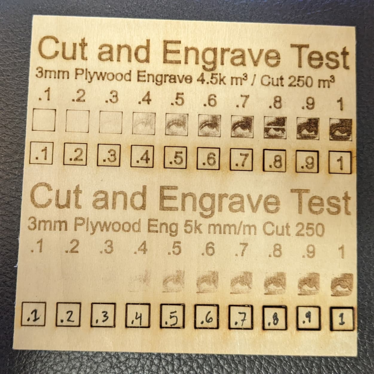
Okay, here is where I am at. I redesigned the test a bit to adjust the engraving darkness, add a border to aid in finding the image borders, and retest the Y-axis portions of the cut. The results are a little different because I more accurately focused the laser beam. Note that I applied tape to the back to keep the cuts in place. But before I continue, here is the test file: Plywood Test 2.lbrn (483.4 KB)
On the cut, .8, .9, and 1 (decimal form to shorten) cut out completely. .7 would come out with light pressure. I think that on this test, 80% gave me the best and cleanest cut.
On the engraving, I think that .7 or .8 were the best. Note that the device disconnected inexplicably twice and needed to be restarted from its last position. it occurred at 80% and 60%.
NOTE: The bottom half is an old test!
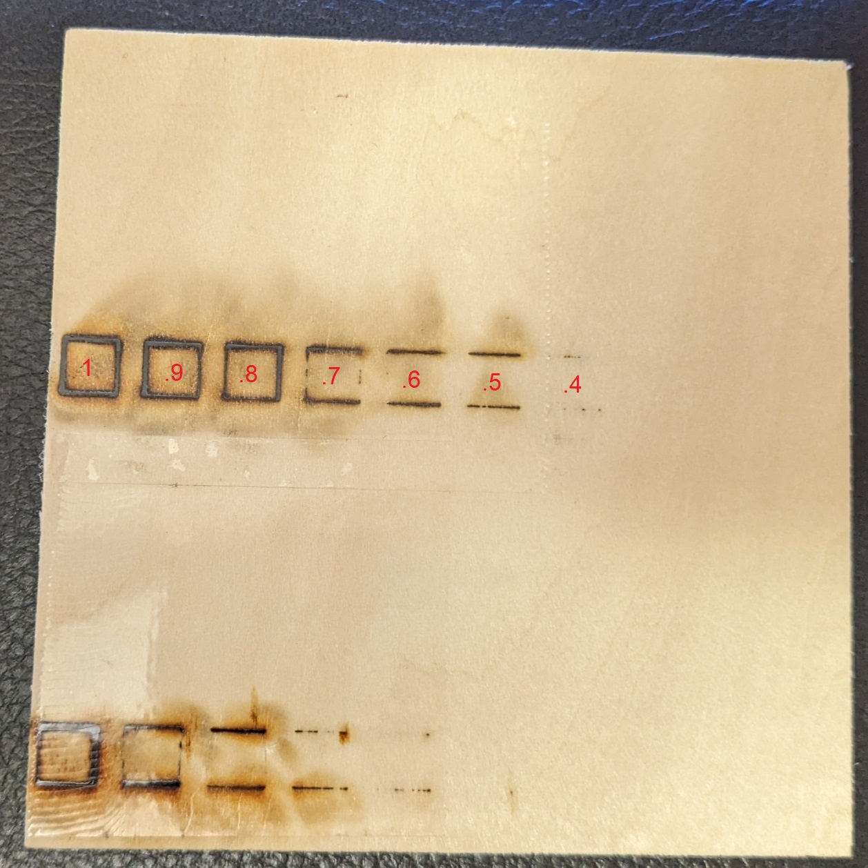
As can be seen from the back, I am still experiencing a stutter on the vertical Y-axis on the cuts. .5 (or 50%) was the last nearly perfect horizontal cut, but the stutter is preventing it from cutting through vertically. If I could find the cause and solution for this, 50% might have been the perfect and cleanest cut.
Again ignore the bottom!
I have not experienced the homing issue again after aligning the upper gantry. At this point, I can only assume that the stuttering is occurring due to a lack of power while powering the laser for the cut and driving both Y-axis motors. I’m hoping that it is a problem with this specific board and I intend to swap it out with my spare. I will post my results.
#Comgrow_Z1
P.S. LightBurn staff, I would love the option to continue a job from the laser’s last known point. I was able to get it from the Move panel’s “Get position” button, but it is difficult to jog to this precise position in the preview panel.
After replacing the mainboard, and adjusting the gantry a bit, I have solved the Y-axis power issue. I am still having an issue with homing which leads me to believe that the $27=1.120 value may be incorrectly set. I am considering setting this to 2. In theory, the gantry will travel further to release pressure on the Y-axis, for the second slower home. If this is incorrect, someone please let me know.
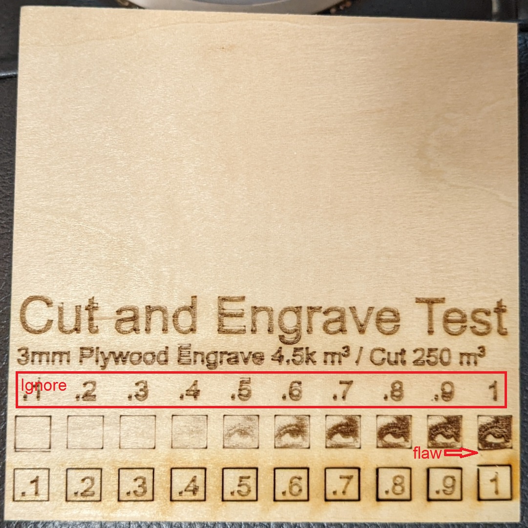
I didn’t change the test pattern at all. Ignore the indicated area, I began the wrong test here and restarted with the correct one. As a result, there was an offset here. Here is the Front of the burn:
For some reason, both ends of the engraving near the bottom had an issue. The area marked “flaw” shows that the burn shifted on Y. I have no clue why this happened. The left side seems to have an extra, misaligned line burned, which could have been caused by me having to restart my job in this area twice.
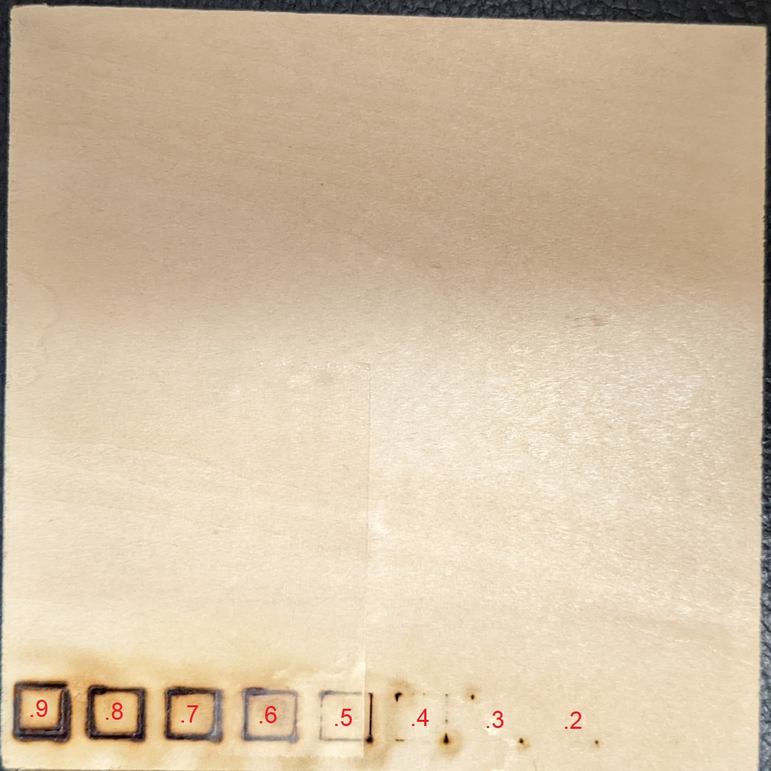
On the back, the cuts were far more even in terms of power in relation to the axis. 70%, 80%, and 90% fell out cleanly. I’m not sure why, but at 100% there was a misalignment in the top left corner that prevented the piece from falling out on its own. Here is the Back:
Note the Typo on the image. I accidentally shifted the values and the area marked “.5” is actually “.6”, “.6” is “.7”, and so on.
The pull-off literally just means how much away from the switch should the head come to rest. The intention is to increase the clearance distance so that there’s less of a chance of triggering the limit switch. Certain designs of switches are more prone to accidental triggers than others.
I think you have a general problem with the Y-axis. It’s not limited to the extreme ends of the X. If you look at the engraved text, you can see that there’s almost a double engraved look or a shadow effect. At some point the Y shifted.
Review the usual suspects:
belt tension, especially on Y. There should be no slack and taught but not stretched.
make sure pulley is not loose on the stepper shaft. Make sure grub screw is tight against the flat portion of the shaft.
make sure you have proper wheel gap between wheels and rails. Hard to tell from these pictures but it’s also possible these are overtensioned.
Make sure you have free and easy movement all over the entire engraving area of the laser. Check for excessive backlash.
I’ll look back over it tomorrow. I agree that there seems to be some travel on the Y. I adjusted the tension on the belts and did the same for the wheels so that they don’t freely rotate unless the gantry is moving. Should I adjust them until they are just tight enough to not rotate, or should they be looser than that?
I never looked at the pulleys since it had arrived, so this could quite possibly be the culprit.
Check for excessive backlash.
Could you please elaborate more on this, I don’t get what you mean?
Again, thank you for your help.
I made a logo coaster before posting this and the travel can be seen between the engraving and the cut. However I had to use Print and Cut because my first at 60% did not cut through, so I set it to 70% and still had to break off some wood. I used fill on the engraving rather than fill and line.
Depends how forceful you’re being and the geometry of the wheel vs the channel it rides in. But assuming minimal force, just tight enough should be fine. You’re really looking to remove the distance between wheel and channel as to reduce mechanical wobble. As long as you’ve done that you’re good to go. Anything more and you’re potentially going to cause a binding scenario.
Imagine an exaggerated case where there are two gears that are interconnected and you’re turning one by hand in order to turn the other. Now imagine that the teeth of the gears instead of being tight and in perfect mesh they are undersized in a way that if you turn the control gear back and forth that there’s a gap between teeth where there is no engagement between the two gears. So effectively if you needed to turn directions it wouldn’t happen immediately but only after you’ve closed the distance in the other direction. That gap distance is effective backlash.
You want to eliminate backlash as much as possible as it makes for distortions whenever you change direction. In systems with excessive backlash you’ll see circles where the start end ends don’t meet.
For burn quality you generally want to avoid this. Better to get right the first time. You’ll need to experiment with this for various materials.
I’d say print and cut works well in scenarios where required tolerance is within about .5 mm. It would be hard to rely on this for something requiring even tighter tolerances. For example, this wouldn’t be a problem if you were trying to line up the X and Os in a tic-tac-toe board. However, it would basically impossible to rely on this to simulate a 2-pass engraving cycle where you ran the job once, moved the sample and aligned with print and cut, and ran again. It would almost certainly give you a ghosted engraving. This might be fine for something to be viewed a great distance but not otherwise.
Higher isn’t necessarily better. This isn’t a situation where you can simply brute force it and get the same quality of result. In this case, you could end up with excess scorching if using a higher power than necessary.
Also, keep in mind that using diode lasers at higher power degrades the life of the laser. Essentially all diodes will degrade with usage, but degradation increases rapidly as power level rises. There’s a general rule-of-thumb not to exceed 85%. The reality is that there many that go over that regularly with good results and staying under that doesn’t guarantee anything. But in terms of averages it likely does help extend the useful life of the diode.
Thank you for all of your help, I’m going to go back over it today to adjust everything as you suggested, especially checking the grub screws on the pulleys. I suspect that the left side of the Y has excessive play or backlash.
On the laser power, I started my cuts and 60% power which were fine for my test, but didn’t cut through it all on the coaster. So when I used print and cut, I got it very close. I ran it again at 70% and it still didn’t go completely through. I ended up just snapping off it was left in sanding it down a bit.
Another thing that I noticed on the coaster was that the engraving was perfect where it started, but it appeared to have decreased in power a bit by the time it reached the top of the project. Maybe by 10%. Not sure how I would deal with this. However on this project the laser didn’t disconnect on me like it did on the tests.
Again I’ll post my results to help anybody else with the same type of laser engraver. You’ve been extremely helpful thank you.
This will depend on the actual cause of the issue. Some things to check for:
material flatness - is the material consistently flat? Is the entire engraving area in focus throughout?
material consistency - you’d be surprised how much variation there can be both between pieces of material and within a single piece of material. This is especially true for natural materials like wood. This is even more true where the wood itself has been processed in some way. Residual manufacturing materials can cause all sorts of issues. Surface prep can help reduce some of this variation. Sanding can help. Some people use baking soda or borax to increase burn constrast.
diode or control issues - it’s possible that diodes go bad. Or power supplies. Or anything in between. This isn’t as likely in your case since you’re working with a new unit but diodes that don’t last initial burn-in are common.
For the cutting issue you had earlier… consider multiple passes at lower power if 1 single pass at higher power doesn’t get you a clean cut.
I’m certain that this was the problem, as my workpiece was set on top of an empty K-cup box turned on its side and a piece of aluminum foil inside to prevent burn through. The top of the board was just slightly further away from the laser than the bottom, which would be consistent with the results that I had.
I am upgrading my workspace as I go, but I have a restrictive budget. I am expecting these 6x12 mm Metal Cone Spikes to arrive today and I will be looking for a perforated sheet of metal to mount them to.
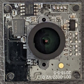
I’ve also ordered a 5MP USB Camera To aid in positioning my work within the workspace. It should arrive within a day or two. It claims to be capable of “MJPG 15fps@2592 x 1944” which is a decent resolution and frame rate is not a concern. It also claims to have a 90-degree lens which should be able to get good coverage, it will just take a lot of adjustment, especially since I don’t yet have a way to mount it to the device.
I also have a plan to design and build an offline controller using an Arduino and some buttons, so that I can control the laser head without having to use the computer mouse to press the software arrows in LB. I might even just use an old game controller or something.
I ran a test on computer paper today after adjusting the gantry again. I made 10mm squares and 150mm squares and they both came out accurately based on my caliper readings. So things are looking good. The eccentric nut on one side of the gantry was too tight. After adjusting it, it seemed to home just fine.
Thanks again for your help! There will be more to come…
Without a mount the camera will be of limited valued. Maybe good enough for rough placement but certainly not good enough for sub millimeter alignment.
This sounds like a cool project. Does the Z1 have a control port you can tap into to do this? Or were you thinking of inserting into the serial connection on the software side?
Sounds like things are chugging along. Keep us posted.
I completely agree, however, while it’s in the garage (and not on the dining room table being calibrated), I have a long solid wood board that is being stored just above it that can provide just enough distance without being tied to the vibrating engraver. The only caveat is if the engraver is moved or bumped, I will need to recalibrate. So I will likely clamp it to my table to prevent this. I also plan to build an enclosure for the laser so the camera will eventually have a good home.
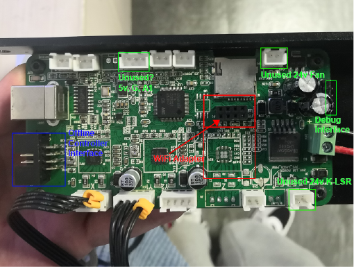
It does, there is an 8 pin connector next to the USB port commonly found on these Chinese controllers Indicated in blue. Along with a 24v Fan connector that I may use for fume extraction in the future. There are also a few other interfaces on it that are unused but have pins soldered on.
There are offline controllers that are likely compatible with it like this, but they are not very intuitive. However, there are a few projects on GitHub that are interesting and could prove helpful.
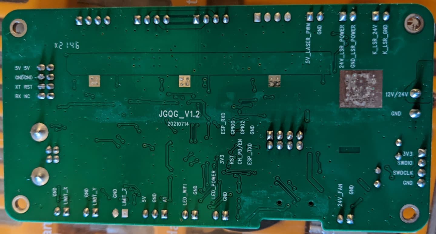
I’ve also considered adding a Z-axis driver using the components from the mainboard that I replaced, but that would be very risky, so I’m not sure yet. I would need to use SMT removal tools to accomplish that. But if I did, I would have another axis to make laser life more convenient.
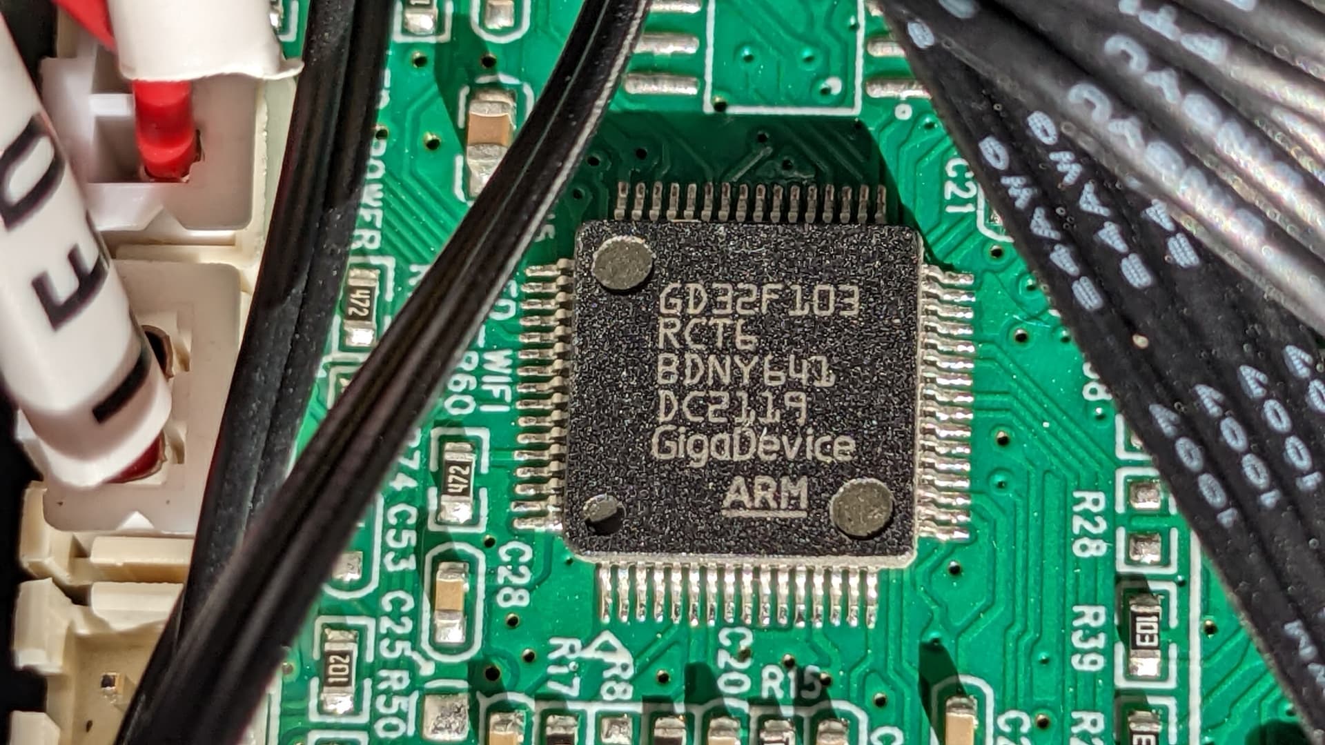
For anyone that may be interested, here is the processor.
It’s a 32bit ARM Chinese-made processor and connects via USB at 115,200 baud. Model GD32F103RCT6
USB is connected to the ARM processor via a CH340G chip to one of the USART lanes.
So my camera came today and the image is great. I think that it will work.
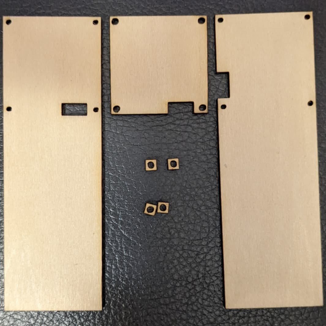
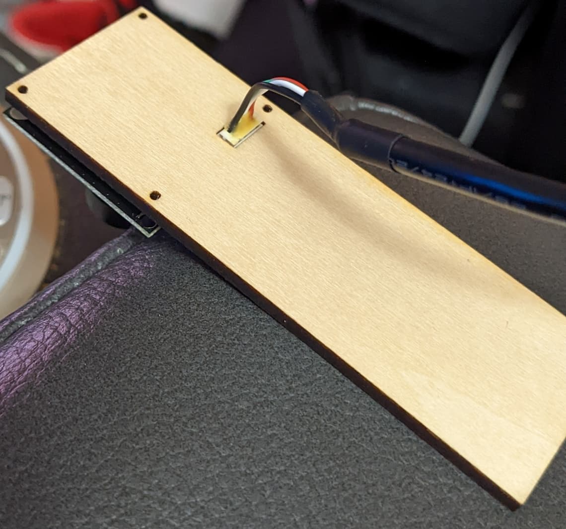
After taking some measurements and creating a bracket that I can use to clamp it to some boards above my workspace, I cut it out. cam mount.lbrn (20.1 KB)
Unfortunately, now I have to wait two days for some M2 screws to arrive to test it all out. But they fit perfectly. I made 3, the square piece is a spacer, with four little ones in case it won’t lay flat, the other two are the top piece for mounting with the clamp, with one positioned 90 degrees in the event that the workspace fits better in that orientation.
Nice. You could get a jump on the camera setup by doing the calibration before actually mounting it. It’s actually probably easier to do the calibration away from the laser since you can control lighting or whatnot.
You will need to have the camera mounted to do the alignment, however. But calibration is usually where people get stuck.
I probably will mess around with it some tomorrow, I’m sure I have hundred mile an hour tape somewhere around here.
I’m really getting into this laser engraver and the LightBurn software. There are so many cool features in it.
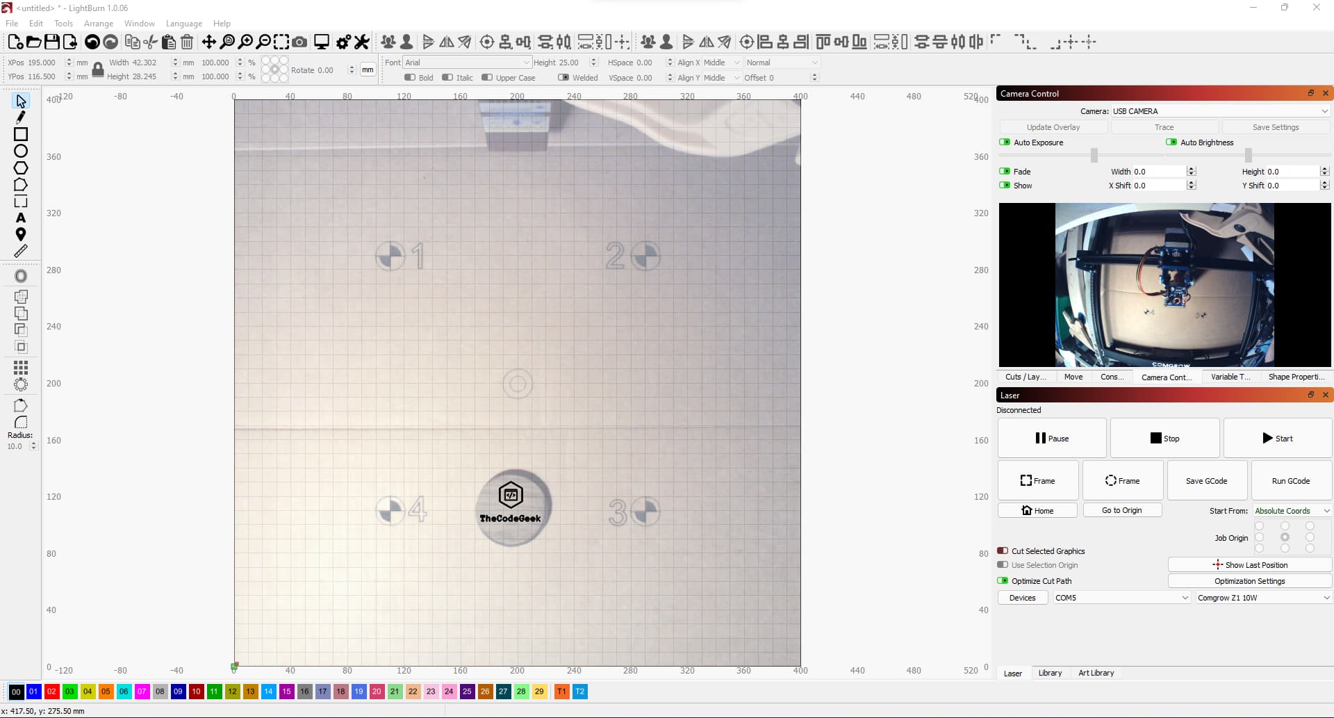
Okay, I’m falling in love with this software. I took your advice and played around with the camera today. I got it calibrated and (mostly) aligned. I threw a scrap piece of walnut up on the bed and grabbed a quick graphic from my library.
I wanted to share something that I found on this forum that I found to be very helpful. I found a post referring to some software called VirtualHere that allows you to connect to your devices over the network as if they were physically connected to your computer.
I pulled out my old Raspberry Pi 3B and using Raspberry Pi Imager, I imaged the Lite version of the default OS. I ran the script as suggested, connected my camera via a powered USB hub, and was successful in getting it to connect to my computer. But note, that The RPi could not be connected wirelessly, I had to connect the Pi using an ethernet cable, but my computer can connect wirelessly.
Now that the original problem has been solved, I will be starting a new post to log what I’m working on to share with others. I will include this topic for reference. Thanks for your help!