@StevenM @Colin
Well, I had my doubts about the taper warp. Seems I was used to warping the other way for sandblast masking for tapered things.
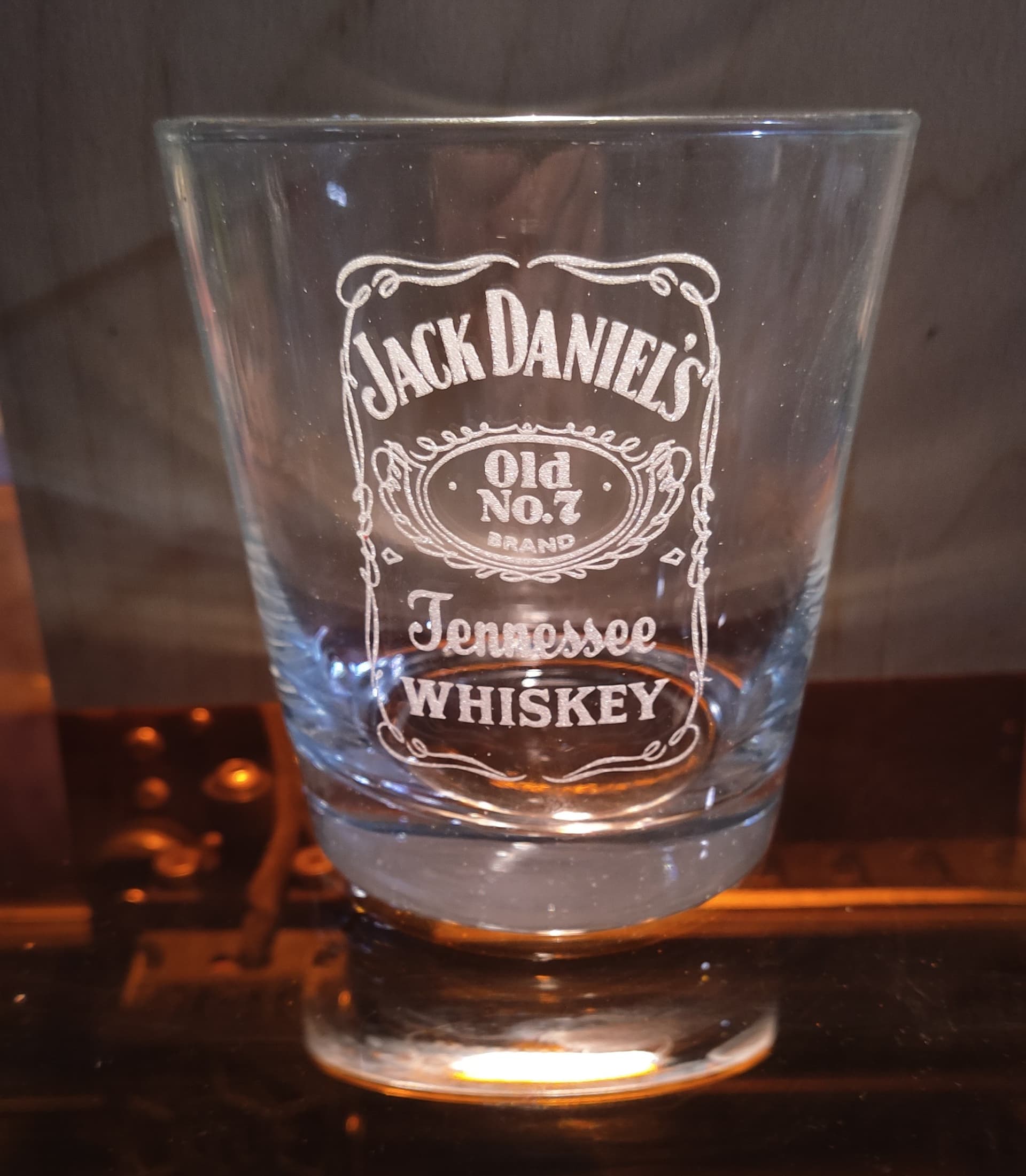
It looks like it does just fine. (just had to prove it to myself)
You be the judge.
@StevenM @Colin
Well, I had my doubts about the taper warp. Seems I was used to warping the other way for sandblast masking for tapered things.
It looks like it does just fine. (just had to prove it to myself)
You be the judge.
I was under the same notion. It honestly did appear to me to be backwards in its result. Otherwise, wouldn’t have challenged it.
Excellent news then!
Thanks for verifying.
I did a bunch of Glass pints for an organization here recently using taper warp, and as you found, they turned out beautifully. Image looks perfectly straight and the customer was very pleased with the outcome.
@sutick Congrats on your success!
Curious if you had to do any stretching/resizing the graphic before you pressed the Start button.
There’s a reason Silhouette’s Taper module has additional parameters (and others for %wrap coverage) which I’ve used with success as well, before LightBurn’s release of its Tapering Module. I’m not interested in creating a template but it seems to me, in my finite mind at least, that where you place it and how wide you intend to apply to the substrate comes into play. A short heighted object may not reveal itself to anomalies.
I soooo…wish my chuck rotary was working so I could test my theory. Maybe it’ll be back up an running by the next weekend. I’ve let it lay due waiting on this release. Too many other customers wanting things and I’ve been holding them off on rotary items.
Would you mind looking at what I’ve played with today to show what I’m seeing?
If I bound the graphic within the same shape as the taper, I’m getting differing results. Again, other’s are incorporating them for a reason.
TIA,
Steven
Taper Comparison V2.lbrn2 (1.3 MB)
The design in question here was a company logo with text above and below the logo, making it basically a rectangle shape that covered a lot of the surface of the pint glass from top to bottom. I did have to widen the whole graphic out a little bit, as there was a circle in the middle of the glass. In reality, the circle comes out being wider than it’s height, but need to do that to correct for the optical illusion you get from the circle on the rounded object. I didn’t have to worry much about vertical placement on the glass in this case, as stated, it filled most of the glass. Can’t share pics at this time unfortunately, as these are for a charity event that hasn’t happened yet.
Appreciate the feedback!
Apologies in advance as I’m sure this is getting old for you all but this is important to me.
Some time ago I started using a taper warp method that I found posted on the instructables website. I utilized the equations to create a spreadsheet that would calculate the points/locations of the warp needed while including additional information. Feel free to play and extract the formulas as desired. My chuck is 80mm and that’s what I’d be using instead of the 100mm found in the spreadsheet. I only used the 100 to match and verify that the calculations matched what’s in the original pdf.
I also mettled a little with the new LighBurn taper feature and got to thinking more about what/where exactly is the output was in relation to the object being engraved. What I’ve discovered it that it “appears” that the output’s bottom is resting on the top of the taper. Please look at the information contained in the LightBurn file, particularly within the purple outlined rectangle.
In my minnd, proper placement seems to be important.
Rotary Taper Image Adjustment.ods.txt (136.4 KB)
Tapered Mugs Image Adjustments for Rotary with Drinkware Adapter.pdf.txt (17.1 KB)
Just call me cray-cray. I’m okay with that. Ha!
The taper tool is set up for a constant taper.
If you measure how wide you want your image to be, it will be fine if you put it at the top, middle or bottom. Try it on cheap dollar store rocks glasses (as in the pic I showed in the first post.)
If you are trying to do a full wrap, it may not work for you.
I do not understand why you are putting a border (outlined rectangle) around the image.
Now, if you are trying to cut vinyl to put on the glass or use as a sandblast mask, it will not work. That is a different thing completely.
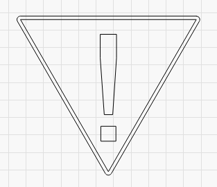
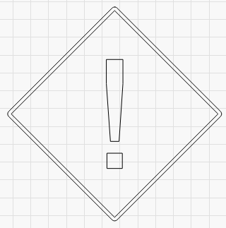
I’m considering the border as part of the object to be engraved. Moving the internal diamond/circle/square (dcs) within the confines show how it alone is impacted by placement location. Yes, as you’ve noted, it (the bounding blue border) has the same taper regardless of where the internal is placed.
But… the dcs is definitely affected at varying locations.
Maybe I shouldn’t be marrying the two together but even if it’s the same taper, moving it downwards surely affects the width.
Yes, the internal image will change with position inside the rectangle. It sounds like you are thinking you have a strait sided glass and want to taper the glass, not the image.
BUT, if you feel the need for a rectangle around the image, then you already know where the image will be placed.
If you are only putting a rectangle around the image to try to prove it will not work is useless.
Etch some glasses and try it.
Valid point.
And if there’s no rectangle, then I simply move the object vertically and then scale it accordingly. That part I already understand.
Thanks
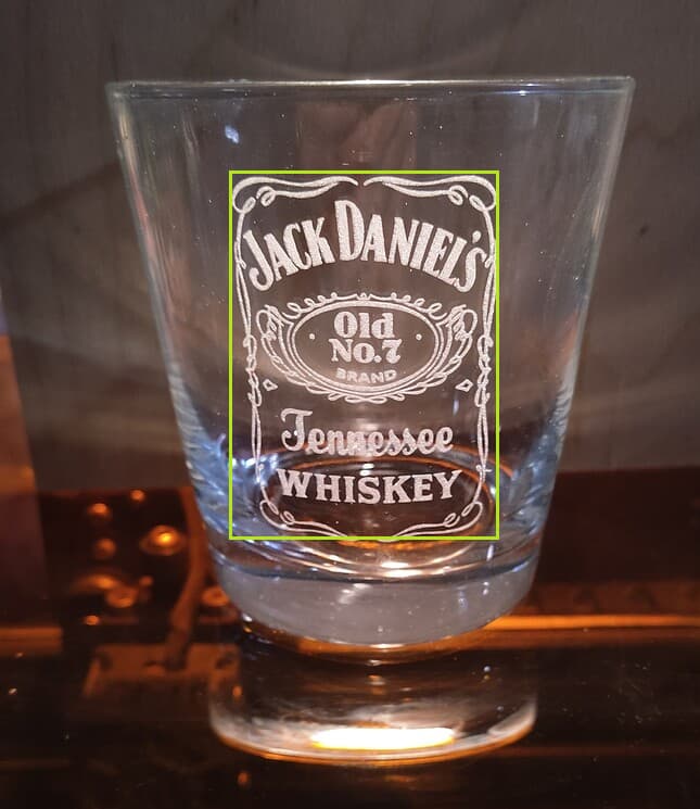
Are my eyes deceiving me?
Because after drawing vertical lines down the side of your engraving in a simple paint program, it looks like it should’ve been a little wider at the bottom.
When I get some glasses engraved, I’ll set a 1-2-3 block or a square on the table and eyeball down its side. For now, all I can do is this.
@adammhaile (since you’re not accepting private messages at this time)
I need your help!
Could you please look at this thread and the one below where I’m imploring the addition of the location and width to the upcoming release of the Taper Wizard?
External Sites that point to the necessity of identifying proper location of the image during taper generation:
This one specifies a needed vertical location
https://support.thunderlaserusa.com/portal/en/kb/articles/rotary-roller-diameter-calculation
This one specifies a needed vertical location in its calculation pdf. The spreadsheet that I’ve created was extracted from that pdf and uses placement and is found in one of the links above. Name: Rotary Taper Image Adjustment.ods.txt
Placing the object that’s been run through the current tape wizard creates a modified, to be engraved object. Place it on something short and it’s hardly noticeable that the taper is still not correct. But, suppose the object being engraved is a rather long item. Whole different outcome of the engraving as it’s moved downward. Let’s say the long object is 8" at the top and maybe 2" at the bottom… an oil filler funnel with a full length is 12". Now take that image placed at the larger end and move it towards the smaller end of the taper and it will wrap around upon itself if it’s a large image.
Yes you can shrink, spread, massage… whatever you need to do to get it to fit. But why? There’s formulae and calculations already established that take these parameters into account on the front end of their wizards. Others have incorporated them for a reason.
This new Taper Wizard in LightBurn is soooo close to being what’s been waited for, I’d hate to see it released “half-baked”.
I’m aware that this message will certainly tick folks off, but I’m one of those persons who had to go purchase external software (Silhouette Business Edition) just to get their functionality for their Taper Wizard. I’m suspecting others have as well. I don’t like purchasing things that I don’t need, but I did because of the above.
I could just keep on using SBE but I’m thinking about other following after us.
Warm Regards,
Steven
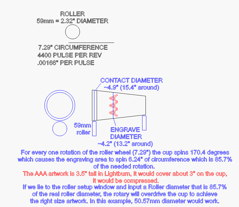
Also, see notes at bottom of this image
Taper Wizard is an entirely different tool that Cylinder Correction - it’s not the “for gantry machines” version. Completely different intent (cylinder correction doesn’t correct for a taper at all) and completely different code.
I will however, pass this along to @LightBurn who actually did write Taper Warp. I honestly don’t know how it works ![]()
BTW, I understand the desire for a private message, however we have good reason for never accepting them. Mainly that if we fix your issue privately no one else gets to benefit from that information being public. Tagging in the forum is totally fine though ![]()
I’m curious - What prevents you from simply drawing a rectangle using a tool layer that is the height of your cup, and placing the logo along that rectangle?
The problem you’re describing here in your post is specific to roller rotaries using the wrong diameter to drive the object, but easily addressed by making your design match the height of the object you’re engraving on by adding an outline (that doesn’t have to actually be engraved).
You are correct that I can add an “offset from top” value to make the taper warp tool do this for you, but you make it sound as though it’s completely unusable in its current form when drawing a rectangle would fix it.
I read the original post you linked and it’s not clear from that what you’re asking for in the “amount of wrap around” bit. Are you suggesting the user needs to supply this value, or I need to output it? I could calculate it from the bounding box around the design, but what do I do for these shapes?
I could potentially draw an “opposing” rectangle over your design to show where the wrap would occur, similar to the “show boundary” feature in Cylinder Warp.
That’s essentially what I did in the taper test lbrn files to show how that outer perimeter affects the outcome of the internal object being engraved. However, I don’t think I would need to if the wizard utilized that height internally to do those calculations in the background beforehand along with distance placement from the top (which you agree affects the outcome).
The post was just to use as an example of where others have acknowledged the placement along the vertical gives a differing effect. Nothing more than that. Sorry if that wasn’t clear as to my usage of the example.
If I have a cylinder/taper that I want to see all of the object being engraved while looking straight on, then I wouldn’t want a full wrap (100%). I wouldn’t even want a half wrap, again looking straight on. I’d suggest something more like a 40% wrap to give some sense of border at the edges of the object. However, if I were doing a full wrap, then I know the image/object would meet/join on the opposite side. Wouldn’t be usable in all cases but some repeating tessellations would be if they were drawn properly to start with. Or maybe the end user is okay with doing a 80% or 90% wrap in order to get the whole object on the item and in a size that’s readable or recognizable.
If there’s a bounding box internally based on the object’s size, then that would work. I’ll point you back to the taper test files in uploaded with the diamond/circle/square.
So there you have it. An internal bounding box located a specified distance from the top (new input field) with a reference in percentage (new input field) of just how wide you want it to be rendered. Of course changing the width also would change the height since you would most likely want to maintain aspect ratio. Also having the numbers that are in the field remain for tweaking before applying would be beneficial as well as being able to save the parameters for future use, i.e., once you “built” a file for a 20oz tumbler, you could open it at a later time for another design with most of the parameters already there. Then it’s just a matter of tweaking width and height.
Place the item to be engraved in the rotary and align/frame the engraving to match where you intended it to be engraved on the item.
But this is only true when using a roller rotary, or “driving” the cup with the wrong diameter when using a chuck, and both problems are solved with the addition of a simple rectangle, while you suggested it was so broken you needed to go to entirely different software, hence my confusion.
I think what you’re suggesting here is that we allow the user to edit the various fields of this tool after the fact, but like the Warp and Deform tools, the Taper Warp tool applies the change to your shapes and is permanent. You can undo it, but you can’t go back and edit it, in much the same way you can’t go back and alter the distance of an offset.
Looking at the file you’ve provided as your reasoning for needing additional fields, I’m honestly more convinced that you just need to add a tool layer around your design, as otherwise you’d have no simple way to verify the placement on the rotary. If you framed the rectangle, it would line up the ends of your cup and would be trivial to align. If you decided you wanted the design placed 35mm below the top of the cup, you’d have to measure that, and frame using some marked reference point on the cup, which seems harder to me.
Am I missing something? This feels like a mountain being made from a mosquito bite.
Have you even tried the taper yet?
You can not guess at % coverage. You have to measure the size of your image and what you are putting it on to get a sense of how much you will actually see. Once you have that size, not a %, then size the image and you are done. Punch in the numbers and run it.
I have to agree with Oz here that it is being overblown. Especially if you have not even tried it yet.
I needed to go to other software because this new wizard was several years in getting enough attention before becoming available. And FWIW, I didn’t say it was “so broken”, only that it was half-baked.
There’s a plethora of comments over the years asking for a taper wizard in all forms of Feature Requests, forum how-do-I’s, etc.
I knew there would be fur raised by pressing someone’s proverbial button on this matter. I make no apologies for that on behalf of multitudes of folks saying they needed this.
If I have to use it with a push-pull-tug-tow mindset, then so be it.
Honestly, I have my 89 year old mother-in-law with me who’s in her final stages of dementia. I’m surprised I even found a moment to gather my thoughts to even write this. She’s currently resting on the living room couch. So, no, I haven’t had an opportunity to do anything since the beta hit the streets.
I’ll shut up now and just see how it goes when I get the chance. All I really wanted was for someone to take a hard look at what was going on based upon my thoughts and previous experience.
Of course, I know I can’t guess at percent coverage. Math is involved like you said. I don’t really care if it’s percentage or an actual width. The adjustment “should” yield the same results however the end user feels best to input it…
I do apologize for that if that was too much to ask.
Have a good day, gentlemen…
I’m not opposed to adding features to the tools we make, and I’m the last person who’ll claim that everything we do is perfect, but when you use insults when trying to plead your case for changes, it doesn’t come across well.
Often when we release a feature that’s been requested a lot, the responses we get are “oh, but it doesn’t do everything I wanted it to” instead of “cool - that gets me 95% of the way there” and that’s disheartening. A better way to phrase your request would have been, “this is great - an idea for a future addition would be…”
We have to find the line between making something that does what most users need with a clear and simple UI, and overcomplicating something so we can handle the last few special cases.
This is an example of that. So far, everyone I’ve sent the new taper warp tool who does lots of cups and rotary work has been really excited about it and found it useful. We have a LOT of users who are new to lasers, and we’re trying to improve the overall usability of the software, and reduce the fear people get when they’re confronted with a wall of options.
Since it’s easy to add a tool rectangle around a design, it felt like you were putting an excess of importance on adding another parameter to the tool for something can be done simply already, and I personally prefer doing it the visual way.