I have looked at all of the other posts with this or similar problems and have gotten no idea of how to adjust this. A project that is supposed to take 4 hours 18 minutes took 8 hours 11 minutes. I had Lightburn read the information from the controller and my new estimated time is 5 hours 27 minutes. A far cry from 8 hours and 11 minutes. One of the posts suggested changing Cut Speed Scale and Global Speed Scale to 200%. I expected a huge jump in time and the time increase was about 20 seconds. Then I set the two scale settings back to the 100% that had been there. I then went into my engrave settings and increased the speed from 26,000mm/min to 36,000mm/min. With that big of a speed increase, I expected a significant jump in speed. The time should have dropped but actually increased by 14 minutes??? Something is wrong with the time estimates. I’m using Lightburn 2.1.04 on a Windows 10 machine. The laser is a Longer B1 40W/48W. Lightburn should not be showing a longer time when I increase the speed significantly. If the job is running significantly faster, it should take less time, not more.
DISCLAIMER: Nothing I write in this specific posting is documented, suggested, hinted at, approved, or authorized by Lightburn Software. It is my own theory, period.
Yes, and no. The time estimate is based on theoretical values. It impossible to know how your specific machine will react with all possible motion commands. My experience with 3 different diode machines has been that a vector (path) engraving is pretty close. Images not so much, with times ranging from 1.5x to 2.0x more than the Preview window estimates.
Now my Preview is within 5% to 10% for all work. How did I do that you say?
- Initialize values with the Read From Controller, which you did.
- Run a project that is vector-only that lasts maybe 30 minutes (record the time from the Preview window). No need to actually burn anything, just set the power to 0.1% (unlikely to light up the diode). When it finishes, touch nothing. Look at the bottom and you will see the actual run time. Write that next to your Vector Preview time.
- Next run a 1 hour project that is image-only (record Preview time on another line). No need to actually burn anything, just set the power to 0.1% (unlikely to light up the diode). When it finishes, touch nothing. Look at the bottom and you will see the actual run time. Write that next to your Image Preview time.
You now have two sets of numbers.
- Divide the Preview by the Actual for the Vector test. That is likely close to .98 or better.
- Divide the Image by the Actual for the Image test. You will see .6 to .7, but can be anything for your machine.
Now here is where the magic comes in. At least for mine, if you average those two answers, you will get close to the correction we are looking for. I did not know this last part until I had done a lot of trial and error with my settings. I had those image time errors mentioned above, yet look at the actual entries that got me real close.
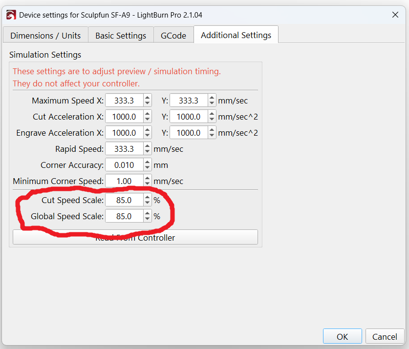
What I write may work for you, or not. Feel free to try different from eachother percentages in the circled boxes below. You may have to experiment on your own.
Often, overscans (acceleration and deceleration) from a certain speed become disproportionately long and make the overall processing time longer. But this should be easily visible in a preview.
Assuming it’s that machine, then the rated top speed is 20000 mm/min = 333 mm/s. Compare that with the controller’s actual maximum speeds in GRBL’s $110 and $111 parameters to see how the claim matches reality.
Although you can set the LightBurn layer speed to any value you want, the controller limits the machine’s actual speed to prevent any axis from exceeding its limit. That comes into play when the layer’s Scan Angle is anything other than 0°, but for ordinary left-to-right scans the X axis limit is as fast as it’ll go.
If the engraving isn’t one large block spanning most of the platform, then the time spent in the overscan areas while accelerating to the maximum speed and decelerating to a stop will account for most of the job time. Comparing the Rapid Moves time in the Preview window with the Cut Distance time will give you an idea of how the scanning speed affects the job time.
If you’re numerically inclined, you can feed the GRBL $120 acceleration limit into the RepRap speed calculator to determine the distance required to reach any given speed. Note that you must convert the speed from mm/min to mm/s. The result of that calculatIon may suggest using a much higher Overscan distance than the default 2.5%.
There are lots of reasons why actual job time and estimated job time may differ.
Most grbl machines, if I remember my grbl, for vectors you tell it go this way for this amount of distance. For an image, it must send each bit and with grayscale, it has to also change power levels.
If you want a fast, with the same larger work area, you need to get it to accelerate faster. Each axes has an acceleration value. This actually determines how long and how much distance it takes for you can get to a certain speed. X is commonly used as it’s the least amount of mass compared to the Y axes. The Y axes carries the all of the X axes mass, such as it’s motor, drag chain, pointer and whatever else is on the X axes.
This is in @ednisley comment and is acceleration. My machine has a very lightweight head on it and can run at 1650mm/s, however it’s pretty much academic for various reasons. However the axes acceleration applies in any circumstance.
You can use the preview in Lightburn to show you the computed paths and times. Lightburn emulates the machine to build the preview, with show transversal moves is enabled the path of the head is output on the screen as red.
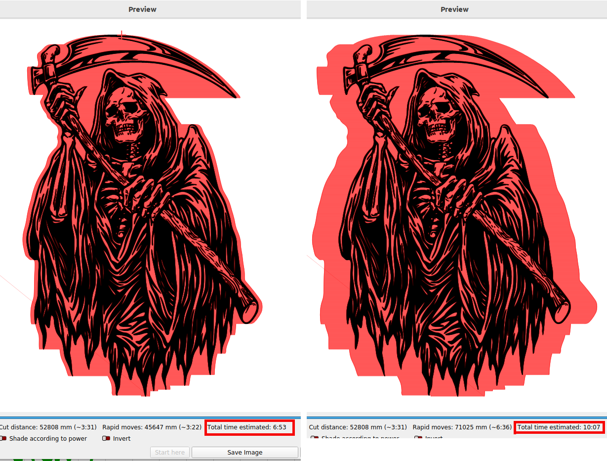
You can see, visually the red outline on the right is a 6,000mm/s^2 value for acceleration and on the left is overscan for 40,000mm/s^2. Note the time difference.
This is pretty obvious when watching it operate. If it’s over-scanning the same size area as it’s work exists, it likely isn’t saving you anything by running faster. Usually you can see it in the preview.
DSP machines, like my Ruida compute this overscan internally, but only if your angle is a multiple of 90 degrees. If you use a different scan angle you have to handle that in the software.
You can get lots of information like this, so we welcome your comments.
Main thing is to have fun.

Thank You everyone for your information. I’m going to change the overscan just see what difference it makes, if any in preview.
I did discover an issue with my laser. As recently as about a month ago (estimated) the max X and Y speed were 600mm/sec (36,000mm/min) and it was now set to 100mm/sec.(6,000mm/min). I contacted the manufacturer and they told me what two values in GRBL needed to be changed and what to change them to. When I read from the controller now the max X, max Y and rapid speed are all coming up as 600mm/sec, as it should be. I still don’t know why changing Cut Speed Scale and Global Speed Scale doesn’t change preview times.
I went into my profile, here on the forum, and could change my profile, but I can’t find where to change the machine I am using. It still shows the old Ortur LM3 instead of the Longer B1 and I haven’t found an option to correct it.
The profile update is cleverly hidden at the bottom of the License Management dropdown, not under your Profile picture. I have no explanation.
Thank You! That was it. Weird place for it.
Thank You Again!
I have nothing more to add to what has already been said.
The only doubt I have, and if I have it, someone else might too, is related to Mike’s comment.
When you say “you will get close to the correction we are looking for,” that means this value is the value to be manually entered in the “Cut Speed Scale” and “Global speed scale” fields?
By the way, I think it’s useful for everyone, what is the meaning of these two fields? What do they specifically refer to?
In my version, yes.
Excellent question. I did not look it up, but I initially guessed Cut Speed was for vectors and Global Speed was for images. Obviously that is not the case with both being equal. I also initially thought 2x too long meant enter 200%, but as you can see, it is below 100% and not even close to any expected ratio. I think I have made enough wrong assumptions that @JohnJohn should jump in and correct me. 
Bottom line is just to play with them until you are happy. Thank you @Kuth for asking. Asking is good 
If you look at the documents, they do not really explain what these two setting functionally change how the machine emulates your machine.
Maybe @Aaron.F can shed some light on it for us. 

I’m still not sure when to use “Cut”, vs “Global” speed scale.
Will ask the team and report back.
That’s one way to say what I am looking for.
Okay, after weeks of inactivity, I’m back to create a headache for the developers.

Just to clarify, it’s more out of curiosity than necessity. 
Thank you all for the clarification. 
A lot of people have complained about the guesstimate error. I think it is more than a curosity.
When someone mentioned the actual run time was at the bottom, at the end of a Run, that really helped a lot. Just don’t touch anything before you write it down.
I have to watch as the process goes and monitor the time near the end of a run, because when the job completes, the run time disappears. It would be nice if it remained on the screen for reference.
I believe the time is in Console window after job ends.
I am pretty sure it stays until you move the mouse.
I hope you are right!
EDIT: It does show in console. It also seems to be “sticky” in v2.2.00-Beta-6 as well. I was able to click around and not lose it at the bottom of the design grid.
“Global scale” basically adjusts everything at the same time. The Cut speeds are for vector cutting and offset fill, the Engrave values are for images and fills. On GCode based machines they’re almost always the same. On DSPs they may differ.
The global speed scales are still subject to acceleration limits though, so if the job is accel limited, boosting those numbers might not change anything.
Another question:
If I set my global to accurate for images, and it is too much correction for vectors, does the Cuts % modify the original total or the 85% in the Global setting?