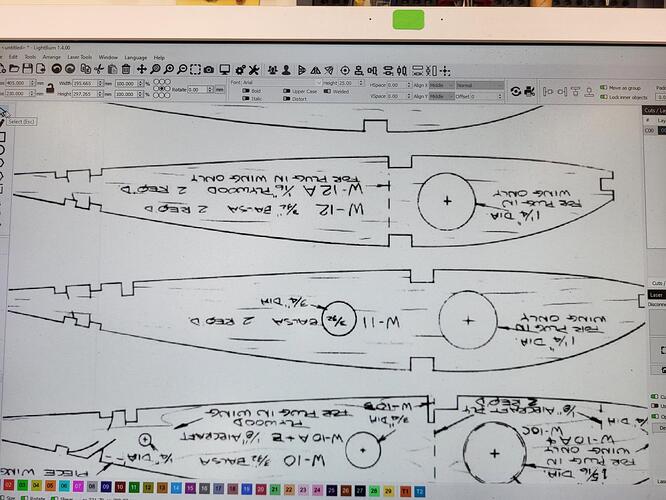
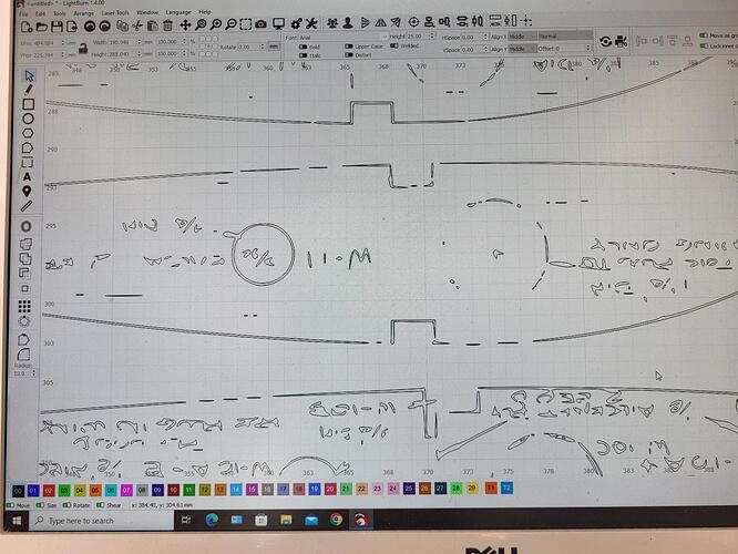
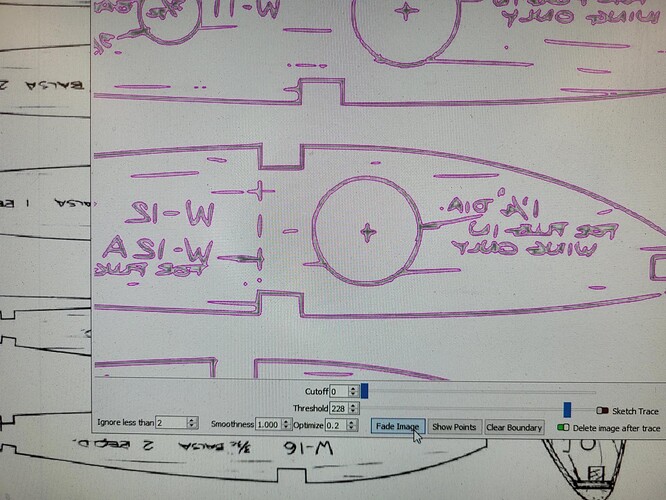
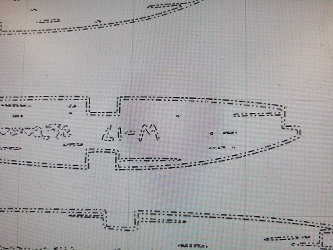
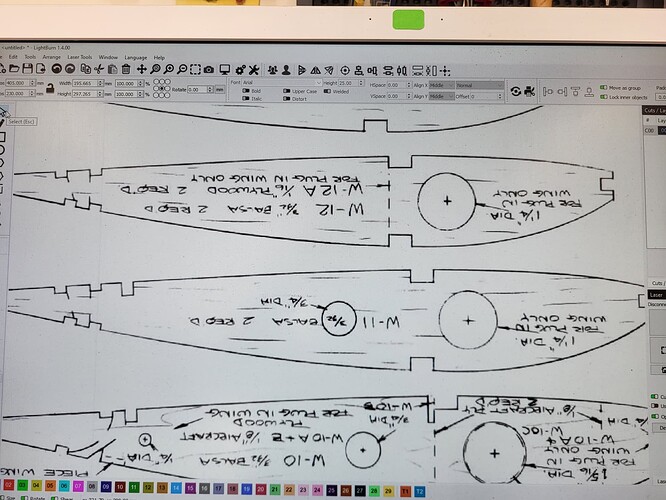
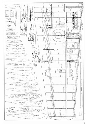
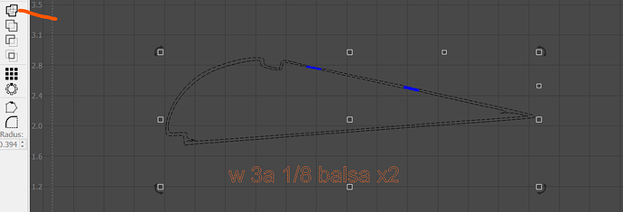
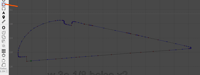
So I have 4 PDFs that I have used the trace function on, 3 no problem but one of them creates a double line from a single solid line, I tried using the sliders at the bottom of the trace screen with no luck.
Any ideas how to correct would be greatly appreciated TIA
If I am understanding correctly, this is expected behavior. If willing, share an image of what you are working with to help us “see” what you are after. The ‘Image Trace’ tool will produce the double line output and does not currently provide a ‘Center-line’ trace function. ![]()
I suggest you check the first 3 again. They should also have a double line. If not, something else is going on.
Try tracing only one portion of the image at a time by creating a bounding box around the shape you want to trace in the Trace window. This will allow you to tweak the sliders more precisely to suit each trace.
I also note there is a lot of “noise” (smudged lines, unwanted artifacts in the image) in this PDF. Would it be possible to find a better rendition to start with?
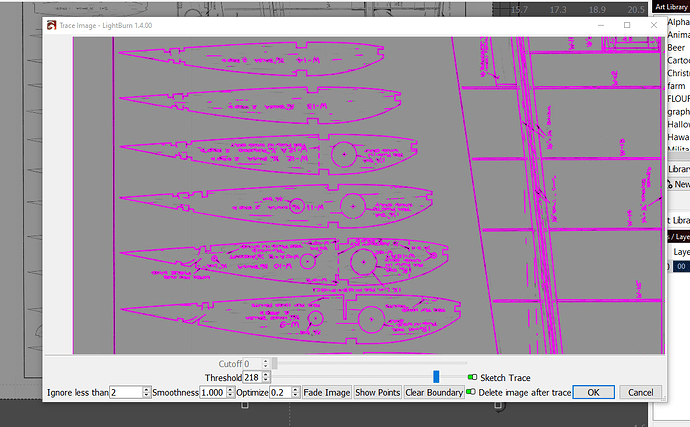
@berainlb is correct. Your “no problem” image traces should also be producing double lines. You may find ‘Sketch Trace’ produces better text results, highlighting small sections of the overall image.
Making wing ribs for RC planes! Wahoo!!! Great use for the laser.
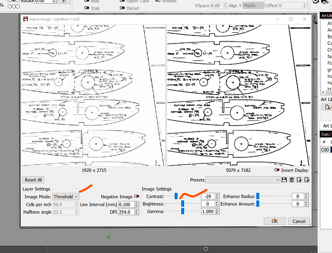
I would try driving brightness and contrast to try to improve the image, also.
Or… print the jpeg on paper and then trace a photo of that under bright and even light. Sunlight is better than shop light, for my photos.
Okay, tried both options suggested, same outcome. Will try to clean up the PDF tomorrow
Thanks to all
Can you post the pdf here, and give us a shot at getting results? I would be happy to poke at the problem a bit. I have done some editing of the nodes to fix minor problems. I assume balsa wood is pretty forgiving to work with - and lite ply is not terrible, either.
Can you upload the pdf file, not just the pdf screen shot? Sorry if it was not clearly requested.
BTW - what is the airframe? Looks like a sporter acro model, although those ribs may not be relieved for sheeting.
10 quick minutes playing around with the screen grab. got one rib out of it.
rib trace edit.lbrn2 (76.7 KB)
Gotta go to work right now, but will work on it while I have time.
You will have to adjust for Kerf - the thickness of the laser spot. My laser is not square, rather it is a rectangular beam. The horizontal cuts will be different from the verticals. That is a topic for another thread.
Jim,
What am I missing, I’ve spent an hour trying to get that with no luck?
I will be happy to share with you what I have learned. It will take me a little while to document the process with screen shots. We have a graduation this weekend, so i may be a little longer than usual.
Generally: - it is easier to do than to explain.
adjust the image
Poke the sliders around to get best contrast possible
trace - play with those sliders
trace and delete all the junk that is not part of the outlines you want to have burn
node edit to smooth out the jaggies
fill in gaps with boolean tools
set object to line - then delete the inside shapes
group the whole image together and scale to correct dimensions.
Thanks I will try it
Rib 7 - the lower leading edge hard ply cuts did not get included. Scaling will be the hardest part for consistency. The 3/4" hole behind the spar would be where I would gauge scale. This file is set to FILL so you can see it. Before you go to production:
change blue layer to black
change black to LINE cut, rather than FILL
Click here to download this cut file …
rib7.lbrn2 (2.8 MB)
Import the PNG. Adjust image by dropping contrast
Make the trace a tool layer and move it away from the work area.
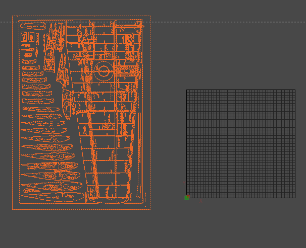
Right click to TRACE - play with the sliders to remove as much noise from the image as possible. In this instance, I used the SKETCH TRACE button
Select ALL - then ungroup. Use the red lasso tool to select all the parts of one rib and move them to the work area. Select and delete the garbage and the parts that you do not want cut (tech info, size etc) REGROUP those parts to keep scale ratio,
The art of the deal comes next. Getting the outer most line isolated and cleaned up. Set the layer to black and to LINE mode. Ungroup and select the inside line. Delete the inside line. On this example I had to separate the inside from the outside. That was a matter of boolean weld outlines to complete the shape and node editing to break the lines where needed. That will be another step by step.
next step by step:
node edits - same process to isolate one part at a time
select and delete unwanted artifacts and notes
patch holes in the outlines with shapes
Select patch and outline - use BOOLEAN tool to WELD outlines togther
Ungroup and delete inside line
Select NODE EDIT to push nodes and handles to change shape as needed. It is better to leave the parts where they need final sanding to fit rather than use filler to fill gaps
Right click and LOCK the shape until you need to move it to the workspace. It is a lot of work to get to this point, don’t waste your efforts.
