Trocen AWC7813 ramp problem

Hello!

I built a CO2 engraving machine with a 640*430 mm work area, with a Trocen AWC7813 controller.

I have been using the machine with great satisfaction for half a year, but I just encountered a problem.
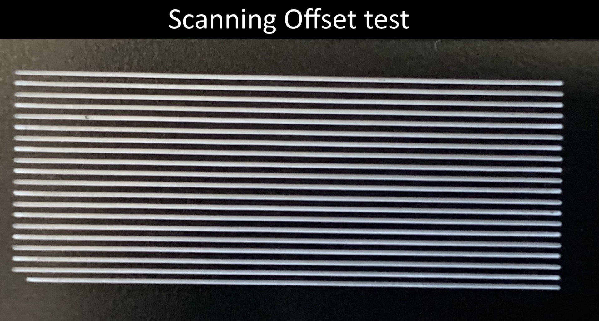
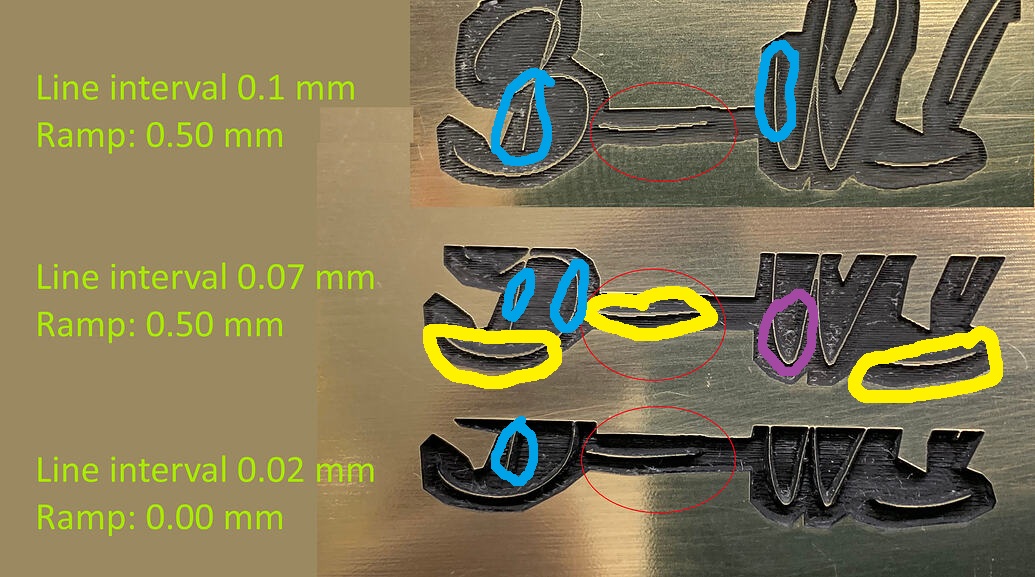
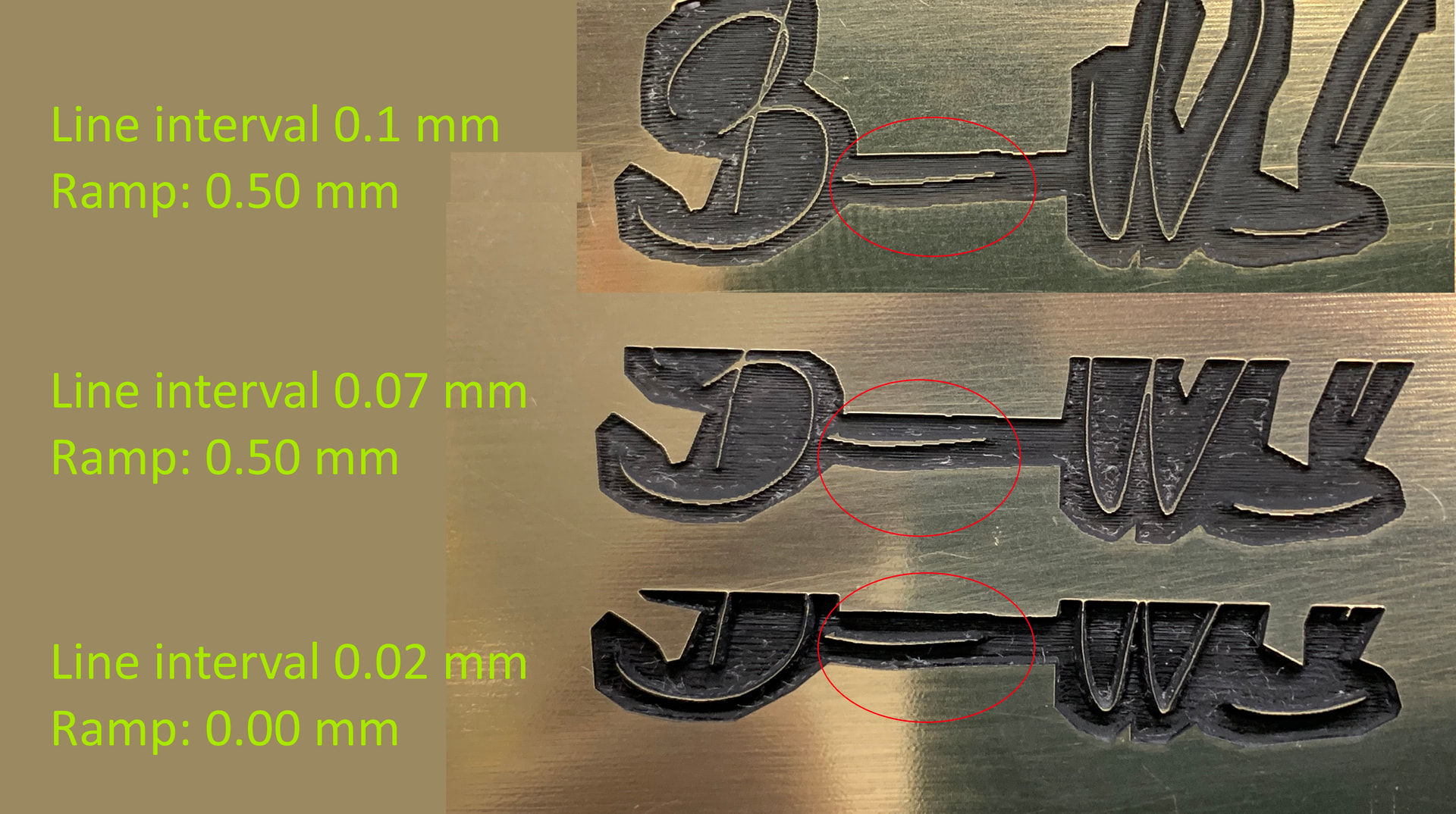
If I set a ramp around the lines when making stamps, say 0.5 mm, then as the machine reaches the edge of the ramp, the X motor starts clicking strongly, and the whole work shifts to the left.

You can hear the phenomenon in this video:

In this video, a line interval of 0.02 mm is set, the best resolution of the stamp is below this.
If I set the line interval to 0.07 mm or higher, there is no clicking sound, the machine works normally, but here the stamp imprint is no longer beautiful, with reduced resolution.

My machine works best at 310 mm/s, so I use it at that speed.

Trocen customer service could not tell me what the problem could be.
Ligthburn customer service had several ideas, with them I figured out that if I set the line spacing higher, the clicking sound would stop.

I tried reducing the speed, reducing the acceleration, but nothing changed.

Has anyone encountered this problem? Does anyone have an idea what the problem could be?
If someone has such an AWC7813 controller, would you try it on their own machine?

havanna alairas.lbrn2 (86,1 kB)

I made a video about the machine:

Thanks for the help!

Kristian

Looking at your artwork, I don’t see anything that would cause an issue with the Z axes.

One of the issues, is that most co2 machines produce a spot size in the 100 - 200 micron (0.10 - 0.20mm). You are going over the same area multiple times. I’d expect a 0.10 or somewhere near there as an interval.

I assume it doesn’t make this noise if you turn the ramp off?

I don’t know why it would knock like that…

Maybe one of the Lightburn people know… I have a Ruida.

:grinning_cat:

1 Like

I agree with what @jkwilborn said. I would like to add, you changed TWO things in the third showing. Was it the ramp or the interval that was the improvement? You do not know because you changed both. Lesson Here: Only change one thing at a time. If the output does not improve, change it back. Then make the next change.

No, you only changed the speed. Acceleration is usually a constant set in the controller. I think the Ruida automatically adjusts overscan, but that is a different thing.

Sorry for the inaccuracy, I really forgot to write a couple of things.

The attached work works perfectly without the ramp.

I put the photo of the 3 settings here for illustration purposes so that you can see the difference in resolution between the 0.02mm and 0.1mm settings.

I tried testing the settings individually and in combination.
The ramp setting clicks with all settings, except above the 0.07mm setting.

After looking closer at the burns image, I notice there is a wiggle in the Yaxis, but not in the Xaxis.

Loose belt, loose mirror in the head, loose head mounting. I am suspecting a mechanical issue.

The belt tension was checked by a CNC mechanic and found to be fine. Nothing is wobbling, everything is stable.
What did you see in the picture that makes you suspect the Y axis?

If I had a clicking sound like that…I would get a mechanics stethoscope. It has a pair of tubes you put in your ears and the listening end is a small metal rod. You put the metal rod on a metal part of the machine… then move around until the knocking sound is the strongest.
Any sound or play in the system that gets worse is probably due from something loosing up.

The sound is clearly coming from the X motor.
If I put my hand on it, I can feel it “hit”.

If I turn off the ramp or set the line interval above 0.7 mm, the sound stops.

Yellow = Squiggles
Blue = No squiggles
Violet = Slight squiggles where there is diagonal travel.

Also, pay attention to what @jkwilborn said about the dot size.

The ones you marked are not due to the Y-axis error, but to the line spacing distance.
The entire work is 37 mm wide, the ones you circled are 5-6 mm sections.

That’s how big the difference is between the 0.02 and 0.1 mm line spacing settings.

I just offered an opinion. If you see it otherwise and do not wish to investigate, that is fine. You definately know your machine better than I do.

Thank you for your opinion!
Unfortunately, I have already checked all the mechanical parts, I have corresponded at length with Lightburn and Trocen customer service.
My final idea was to describe my problem here in the forum, in case anyone has encountered the phenomenon.

I appreciate that. There is a goldmine of knowledge here.

Having been in maintenance all my life, I am thinking it would not hurt to check again. “Leave no stone unturned.” If I am wrong, you can be absolutely certain it is not mechanical, right? :rofl:

I’ll try untying the belt from the X motor on Monday. I’m curious if the motor still clicks without anything attached to it.

1 Like

This is what the X engine does.
It’s perfect without a ramp.

I think the machine configuration and the job settings in the lbrn2 file require more performance than the machine can deliver.

The Preview shows what’s happening:

The pink lines representing the uncut stamp design are only 0.35 mm wide, which is about 1 ms in travel time. Within that distance, the laser head must (attempt to) accelerate from 310 mm/s to the controller’s X axis Max Speed setting and decelerate to 310 mm/s before leaving.

Assuming 500 mm/s maximum X axis speed and 10000 mm/s² acceleration, the laser head cannot reach the target speed in that distance. A speed & acceleration calculator helps with those estimates.

But, because the controller tries to reach that speed and decelerate from it, the X axis motor receives two changes in less than a millisecond. If the X axis acceleration value is set too high, the changes are too abrupt for the motor to follow, so it stalls, loses sync with the driver’s current, and spins erratically.

You can reduce the X axis acceleration until the motor no longer loses synchronization, although that will certainly affect the machine’s performance in less stressful patterns.

The fact that a custom-built machine has worked well on other designs just indicates you’ve never pushed it this hard before. On the upside, you now have a more difficult test case to assist in calibrating the controller settings. :grin:

Thank you for your detailed answer!

As a layman, I thought that the head accelerates to the set speed (310mm/s) before the edge of the work, then slows down at the end of the work, and the whole thing starts in reverse.

I thought that the head moves at a uniform speed between the 2 end points (this is what happens visibly and audibly).

I rarely make signature stamps like this, where the ramp is important, so if there was a separate “slow” setting on the controller for this work, that would be very good.
Currently, the acceleration value is set to 3000, I reduced it to 300 as a test, which is visible in this recording:

By the way, the machine has other errors, but I can live with them :grinning_face:

This operation is called overscan and is a very well known issue when doing any kind of filled areas.

If the artwork is vector based it can’t speed up before the image as it might be just drawing a line, turn continue line. This is where the min/max power settings come into play.

DSP controllers like the Ruida, will compute and apply offset when it runs the job, if required and you keep it’s scan angle a multiple of 90 degrees. Most grbl controllers you can set it within Lightburn.

The very best way to see what you’re going to get is to use the preview option and let Lightburn emulate the lasers operation. Enable show transversal moves and they will show up in red.

Using preview will save you lots of time and loss of materials.

:grinning_cat:

The “islands” in the middle of that pattern force a speed change. The pink coloration marks areas with high-speed traverse motions, not the uniform layer speed.

The fact that the machine can’t accelerate the laser head enough to noticeably change the speed in the tiny distances available doesn’t matter: it will try and the interruption is enough to throw the motor out of sync.

As a rule of thumb, if a machine doesn’t work correctly while doing this thing, you will waste a great deal of time figuring out why it also wrecks the results of “that other thing”.

The best engineer I ever worked with taught that when you find an unrelated problem while debugging a piece of equipment, fix it: whatever causes that problem will also affect whatever you’re trying to debug.

1 Like

Do not know if this was mentioned above, but that motor with no load is losing steps as it is driven back and forth. At first I thought it was a bearing, but then I noticed the mark on the pulley was moving less distance.

One of these things may solve that:

  1. Increase the motor drive current.
  2. Decrease the acceleration rate for the motor.
  3. Lower the microstepping value in the driver and recalibrate travel.
  4. Replace the motor.