Hey forum! It’s my first post on here, and I just have gotten into using Light Burn with my MiniGerbil, and it’s really amazing how much better this is than a software like K40Whisperer (although it has it’s own purpose).
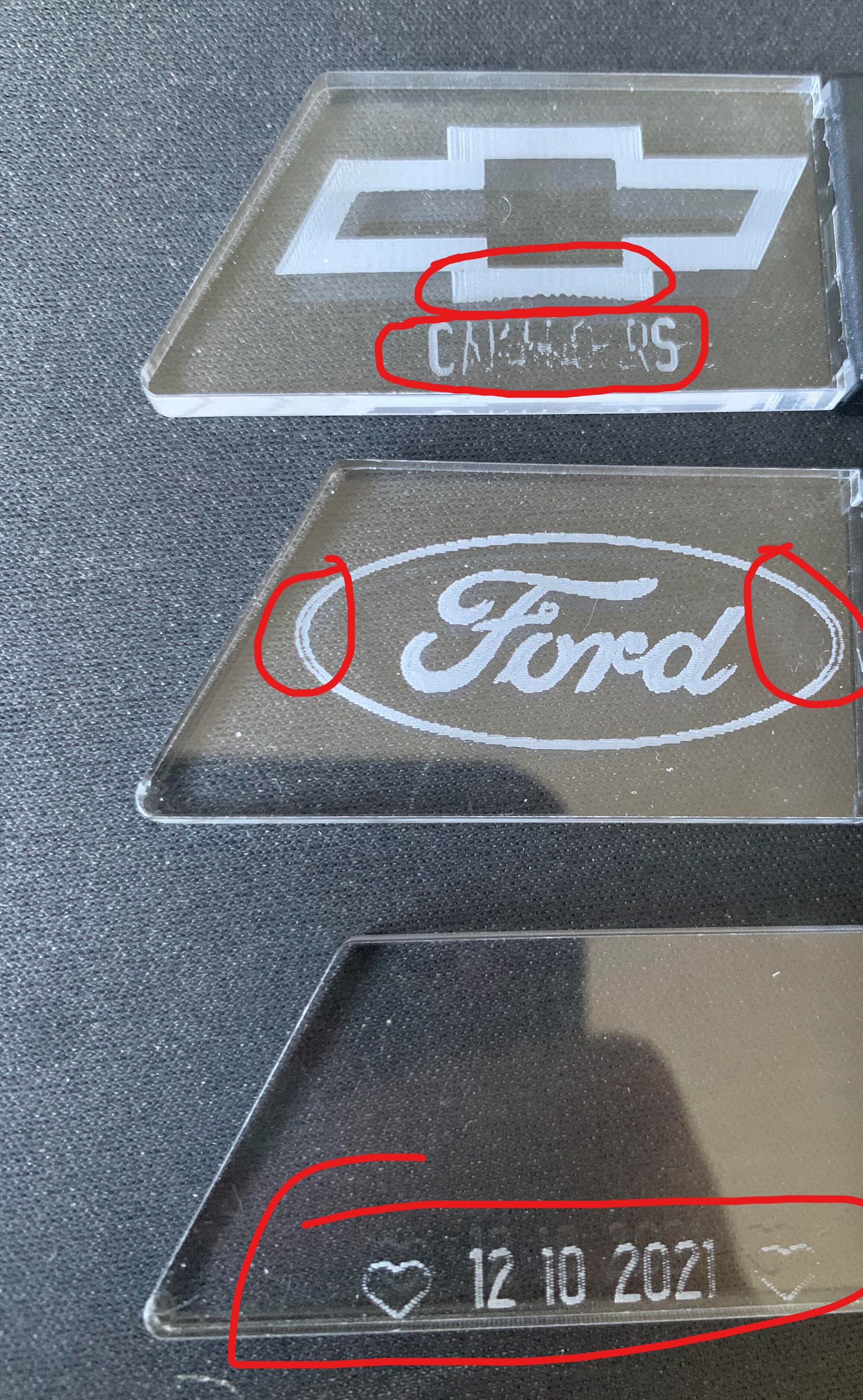
Anyways, I’ve had some issues with engraving fine text with group engraves and other small engravings. Here’s a picture with areas highlighted where the issue is:
In my opinion, your settings are too “optimistic”. A K40 cannot convert these speeds on such a short distance. We have two speeds to work with, the actual laser engraving speed and the transport between the jobs.
Try to reduce your speed and corresponding laser power until it looks proper.
Hi, I’m also curious as to how small these designs are. With a line interval of .08 I would expect to see very minimal lines like the ones quite easily seen on the oval around Ford or maybe its just the image? Im also with @bernd.dk, maybe try and test some more with your settings, faster isn’t always better especially when it comes to quality.
To further reiterate what Bernd and Alex said - and to add, you can’t go wrong doing a power/speed test on any new material, especially on a new machine with a non-standard configuration.
‘K40’ is a general type, not a make or a spec, in the same way ‘3D printer’ is. Typically an A4 bed with a 40W tube, but can have smaller or larger bed and lesser or more powerful tube (but rarely more powerful), a wide range of mirror, lens, air, stepper, drive setups, but all have the same basic PSU and panel - depending on variant. Some are assembled well and with good alignment and tolerances, some aren’t. Treat it like you were doing a QC check. Everything - screws, pinions, earth straps, connectors, belts, gantry, rails (especially those 'shower door white nylon in an aluminium channel).
Assume 30W at the outside for real world power.
Update grbl, if thats what you are running. If you are up to it, completely recompile it on your machine after you have it up and running properly. Use Awesome Tech’s source for a compiled version, not one off the net.
.
Smoothieware on the Mini Gerbil is a sound option, but doesn’t, to my knowledge, support ‘cluster mode’ of LB, which is a pity. It is the best non-DSP firmware for the K40 on STM. It also has the advantage of inline firmware changes, real-time parameter changes right down to pin level.
Jim has a great site with real-world problems and solutions on replacement firmware on K40s.
But, walk first - if you’re happy that the machine is working fine - stops, slop, mirrors, motors, LPSU, earthing, supply, signal wires and that you’ve calibrated your PWM to set the maximum power you want to reach - then make a materials test file.
Bo, it is very well written and fits 100% my journey with my K40, from the start to … I will probably never be finished.
Regarding material tests, I have even made my test discs in different cardboard types. Is it overkill ?, no - I mean, the difference is super clean cut and engraved cardboard versus black-soaked burnt cardboard.
Thanks for the responses. The main reason why I’m pretty sure is a config or some other issue is that when the machine used to be controlled from the M2 board, the machine was able to do the text no problem at 200mm/s with ~15% power (as indicated from the display). If my understanding is correct, setting 15% power in LightBurn would produce the same power in Watts from the laser tube.
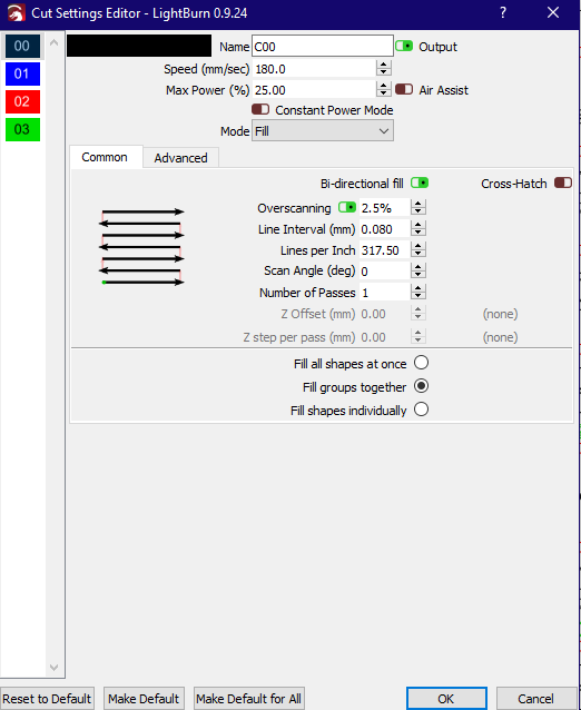
For right now, I have the text and graphics different colors, hence different cut modes. I run the rasters at 200mm/s @ 18% power, where as the text I run at 100mm/s at 20% power, but each letter is done individually with “Fill Shapes Individually” The only reason I don’t like this mode is due to the excessive wear going back and forth over each letter.
I will post back here once I test out new methods for the text. I will most likely end up using the “Fill groups together” mode, as this will reduce the back and forth wear to one string of letters at a time vs. one letter individually.
It sounds like you do not have an ammeter, it is not good, you always have to guess.
Another thing, it is not certain that the values you refer to (from the nanoboard) are the real values, unless you have been able to confirm them in your $$ settings, this also applies to the Mini-gerbil, if your max. speed in the controller is “stuck” you can not get over the values in LightBurn.
(I still think 12000mm / m is not realistic)
No. The M2 and the Mini Gerbil are very different - most obviously, the M2 doesn’t have PWM control - all power management is performed manually, with a dial potentiometer.
You need to calibrate the MG PWM duty cycle output to set your upper limit by (ideally) using a digital multimeter and a test pattern that raises the power 5% a time. You will find a % that corresponds to the maximum mA you want to run your tube at.
The key parameters are:
laser_module_maximum_power - This is the maximum duty cycle that will be applied to the laser. Value is from 0 to 1
laser_module_minimum_power - This duty cycle will be used for travel moves to keep the laser active without actually burning. Useful for some diode setups. Value is from 0 to 1
laser_module_pwm_period - PWM frequency expressed as the period in microseconds
I’m not a fan of implementations that leave the potentiometer dial wired in in a way that allows it to override the controller. It should modulate the PWM signal, not offer raw 5V to the PSU.
The potentiometer should be wired between the PWM pin and the PSU control pin, so it is modulating the controlled signal. Often it is left wired in place, which means you can override the power control coming out of the MG - a recipe for disaster.
For right now, I have the text and graphics different colors, hence different cut modes. I run the rasters at 200mm/s @ 18% power, where as the text I run at 100mm/s at 20% power, but each letter is done individually with “Fill Shapes Individually” The only reason I don’t like this mode is due to the excessive wear going back and forth over each letter.
Forget wear. It’s a non-issue. Speed and accuracy are more important.
Funny enough I do have an ammeter hooked up, but after rebuilding my entire machine I re-wired it backwards so as of right now it’s not usable. Before I was using it just fine, and all I have to do is swap the leads. It’ll take me 3 minutes to fix.
I manually set the maximum X speed to 300mm/s (18000mm / m), so far everything is going OK. I had to up the stepper current a little bit though, after the motors could barely move at 100mm/s
My bad, I mis-spoke. I have the K40 with the digital display on top, which was simply a PWM controller where you could set the percent via the up and down buttons. After testing the PWM values from LightBurn, I found that the tube power output with the MiniGerbil and the original PWM controller from the K40 are the same with the same percentage (most likely same duty cycle).
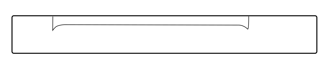
UPDATE: I was taking a look at some of my engravings, and noticed towards every edge the depth of the engraving looked like the following:
**Looking at the material from the side
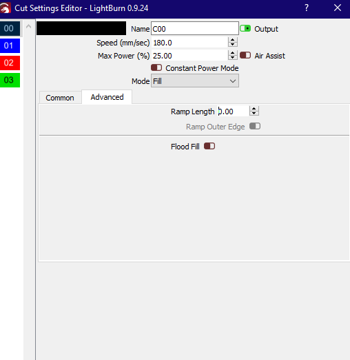
What I came to realize is I had set the X and Y acceleration with relatively low values, I believe around 500-600 (I forget the units, likely mm/s^2 or less-likely mm/m^2). The simple dip towards the edges would only make sense to be directly caused by the acceleration. And, LightBurn has of course thought of this, and created overscanning to allow the head to drift past the end of the part to avoid artifacts like this caused by deceleration. In fact, here’s a post on it:
Low and behold, my over scanning was disabled
I will test this tomorrow as it’s late for me now, but I’m 99.95% sure this is the solution to the problem.