I’m having trouble cutting 3mm ply. I have recently installed a new TR90 laser tube and matching Power supply from Megacold. The TR90 has the Red dot lfindedr already installed on the tube. I must say Megacold were lightning fast on fulfilling my order and the gave a huge discount. The Red dot fonder made aligning the mirrors an absolute breeze. I also upgradr all my mirrors to 25mm and the focus lens to 20mm FL63.5 I used all cloudray mirror hardware and focus lens assembly. These alone made minor adjustment ver easy. Having saiud all that I amd experiencing difficulty in cutting good quality 3mm ply! I cannopt seem to find the correct focal point. As I understand it, that with a 63.5mm lens fitted there is 56mm gap between the flat side of my focus mirror and the end of my focus nozzle. That leaves only 9mm between the nozzle and the plywood. Having set the 9MM I’m having trouble cutting the 3mm plywood. 2 questions, what speed and power would I expect to set the cut? And what is best way/tool to align the focus mirror beam to the surface of the material I.e It’s got to be perfectly vertical but I don’t think it can be. Bed leveling and focus lens mounts are double checke and ok. Can anyone help me please.
Thank you.
You can try doing a ramp test to check your focus.
when you have found the correct focus, measure the distance from the nozzle end to the material surface and make a distance block with this measurement.
I cut 3mm plywood with my 60(55) Watt machine at 25mm/s and approx. 30% power (8…9mA?)
I did that Bernd, but I had to increase power to65% at 10mms before i got any near to cutting.
Your results don’t seem to indicate this to be true. ![]()
- properly working tube
- clean and aligned optics
- proper focus
If you have these three, they work. In your case, I’d suspect one or more of them are not correct.
I have a 40W tube, that I cut 5mm sub flooring (much tougher than 3mm basswood ply) at 12mm/s@65% power. Considering you have almost twice the power available, I’m suspicious of your adhering to the three requirements I previously mentioned.
Did you test the tube for it’s resonance mode? When setting up, ensure that the parts are working as you go. Here’s a quickie on TEM00 resonance or operating mode. Go back and check your results at m1 for the tube operating properly. A new tube should work, but I’ve seen many that do not operate correctly.
When I upgraded my tube, I researched these with builtin led/combiner, the TR series. I had a series of emails with Russ Sadler about them as he seemed to indicate previously they were the best bet for a position indicator. He explained he’s seen too many that were off the actual tube path and suggested I stick with a regular tube, which I did.
@bernd.dk is correct, a ramp test should show you where the proper focus is. I suggest you post a photos of all of your results. We can sometimes see things you may not be aware of.
I’ve never really had a pointer, I realized it was only really useful with acrylic and only when there was a hole in it to take the beam. Not to mention, change lens, change pointer setup… of course with it being generated at the tube, this shouldn’t matter.
Good luck
![]()
Hello Jack,
Thank you for your time taken to answer my question. I used the ‘Red dot’ to align the 3 mirrors. I first fitted the new cloudray 1st mirror mount and maded some new Tube supports. I adjusted the tube sa that the beam fell into the centre of my crosshair taget affixed to the 1st mirroir. All seemed to go quite easily. I then fitted my cross hair tarket to the second mirror and with the mirror furthest away from the 1st the beam was clearly off centre. I contniously move the carriage back and forth making small adjustments either end utill I was happy with the alignment. Next I moved the Target to the 3rd mirror and followed the same sequence as before. Now the vertical focus down through the focal lens was checked for correct alignment. I must admit this is where I get flumixed. I did my best to get a pinpoint hole into my plywood. To achieve focas I carried out a ramp test and found that the ideal setting was approx10mm below the point of the nozzle. I did several test cuts with my 3mm ply and fount that at 10mm and 45% lkow and 45% hi i achieved a good cut. These relts seemed a little bizarre considering I’m using a brand ne tube an a complete set of new mirrors and mounts. Have a look at my phote and please let me know what you think, meanwhile I’m goin to have a look at TEM100 and find out what it means.
Thanks
George
I was actually talking about photos of the ramp test and the target tape scorch marks.
I can’t tell how it’s aligned by a worded description such as you have given. What I though was a good alignment as a novice laser user has changed over time and experience.
I used my tube for about 5 days after it went out of TEM00 resonance, but had to re-align it, at the end a couple times a day as it changed over time.
You have a nice machine and there has to be something simple here we’re missing in the alignment or the tube status.
![]()
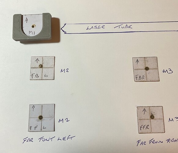
Hello Jack, I had a look at the TEM00 mode and went out and bought some watercolor paper and did some tests. the result are what i show in the pics. I set max laser power to 11 and min power to 10. Max power seems to bee offset a bit. mirror 3 result seems it is getting max power. Go easy on me I’m a mere novice but please let me know what you think. If it’s way way far out then please say so. I’ll do a ramp test tomorrow and upload it.
Best regards
George
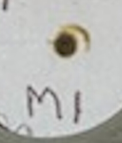
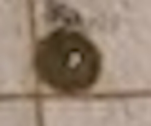
This is pretty indicative of a TEM00 tube failing. Notice the output of your tube at m1.
The crescent shape should not be there…
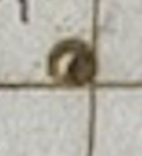
At m2, it’s showing no power in the center area.
M3 has a similar look as if a doughnut.
I think you need to ask the TR manufacturers about this anomaly. I’d say you have a bad tube.
![]()
Thanks Jack,
Megacold have agreed to a replacement tube.
George
New tube arrives tomorrow Jack. And they don’t want the old one back. If I install the new one and align it with the 1st mirror have you got a pic of what is I’d see?
Cheers
George.
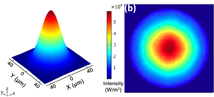
The perfect power distribution is most of it in the center and it drops as it moves outward. It’s normally just a slight shade of the burn that changes from the center moving outward.
This is what you want, 3d on left, and 2d, as you would see it on the target. It’s normally just a shade of the burn that is maximum in the center and moves outward as the power drops.
I need to do this on mine and get an example, but haven’t done it.
Make sense?
![]()
Thanks Jack, As soon as its fitted I’ll do this and send it on.
George
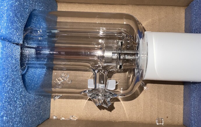
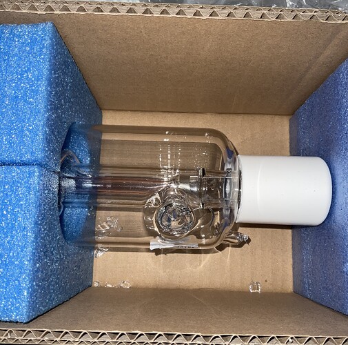
Disaster, new CR90 arrived but was damaged. The water outlet port was broken.
Magatech have been brilliant and will send anpther replacement.
I cannot praise thes guys enough,. If any company needs a lesson on ‘Customer care’ then I’d advise they take a leaf out of Megatech’s book.
Question, so the water outlet is broken, Is there any way that this can be repaired ?
Regards
George
Can you show a picture? I once repaired a tube, the outer cooling ring had fallen off during transport. I used epoxy.
…is there glass in the tube? and if so, can you get it out?
I’ll give it a try, even if it’s just as a backup.
The only fixes I’ve seen are with glass nipples or tips that broke of cleanly
![]()
…most people can handle that.
No, this tube will be a challenge, but I still think I can handle the task.
Considering it’s condition, there is no reason not to try. Ensure you have something there to soak up the coolant if it doesn’t seal…
![]()
