Ultimate Air Assist - Variation

The MK1 version is just the solenoid, some ice maker and pipe fittings and a diode.

The MK2 version just expanded on it.

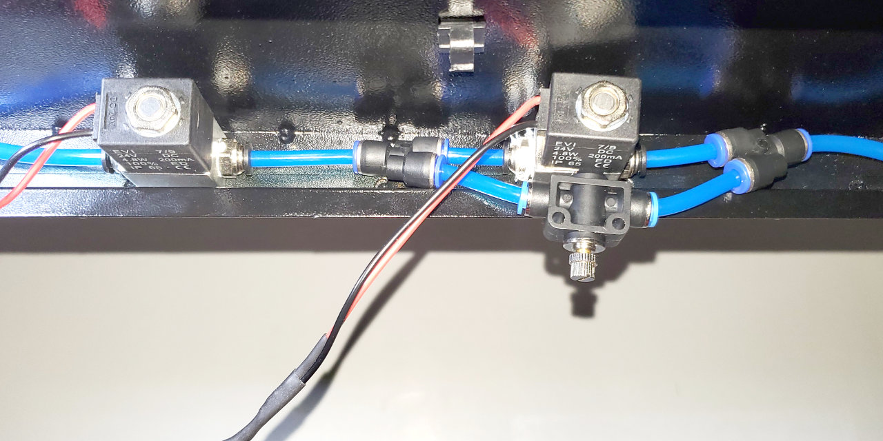
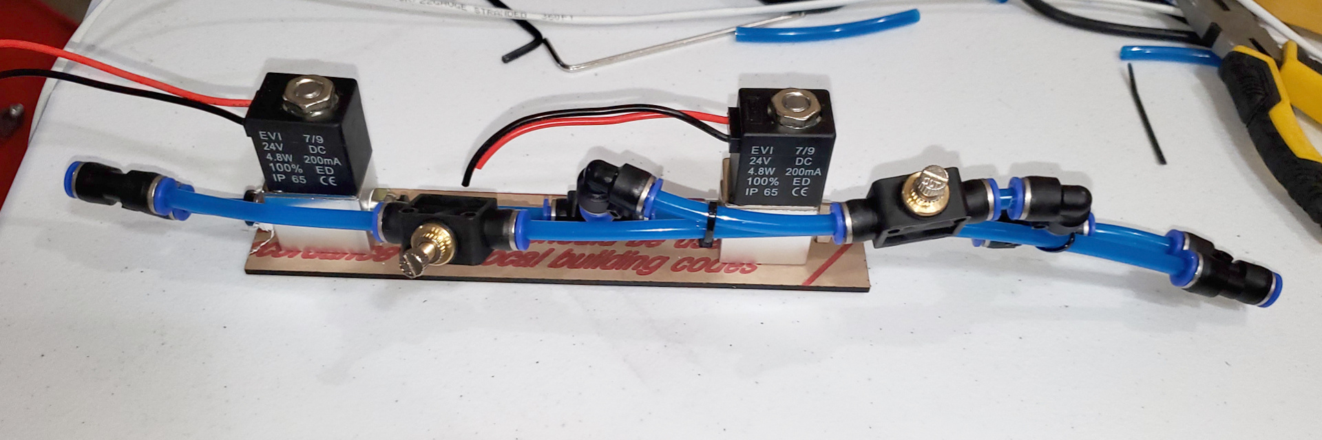
Don’t really have a list. The solenoids are AirTac 3C208NCBT, there are three variations of the 3V208NC depending on your part of the world and pipe thread connection needed. Order correctly.

The pipe / push Tee’s are from WW Grainger, 36W772. They are not on the web site catalog, I had to go to the chat and get one of their people to look them up. Once you have the part number you can order them just like any other fitting.

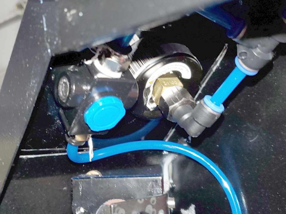
The regulator and gauge combo’s were the smallest and cheapest I could find at Harbor Freight.

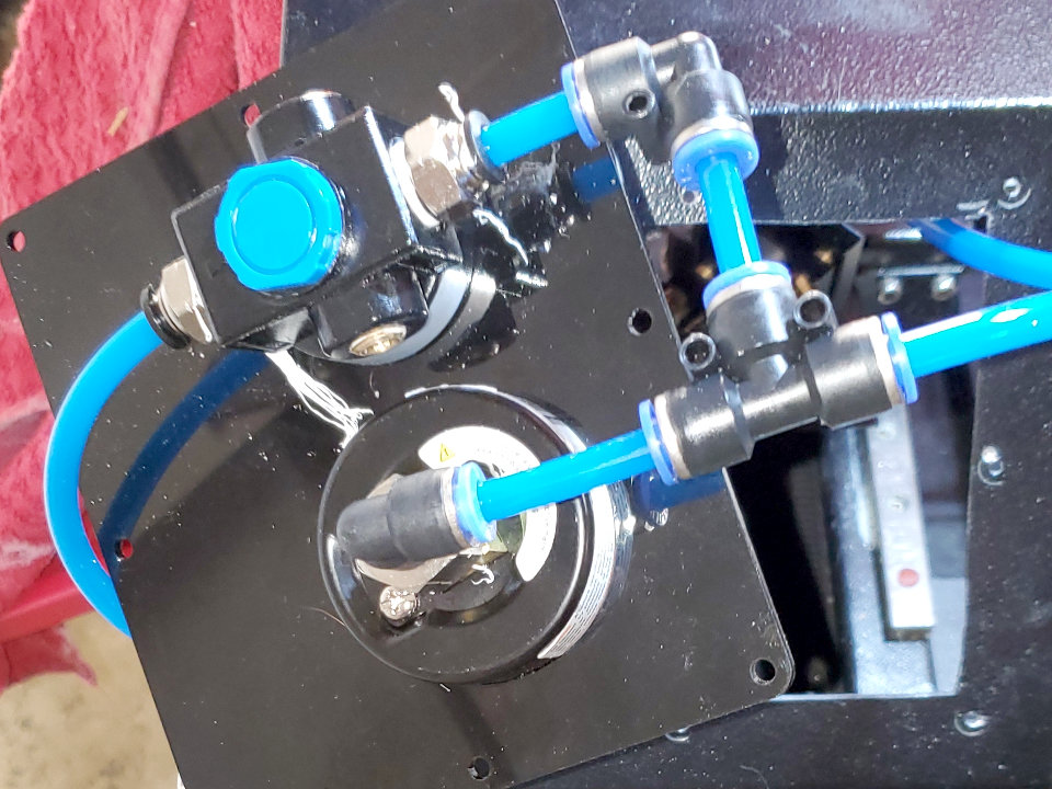
The input 90 degree push to pipe behind the incoming solenoid and the blue bypass valve at the top are ice maker fittings.

The terminal strip was left over from another project, and the wire is thermostat wire. It had enough conductors and different colors to let me keep track of everything.

Pipe plugs for the bypass ports, and a couple of close nipples and teflon tape between regulators and solenoids and that’s about it.

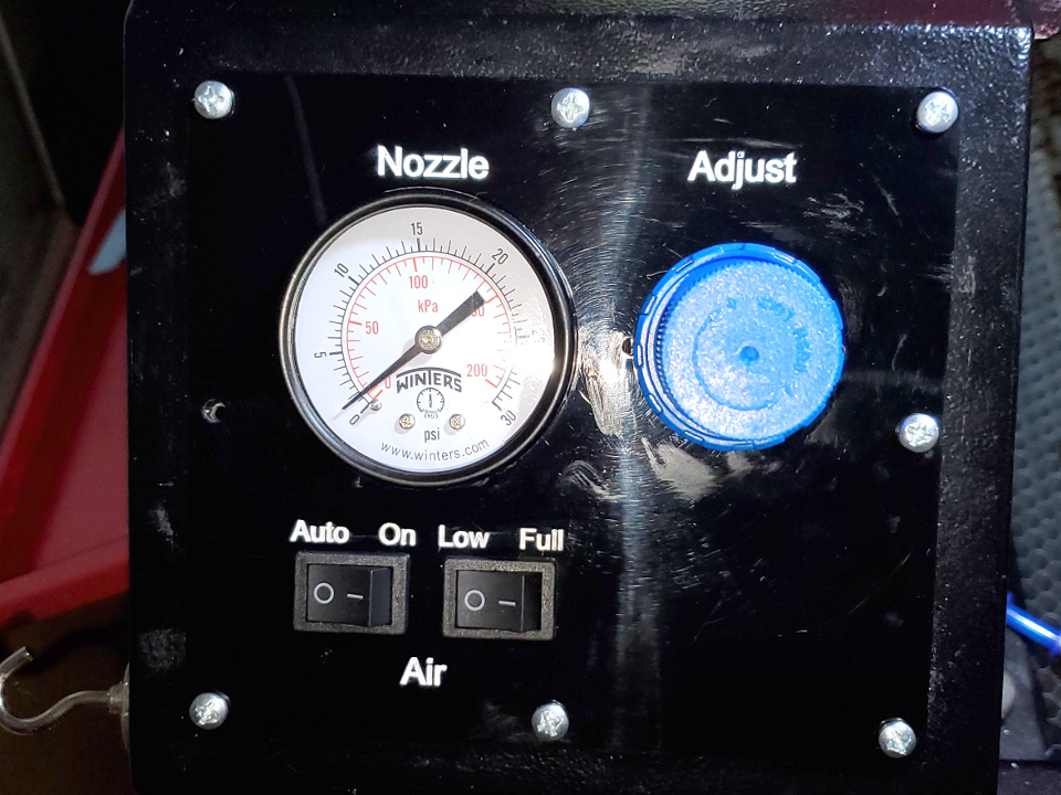
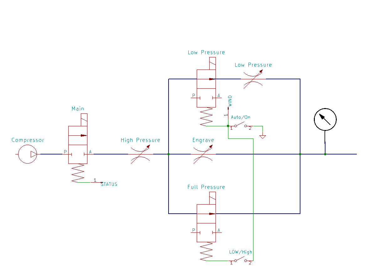
Some items not seen in the picture. The air assist terminal from my controller goes up to a small SPDT rocker switch on my control panel for high / low selection before going back down to feed either of the top two solenoids. I also have a large number 30 psi pressure gauge Tee’d into the line at the machine that sits by the control console, picked it up in the ag sprayer department at Tractor Supply. Each solenoid has a diode across it’s terminals to prevent back feed to the other solenoids, and another between air assist and status to prevent back feed when only the main solenoid is called for.

The solenoids are really the only ‘special’ part in that they will operate with no air pressure, so I can go back to my little diaphragm pump in an emergency. Most air solenoids require a minimum air pressure to operate and would not be able to do that. The bulkhead Tee’s took a bit to track down, but are a fairly common fitting.

Off the top of my head, I would say I have around $125 USD invested, maybe $150. That’s a guess because most of the regular pipe fittings and such came from my spare parts drawers. The wire and terminal strip were both leftovers as well. The terminal strip was part of a package of five twelve position strips I ordered off of Amazon,

I also have a SPST switch as an over ride to the controller air assist.

I’ve been looking at that same California Air Tools compressor, it seems quite nice, but I’ve been trying to figure out if it can generate enough air for longer duration cuts. If you have the air assist set to a higher value, maybe 30psi, and it’s going for 15 or 30 mins or so, does the compressor have to run constantly? Or is it able to run at or below it’s continuous rated 70/30 duty cycle?

Thanks!

The highest I’ve ever run mine is 15 psi. Now granted, that’s a flow pressure, not a static pressure.

I can only guess at the run time available with that compressor. You have the static 4.7 gallon and then the make up rate of the compressor. Setting the high limit at it’s max would gain you a little bit as well. Smaller projects and engraving are minimal air usage, raster or vector, it’s cutting that is the air hog.

How frustratingly interesting.
I didn’t realize that there are other valves available… makes sense now that I think of it.
It might beat the 3 selonoid solution of Dave… frown.

I replaced the slip-fittings for air with a push-connect + quick connect air fitting. I’ve got 90psi up to the regulator now with no leaks. Going to try to put it all together today.

@Dave01 awesome thanks I think I’ve got the gist of it. Can you explain a little bit more of how you wired it all up from solenoid to switch to controller?

Is it blue/yellow to switch, black to wind and white to status?

Time to re-re-do valves. It’s not absolute pressure of ~20psi needed, it’s different pressure needed to operate. So, backto Dave’s design with 2/2 valves that work at 0 differential.

EDIT: It actually works a lot better if the flow restrictor isn’t installed backward. :stuck_out_tongue:

I may still go to a multi-stage selectable pressure like @Dave01, but I can at least finish putting it together.

No, the black is a common ( + on a Ruida controller ). White goes to STATUS, Yellow and Blue go to the high / low switch that feeds from the WIND. No particular reason to use black, it’s just what I had the most of when I made up the solenoid pigtails.

There are diodes on all three solenoids to prevent back feed. Not 100% if I need them after I modified Russ’ set up, but they don’t hurt and they are a few pennies. His basic set up for a solenoid valve and a relay for the compressor is available on Cloudray if you just want to buy the kit. It’s similar to my MK1 set up.

In addition to the ‘automatic’ configuration, I have installed the override as well. I have a switch that goes from the - through a SPST switch to the WIND, and via a diode to the STATUS. If you use a SPDT instead of a SPST you can eliminate the diode but will need a feed to both WIND and STATUS for an override. Since the wires all run up to the console anyway, I also added an LED indicator for air status… until I broke the LED. It will get replaced with the next console version… I stopped numbering them a long time ago.

I have made a few changes since that picture. The four stranded wires braided were replaced by a piece of multi conductor solid thermostat wire. Due to a clearance issue, the tee’s and bypass valve on either side of the low pressure regulator and solenoid were swapped.

If i can get creative and get a few brain cells together I’ll try and do up a wiring diagram. It’s getting those damn brain cells to cooperate some days that’s the hardest.

I made the same mistake on my first valves. Especially when the minimum pressure isn’t in psi. The valve in my pics, is the valve Russ spent many months researching to work with the little compressors as well as the big ones.

And nozzle tip hole WILL make a difference in your pressures. I had a bit of alignment issue, and needed to finish a job. I slapped an old engraving nozzle on, and lost 4 psi in flow pressure.

Update on compressor cycling:
With the gauge set for 12psi flow, the compressor cycles 45 seconds on, 55 seconds off. That’s without an on/off to the air flow and a ~4mm orifice.

While waiting for the new valves to arrive, I at least finished the control panel. I was originally going to place the gauge on the output to the nozzle (to give flow pressure). It would have required another tube coming back to the front. This placement (immediately after the main regulator) will give both static and flow pressure.

The operation will be for the main regulator to control the high-/cut- pressure going straight through one of the valves and the other valve having the low-pressure restrictor in place, then joining together to the nozzle.

This also does open up some extra room for switches, water flow/temperature, whatever. I can also do some labeling when everything in final. The acrylic is strong enough that I’ll probably redo the control panel with it instead of sheet metal.


Awesome, thanks for that compressor cycling info, I really appropriate it :slight_smile:

I didn’t realize that there are other valves available… makes sense now that I think of it.
It might beat the 3 selonoid solution of Dave

I haven’t been able to find a 5/3 valve (A/Off/B) that operates at 0 psi differential, so I ended up with two 0-psi 2/2 (on/off) valves. Going to try to get them installed and wired today.

I’m also changing the layout a little bit:
compressor → regulator → air on/off valve → bypass in parallel to 2nd valve

This will allow the gauge to show both static and flow pressure depending on what state the laser is in. Having a main valve in series gives less connections to leak when everything is off. When the main valve (STATUS) is on, and the bypass valve is closed, air will flow the parallel, low-pressure, path around the 2nd valve. When the bypass valve (WIND) is open, it will be full pressure through the valve.

I may end up with a 3rd valve, in between the compressor and the regulator, wired straight to 24V. That would reduce the number of opportunities for air leaking when I’m not using the laser. compressor → main valve → regulator → air on/off → bypass/high-pressure.

EDIT: This change also means that I don’t need a helper relay to switch between bypass and high-pressure. STATUS/bypass and WIND/high-pressure can be on at the same time without any ill-effect. I’ve added snubber diodes to the solenoids and extended the wiring. I now need to drill for and mount the valves and run the wiring.

1 Like

Valves test-fit and tubing cut. The valves need to still be screwed down. The layout allows the low-pressure valve to be adjusted if desired, but normally out-of-sight, out-of-mind. Everything tucked up nicely out of the way of the door latch.

Wiring, tomorrow…

Ive got the 2 pump, one motor, 5 gallon version. It would come on about every 5-8 minutes when using it for air assist.

If I tried that again, I would go for a bigger tank. At least 30 gallon, if not more. You can add capacity by adding on one of those “spare air” tanks as a test if needed. People usually have them in the garage for filling tires. THey are also handy for changing the fittings to larger than normal and having yourself a booster for things like impact wrenches that use a high volume of air really quick, with just some good fittings and a section of high flowing hose.

I was already planning on getting an additional 5 or 8 gallon tank, if needed. I’m already consuming a large chunk of a 2-car garage with “stuff”, so I’m trying to be careful with taking up too much room. :slight_smile: This is the 1hp version, so it won’t have any trouble filling the main + extra tank in a reasonable time.

Since it will primarily be on bypass (and only when a job is active) and the high-pressure is only for cutting, I’m fairly confident that the original tank will be enough. Keep in mind that I had it on continuous flow at a much higher pressure than I would normally be using.

“Done! (and it works :slight_smile: )”

Now I need to tune the bypass pressure and figure what what pressure works best for various cuts.

I’ll probably re-purpose the power relay I was using for the aquarium pump and have it as a power outlet for “on when the chassis is on” until I find another use for it.

I somehow managed to detour some updates into PM. Seeing if I can recover…

I hadn’t planned on going to high/low pressure, but… Well, I did. Also done without any relays and by using some SPST switches I already had rather than SPDT.

I put the main on/off air before the regulator because that is a single connection to control bleed-down leaks instead of four. The high/low switch just adds the high pressure (full open) bypass to the low pressure path. I moved the air gauge to the nozzle instead of after the regulator because it’s more indicative of actual pressure instead of the back-pressure that the rest of the system gives. I added scrubber diodes to all the solenoids. The 24V power path isn’t shown.

I may end up put water flow/temperature in the remaining space.

I’ve got everything lined up. Just need to re-assemble; although the pressure gauge won’t go to zero so I need to replace it.


1 Like

2nd unrolling of PM to public. :slight_smile:

I can eventually learn… Having redesigned the whole setup to be off/bypass/low/full, I got tired of scraping my knuckles and not being able to see up in the guts of the chassis where I was trying to set everything up.

So, “hey, why not set up a jig and do everything where you can get to it and then put it in place when you’re done?”

With the main (not pictured) valve open (via STATUS), the only flow is via the bypass restrictor (left). Open the “low pressure” valve (via WIND), on the left, and the flow can go through the higher pressure restrictor on the right. Open up the right hand valve with the hi/lo switch and there is a full pressure path all the way through.

I had considered running everything more in parallel, but the tubing layout works better this way.

1 Like

All done. I ended up with a parallel setup across bypass/low/full because it was one less diode and easier wiring. 2 diodes may not be needed, they just prevent pulling STATUS and WIND to ground via the override. The other one prevents STATUS from backfeeding into WIND because the manual override shares a ground. I also ended up with a SPDT switch for high/low.

The front panel selects full/low and can also override bypass/low/full (to adjust pressure without axis movement or laser active.

Done! (and it works as intended:))

This topic was automatically closed 30 days after the last reply. New replies are no longer allowed.