Moisture separator - I have seen guys use a small tank with a drain on the bottom. Takes more space than a little unit that’s designed to do it, but it works.
I’ll see your drain tank and raise you a refrigerated air dryer. ![]()
LOL, it’s hell being a consummate tinkerer isn’t it? We just can’t leave well enough alone. have to tweak it to our desires.
Here’s where to start… 
https://www.coleparmer.com/i/masterflex-proportioning-solenoid-valve-1-4-od-0-30vdc-0-040/9865012
Find one that does PWM and is about 1/10 the cost…
AirTac 3V2 series.
The nozzle on our thunder laser was out of shape, and undersized. Probably was losing 15% power because of it. Not to mention meh engraving.
I did see a notable difference in a test cut with 3mm birch with air pump vs compressor dialed down to 30psi. So, at some point “more than the air pump and less than 90 psi”, pressure makes a difference.
Im usually cutting birch on a 100w laser, and higher pressure didnt seem to do much for cut quality or speed. Even with a water separator and 2 silica dryers, we were getting moisture at the end, which is why I decided to go back. Once i get our garage here at the shop plumbed for air and maybe a dryer for paint guns, I’ll give it another try (we are going to add an air run up to the graphics room for airbrushing and other assorted needs, plus that little bit of added capacity).
By all means, experiment. One of these days i want to play around with cutting copper, which could be done on a smaller laser running O2. Id also like to see what running argon or CO2 through from a welding tank does with materials. I know on the larger machines its absolutely needed to cut metal, but what could a smaller machine do with it? (I have a couple friends with kilowatt fiber machines that make parts for us… so jealous)
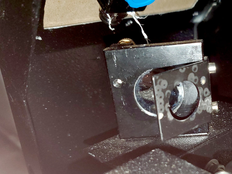
I just found out that the air assist connection to the tubing going to the nozzle is literally just a slip fit, and that it can’t hold 90 psi.  I turned the regulator down to zero and a few seconds later, pop/whoosh.
My incoming to the ploy ice maker lines and fittings is 60 psi. the high and low are 15 psi for MDF and 5 psi for acrylic. The bypass for engraving will barely bubble water, just enough to have positive pressure in the nozzle.
Mockup for the front panel. I may actually make it out of acrylic rather than sheet metal since it’s so much easier to work with. Also, will put some kind of sheet metal shield since the laser can go a bit wild when aligning from scratch.
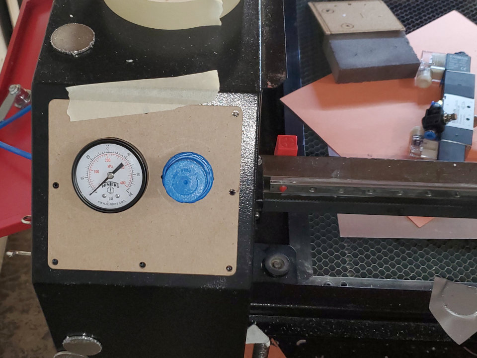
I plan on bringing the main air in from the bottom, out the top and back to the rear where I’ll have the valve, and the low-pressure regulator. Tee it and bring the nozzle supply back up where the original is and the other side of the tee coming back along the top for the gauge. This should avoid any interference with the drag chain carrier.
I’m left with enough room to clear the gantry and there may be room to put water flow/temperature there, too.
Wish I had that much room on my left side. With the gantry fully forward, I have less than an inch between the top of the #2 mirror and the angle. But it also looks like you have a bit of a different arrangement. My X limit and stepper is on the right.
The left side has the 1st/2nd mirror, the X stepper and the drag chain. I was actually worried I wouldn’t be able to fit it in there with the mirror. It’s still tight, but no fear of mechanical interference. I could probably gain a little more room by moving the gauge and regulator up, but I wanted to make sure I had plenty of room for bend radius. I might be able to gain even more if I go to elbows on the regulator instead of straight connectors. The X-limit is on the left of the gantry, and the Y-limit is at the right/rear.
The right side was mostly empty, and I used that for the 48V PSU to the steppers. The right/front/top is the Ruida controller, and the right/front/front are my re-done control panel and additional switches.
Ah, for me all my electrical / electronics is on the right. I have the #2 mirror and X bearing on the left, and that’s it. Of course the manufacturer saw fit to shave that side down to minimal clearance. If the #2 mirror wasn’t so close. I could actually get about an extra 10mm of front bed space, but the mirror would hit the angle if I did… I have contemplated cutting it and bending it up straight for clearance, but not sure if it’s worth the trouble for an extra 10mm.
Putting more energy into the planning and piecing together for the eventual custom build.Take my list of over three dozen mods, and incorporate them into a machine capable of holding a full sheet of wood. I’ve pretty much decided on putting the tube on the gantry, I just haven’t decided between mounting the laser PSU there as well, or picking up a long chunk of HV wire and putting it in a separate cable chain.
I have access to a fair amount of 3A NEMA 23 steppers, so the larger gantry and tube would not be a problem, just not sure about the added 6 pounds of weight of the PSU. I think a gear reduction on the Y axis would compensate, but I’m not positive and don’t know enough about the motor torques to work it out…
Gear trains are pretty straight forward. speed/torque are inversely proportional. 2x speed = 1/2 torque. 1/2 speed = 2x torque (minus gear train losses).
On a purely whimsical basis, I’ve wondered about multiple tubes, combiners, splitters, and mirrors to manage large tables without having the tube/PSU on the gantry, but I think alignment would be… interesting, if even possible. Then there is also the possibility of a vertical tube in the center of the workspace and using polar vs cartesian coordinates… ![]()
I’m looking at a machine that will hold a 4’ x 8’ sheet in it’s cutting bed. a flat version of this in aluminum. Tube on gantry is not all that new in the larger machines, I’m just not sure about the added weight of the PSU.with my 3A NEMA 23’s. The tube and water will be enough I’m afraid I’ll be near my limit on the Y drive. But again, it will be an experiment as I lack the knowledge to calculate things properly. The only saving grace is that it would be cutting and vector engraving only, no raster.
I have a bunch of them for free, and my understanding is I can wire them in series linked to the same shaft for more power / torque. I’ve just not had the chance to play around with it. I could always order a NEMA 34, but if I can make the free NEMA 23’s work, then so be it.
IMO, try a single 23 and see if it’s good enough. If not, order a 34 (or a bigger 23 to match the existing mount). Trying to synchronize, tune, and align multiple 23s is just another headache.
That’s what I’m thinking. Did a bit of research, and the 23’s and 24’s are almost identical in mounts, just different depths for the motor. Don’t know why, but the double shaft motors seem to have a higher rating than the single.
In that vid, they used 34’s and 24’s, but they were also moving a plywood gantry. I know the 23 would be more than adequate for the head movement, especially since I’ve made a modified sliding mount from acrylic and aluminum and have switched to Russ’ MK2 lightweight head. Going aluminum and 3D printed on the gantry takes most of the weight out, so it’s the tube, which is almost nothing, the water in the tube nad cable chain, that’s a bit, and then the 6# of PSU, the heavyweight of the bunch. I’m thinking of gear reduction any way. The set up on my current machine uses a 15 / 36 reduction set up with 2A motors. I could go 15 / 72 with the 3A and see what happens.
The again I could find a deal on about 20’ of HV wire and not worry about it. Had a guy suggest spark plug wire, but I have no idea of the specifications on either one, but I know the spark plug wire is in 30’ coils for rewiring the old cars with custom layouts. Used to have some at one time, but it’s long gone.
I’ve been realigning my mirrors for over two hours tonight… I dream of a gantry mounted tube or 150w diode. I’m so tired of mirrors and lasers right now.
Yeah. I hope you aren’t tunnel visioned on ‘centered’. Parallel and close to center is good unless you have small mirrors. The only place center makes a difference is down the lens tube. I hit my #3 about 2.5mm high to hit the center of the lens tube.
I fought my #1 to #2 for a long time. Finally made a target that hangs on the #2 adjustment screws. the target is dead center of the mirrors for consistency, and no forgetting which way I need to adjust between target swaps. Once I get it close, I hang a target on the #3 to give the #1 to #2 a final tweak, the extra distance with the #3 at far end of travel is like an amplifier for errors. It’s made a world of difference in getting and keeping my #1 to #2 alignment.
You’re going to chuckle at this. Did some more searching on the HV wire. Guess what uses the same wire as the lasers for HV? Neon signs.
@Dave01
Do you happen to have a parts list and instructions for your air setup? Based on your pictures, your setup looks perfect for what I need!