I upgraded my Blue/Grey 50W Chinese laser (Ruida) to 70w tube and 80w power supply. Its more powerful for sure, but I am having trouble with clean fill cuts, I did a material test and it burned out the sides of test holes. I use the machine to cut 3mm holes often, so the squares I set to 3mm. As you can see in the picture it burned outside the sides of the fill area. Any suggestions on what I need to change? Thanks.
Also, where it was supposed to cut text it just did garbles lines.
are you sure it is in focus? and if it is, too much power or too high resolution
Because we do not know the settings, it’s impossible to be more specific, but less power and more speed seems in order.
In round numbers, my 60 W machine cuts 3 mm plywood with 60% power at 20 mm/s.
That is likely too small for cutting tests, because the laser cannot reach whatever speeds you set over 3 mm. Doing the test with 10 mm squares may be more informative.
Excluding clean, as far as I know, there’s no such thing as a fill cut, that I know of. Either you’re filling the blocks or cutting them out.
How much larger in diameter was the 70W tube compared to the supposedly 50W that was supplied? In this area, they change diameters as the wattage increases in this range fairly quick.
When you changed out the supply, did you just swap connectors from the older lps to the new lps?
I’m trying to determine if you actually re-wired anything.
Without information, such as acceleration (both axes) and speeds settings, we can’t help you much here.
If you’re cutting holes you need to see if the speed is correct by applying the acceleration to the sizes.
If you are using fill, the Ruida will apply overscan to reach the user set speed using a scan mode, but it can’t cutting a vector.
I noticed this also, but without more information, I’m clueless as to what to check. It doesn’t look right. This is why I asked about the lps swap.
![]()
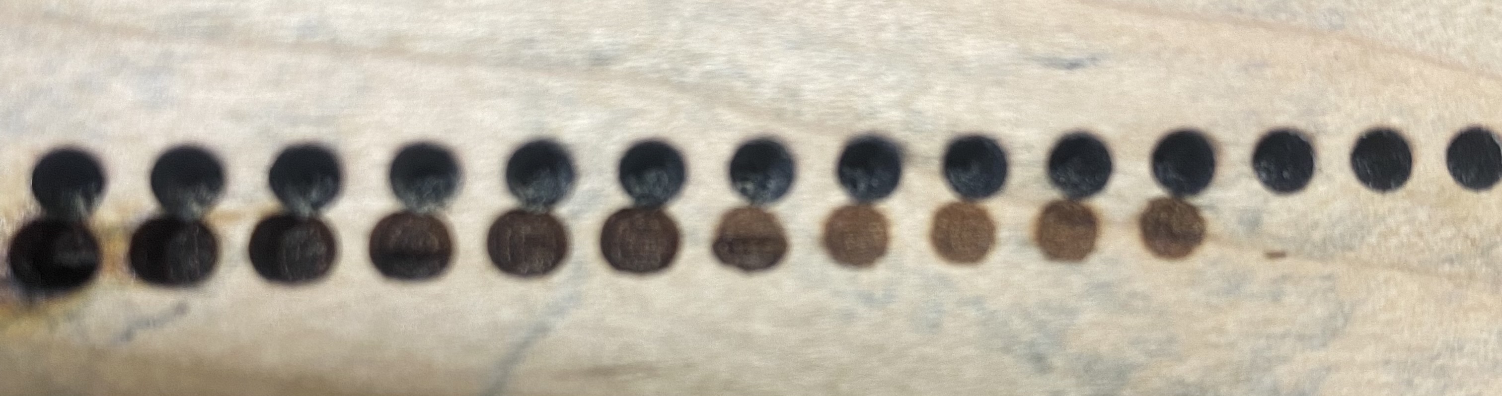
Thank you everyone for the replies. @ednisley and @jkwilborn I use the term fill cut as I am cutting holes with the fill setting to cut (drill) holes for cribbage boards. With my old 50w (if it was even that) I could get nice clean holes. with my new setup it cuts deep, but the holes are oblong, unless super low power, as in the picture.
I know its a bit blurry, but the top row was with the old setup nice round holes, the bottom playing with different power settings, higher power larger oval, low power circle.
The wiring was pretty much plug and play.
Yes, the new tube is much bigger.
I am wondering if its something to do with acceleration or overscan.
Also here is what was supposed to be cut in the first picture.
Thank you for taking the time to help.
-T
Given that you did not change any moving parts, that seems very unlikely.
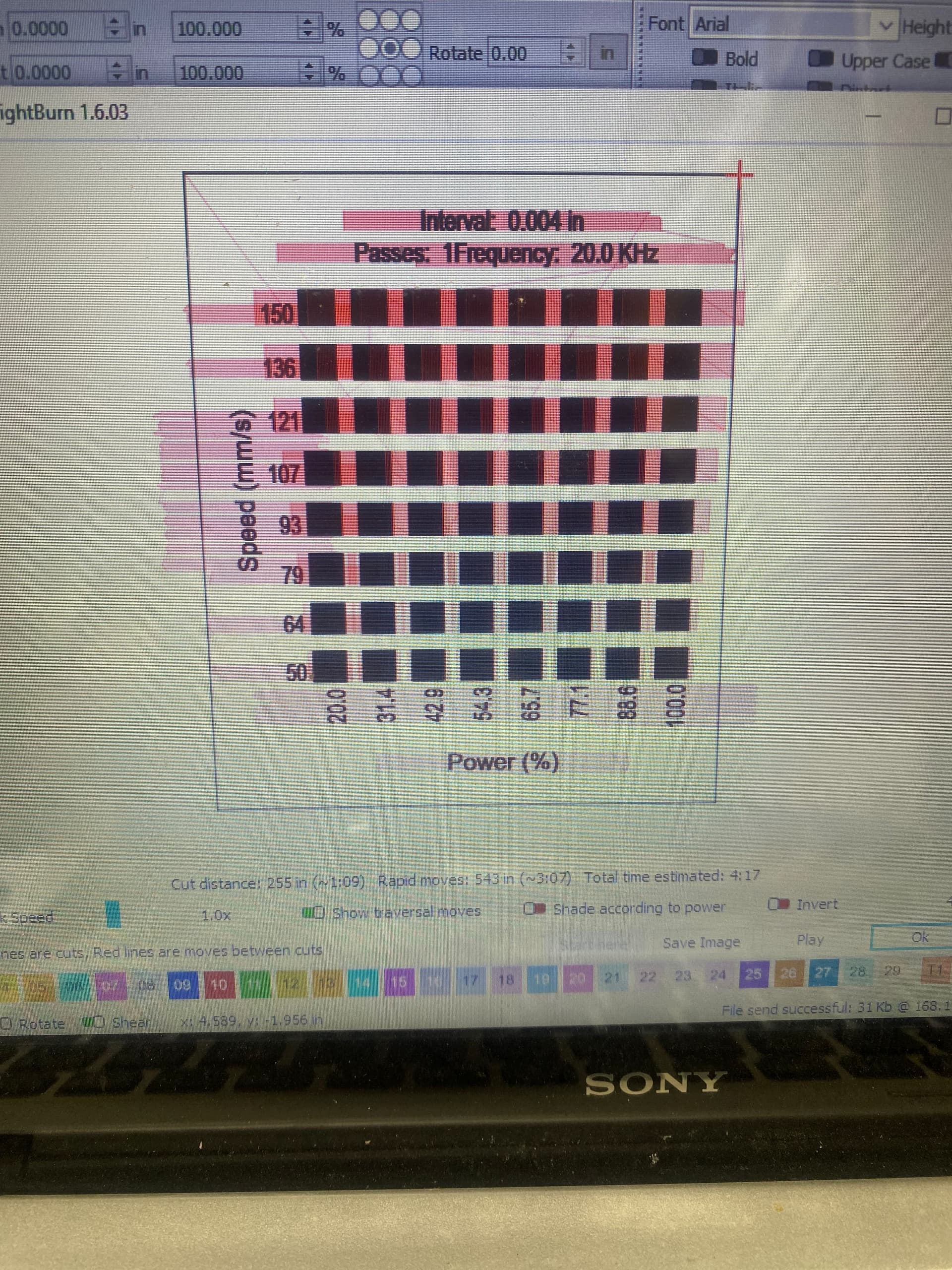
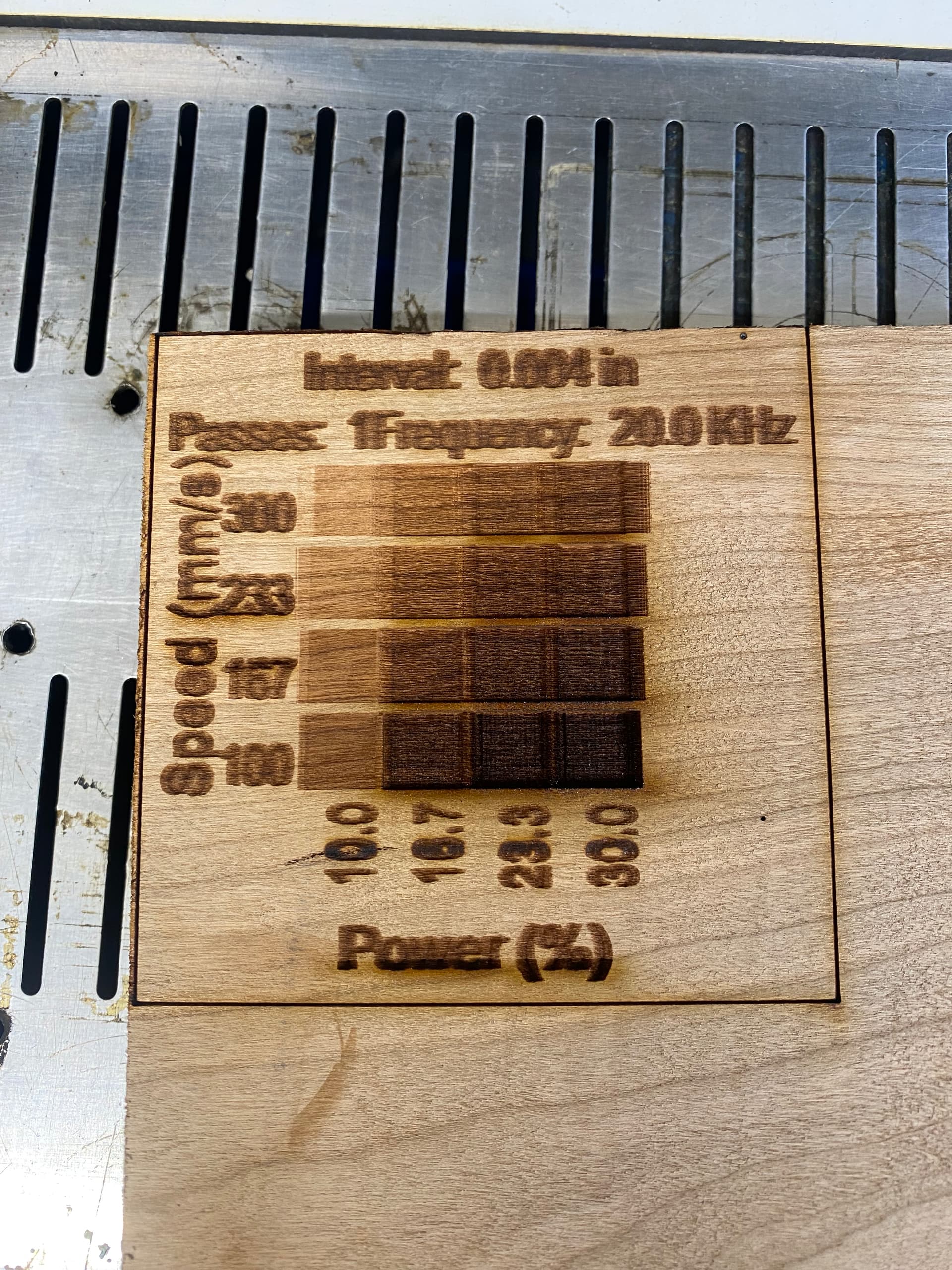
Given that you have a much higher power tube, the speeds seem very low and the power very high for any type of engraving.
Run that again with powers from 10% to 30% and speeds from 100 to 400 mm/s. If those results look better, then you can fine-tune for digging holes.
However, have you verified the mirror alignment with the new tube in place?
Nightmare scenario: what does the scorch look like at the entrance to Mirror 1? If it’s not a nice round / even / pleasant spot, then you may have gotten a bad tube.
Thanks, I will try lower speed higher settings. I will double check mirror 1, at mirror 2 its a nice doughnut.
If this is the case, your tube is shot and needs to be replaced … sorry.
![]()
Left test is at mirror 1 - 11% power for 2 second pulse. Right is mirror 3 - 11% power 2 second pulse.
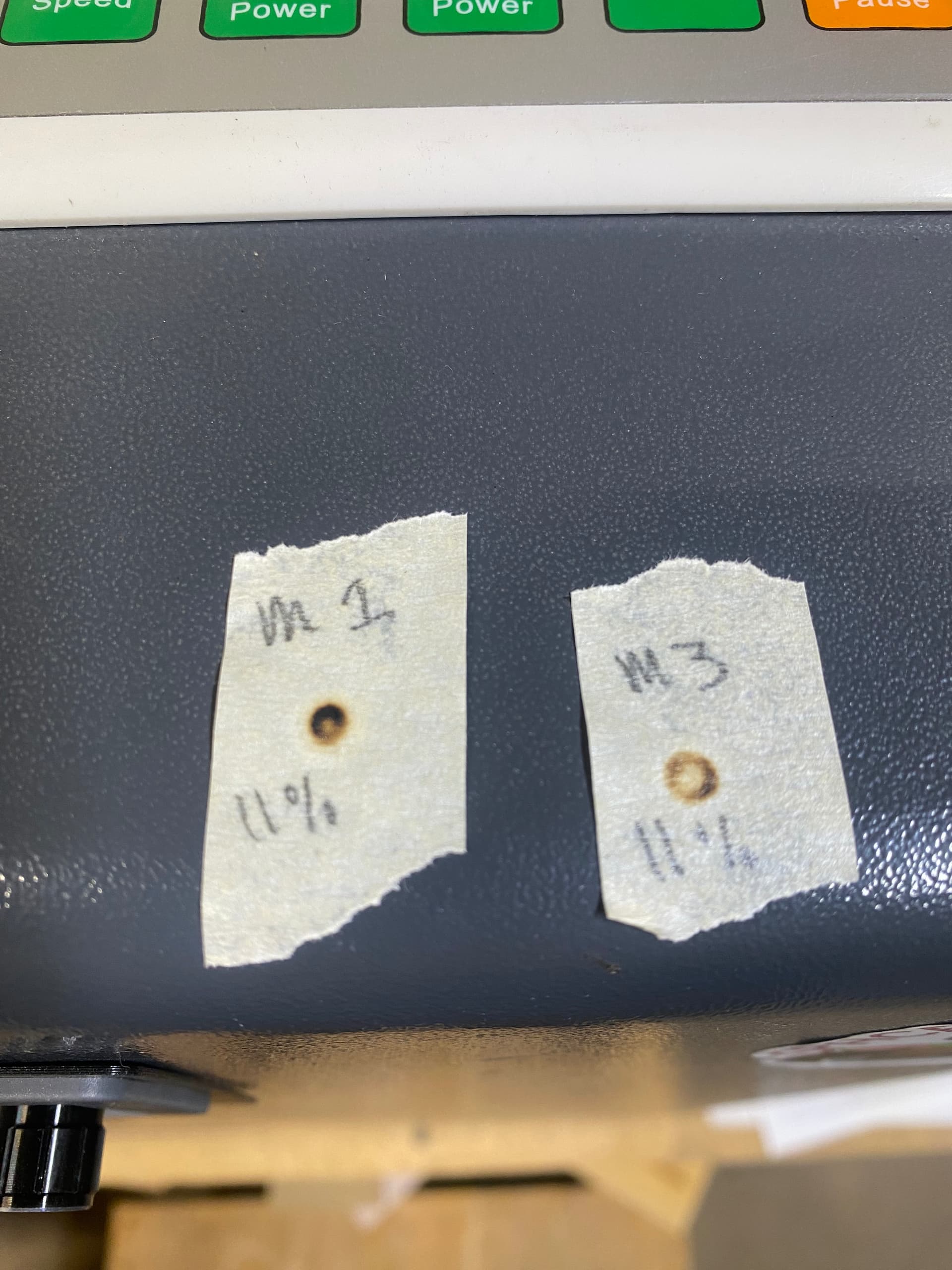
As @jkwilborn points out, that tube is defective.
These discussions cover the details:
Unfortunately, there is no way to repair a defective tube. If it’s under warranty, you should be able to get another one.
Thank you for all that, I am reaching out to cloudray about it. It the meantime can you help me understand how a bad tube would cause it to cut outside the lines like that? It seems it starts to engrave at a lower power before the box, engraves the box at the desired power, then lower power on the other side of the box.
Seems the power is on during acceleration and deceleration.
Thank you again for your time and insights.
The whole point of a laser is to produce a coherent beam of light with a good energy profile across its diameter, so the focus lens can concentrate that energy into a very small spot.
The rings scorched into the tape targets show the energy does not have the right profile, so the lens can’t turn it into a spot. What, exactly, the lens can do with a beam shaped like a ring could be calculated / simulated / whatever, but the energy definitely won’t become the very small spot required to work properly.
How the tube gases behaves while the controller is ramping the current up at the start and down at the end of each vector is whole 'nother simulation, but it’s not surprising it doesn’t behave like a good tube.
It’s a wonder this stuff works as well as it does when it’s working well! ![]()
Thank you all, I will see about getting the tube replaced.
The mfg had me pulse the laser for 5 soconds at the end of the tube with some clear acrylic, it burned a conical shape with the center being deeper cut. So they said the tube is good.
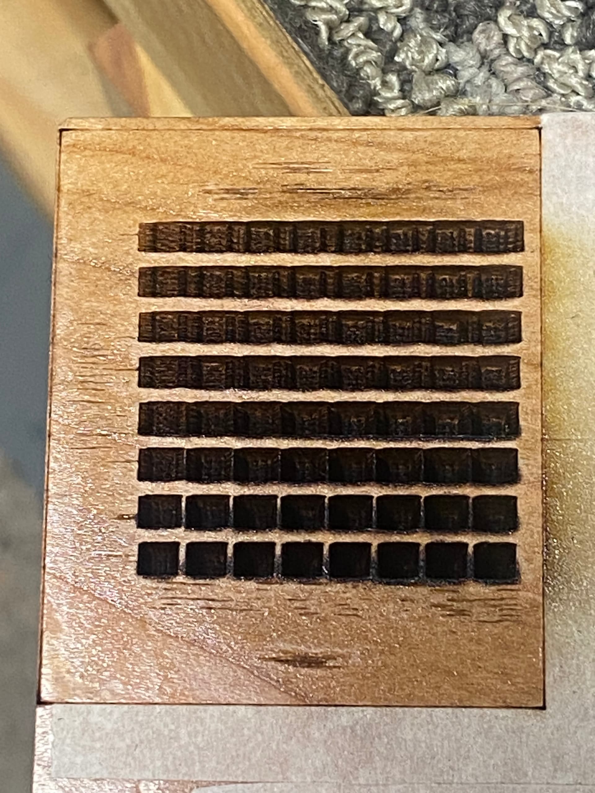
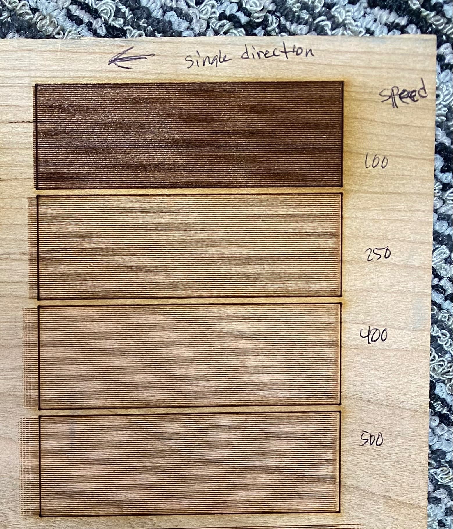
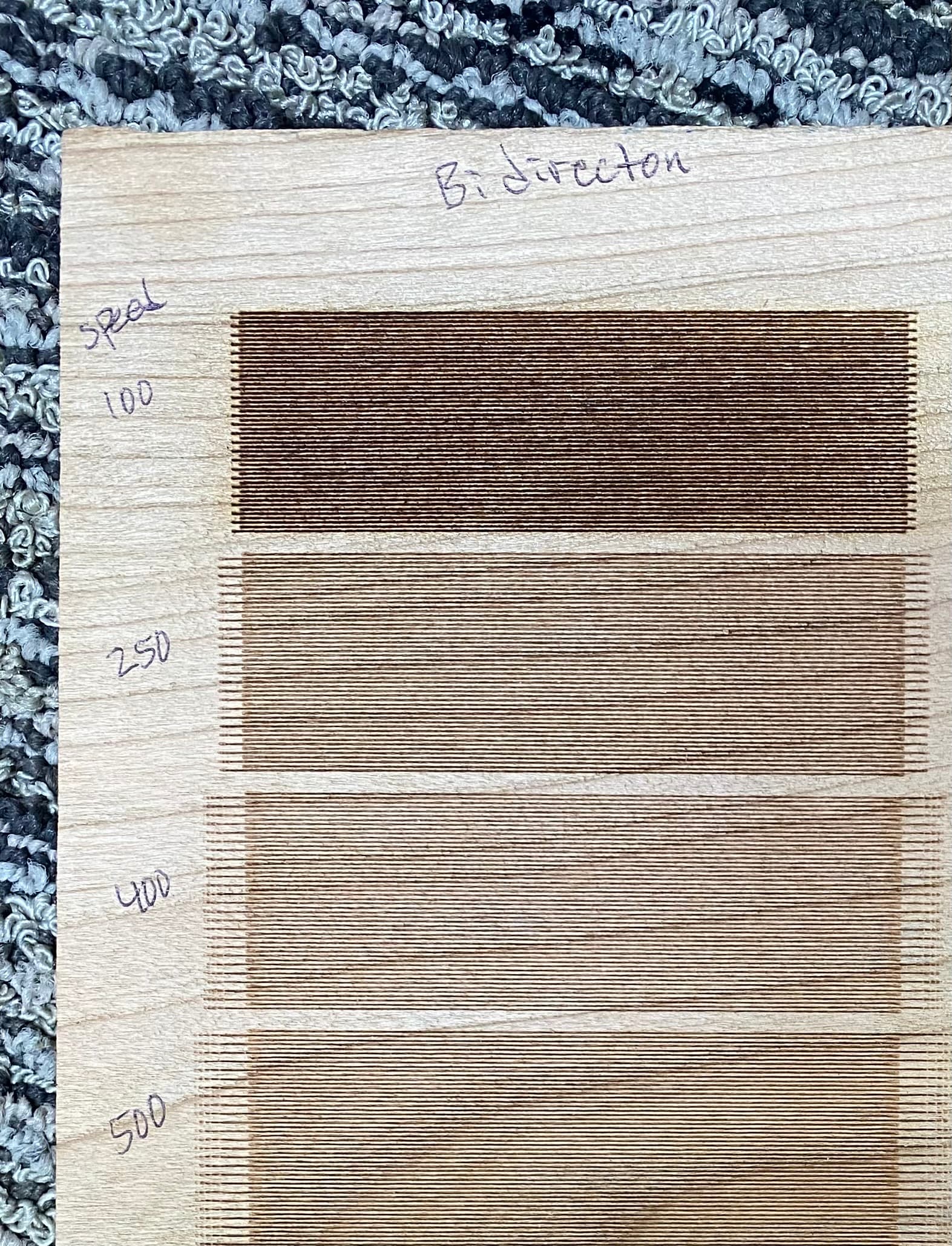
I still dont know why the tube is not tuning on and off properly, if you look at these it comes in just a tiny bit late, but keeps burning way past the line based on speed. Any thoughts? Or is this another indication of a bad tube?
Thank you.
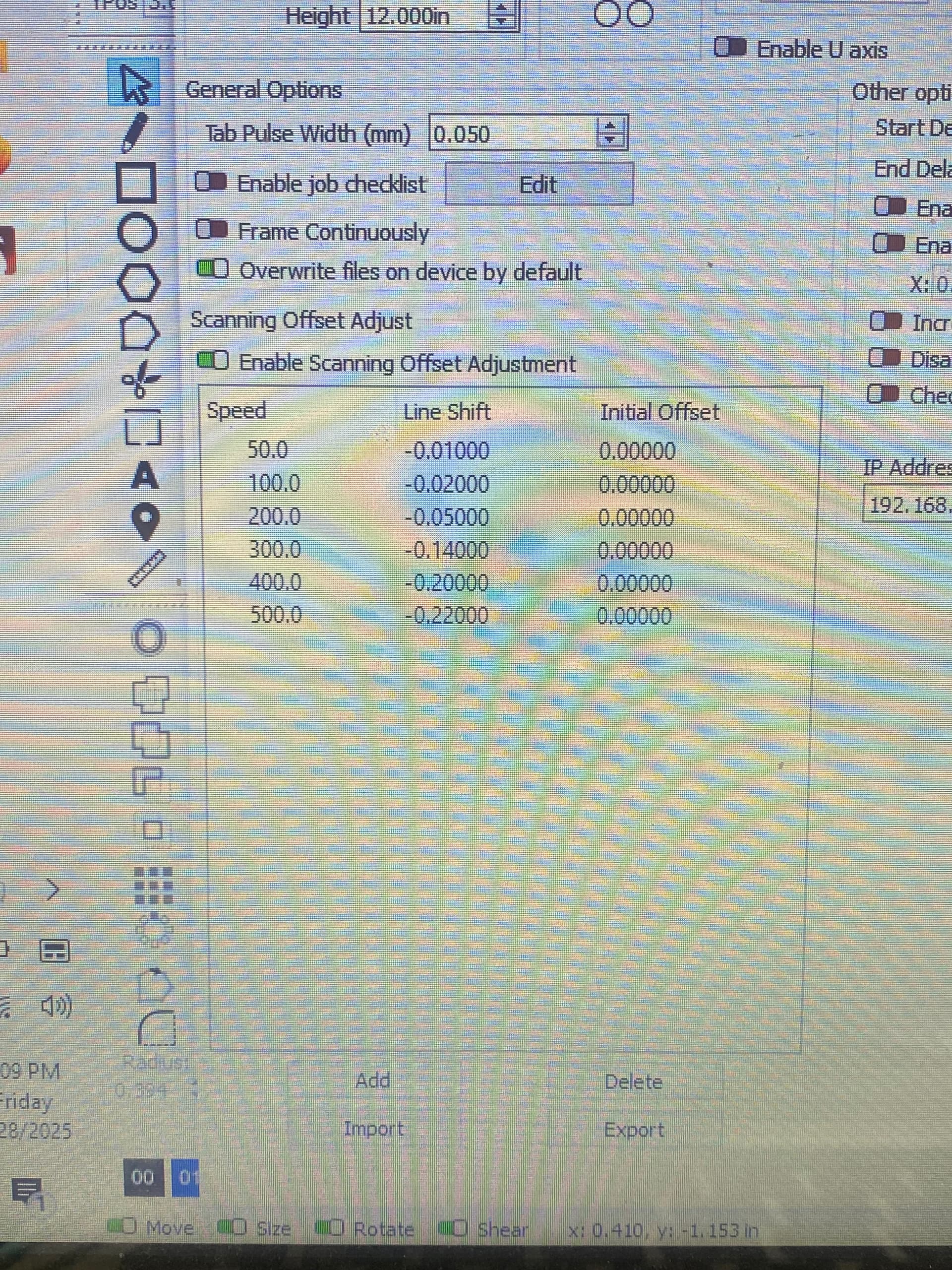
That’s what the Scanning Offset Adjustment is for. The value you enter into the offset table is half the distance between the line ends; a measuring magnifier makes those measurements trivially easy.
[sarcasm] Well, that’s a good way to make you Go Away, which seem the primary goal of Customer Disservice Centers these days. [/sarcasm]
Your test scorches show the tube is not resonating correctly, but convincing them of that may be impossible.
After you have realigned the mirrors, measured & set the Scanning Offset Adjustment values, done enough Material Tests to find the best speed / power combinations for your projects, and generally gotten the machine working as well you can, you must decide whether it’s good enough for your purposes. If not, and if you cannot convince the seller to replace the tube, you’re looking at buying another tube.
I changed the scanning offset values, with no change to the primary problem. For fun I reversed the values and saw a change (made it much worse).
Can you suggest the best terminoligy to use when dealing with Cloudrays customer service? Are there any other test I can do on the tube that will refute the clear acrylic test they asked for?
Thank you again @ednisley I am very grateful for your time.
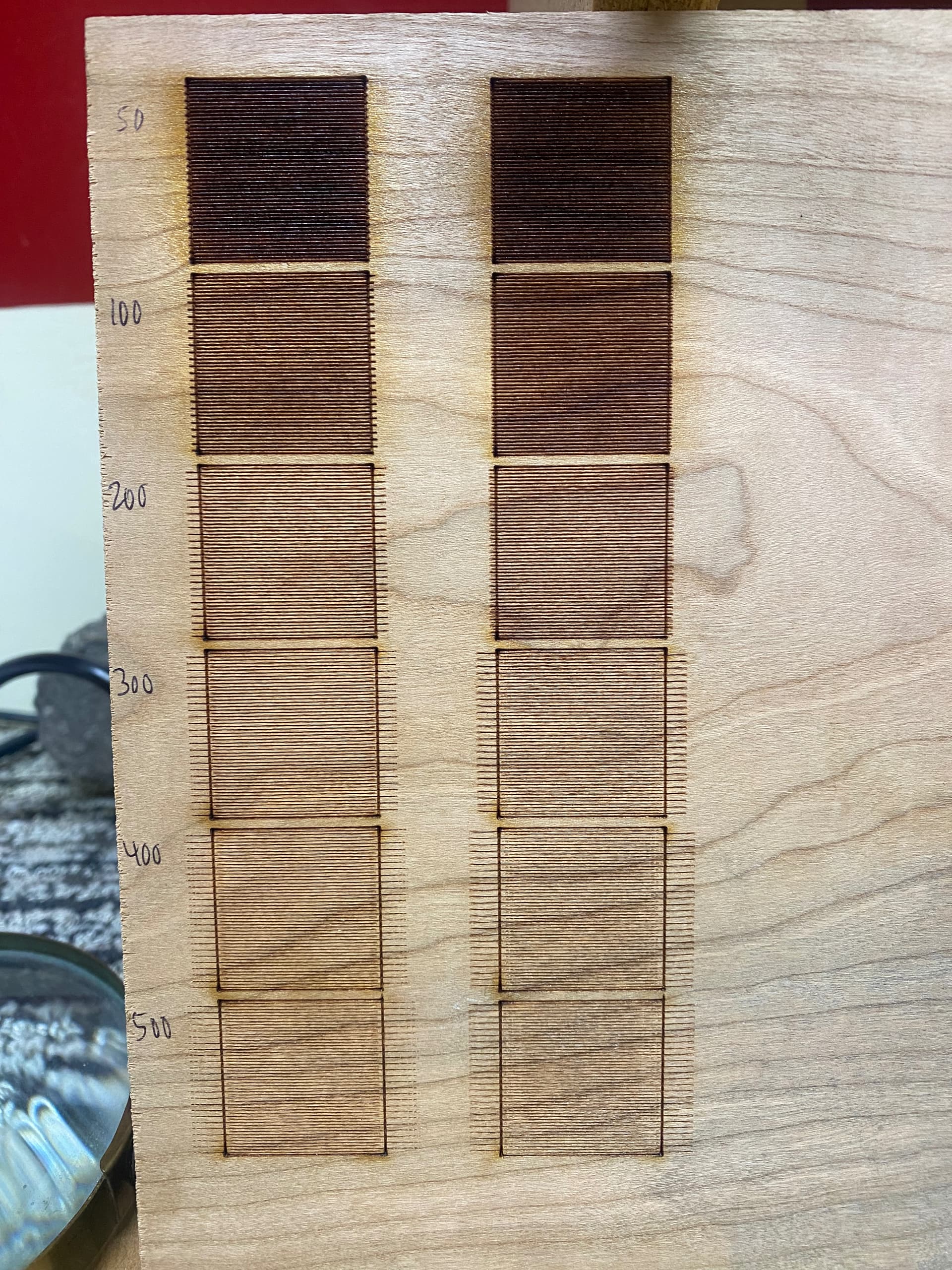
Measure the raw offsets with the adjustment disabled at 50, 100, 200, 300, 400, and 500 mm/s, put half the measured values into the table, enable the adjustment, and run the same tests again. Upload pix of the results along with a screenshot of the table so we can look over your shoulder.
Perhaps comparing pictures of the results you get with those from a good tube will help:

Those are 40 ms pulses at 25% of a 60 W tube on cardstock (manila file folder) and show what the beam should look like. Ideally, the scorch should be darker in the center, but paper doesn’t have a lot of dynamic range.
I’d be surprised if any tube failed their test, because the shape of that pit depends more on the dynamics of vaporizing acrylic than fine details of the beam shape. But my surprise absolutely does not matter if that’s the result they want … ![]()