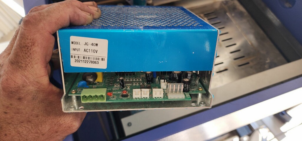
i have upgraded my omtec 40w machine to a 100watt tube and a cloudray 100 watt pw supply and now only the laser works. the lights dont come on int back like usual no homing nothing. alarm lock and homing fail is what im getting,is it a software/driver issue or is it a wiring issue
Was this a K40 type machine? And you managed to shoehorn a 100W tube in it? Interesting… like to see a photo… ![]()
Can you talk to the controller with lightburn?
If you changed the wiring, I’d say you broke it… it’s not software … that doesn’t break, bugs maybe.
Regurgitate to us what you changed in the upgrade and what controller is currently in it… did you change the controller out?
How is the controller wired to the machine.
How do you know that only the laser works?
Will it lase from the software or are you pressing what button?
![]()
ok i try and attach pics and i will do my best to answer all your question thanks for responding
No problem, we’d like to get you up and running, but you gave us little to work with…
![]()
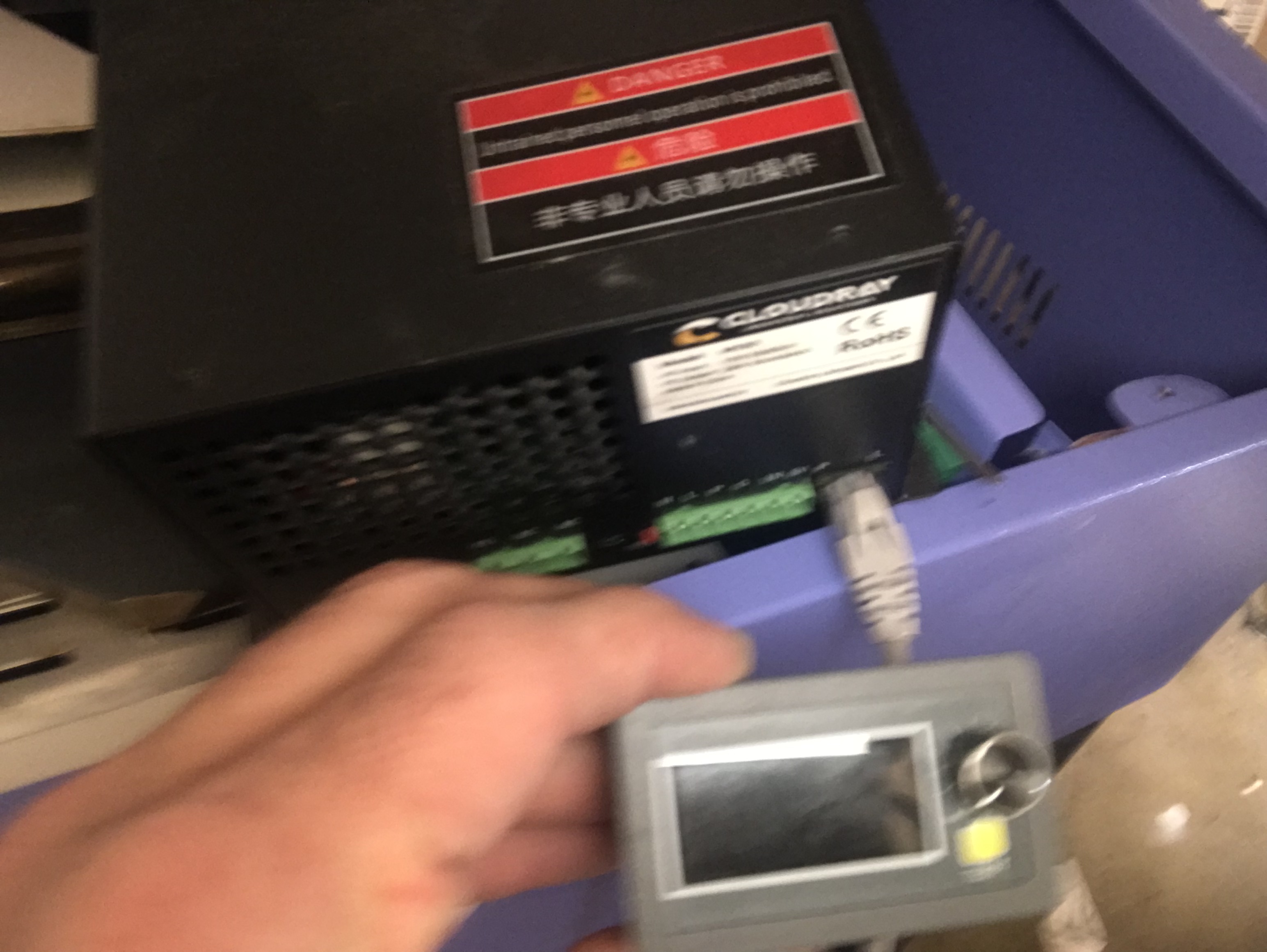
. so the bulb or pw supply went out and i decided to as you would say shoe horned a 100 w tube into it. I removed the old power supply and followed the wire diagram or lack of one and now the machine only fires the laser and only manually. i think its a driver issue cause i have not done any downloading or installing cause im unsure of what to download. cloud ray wont deal with me cause i got it from amazon, the myjg100 with lcd display…Pc is a windows 10
having trouble with the pics but i will figure it out
Do you have a pinout of the control board…?
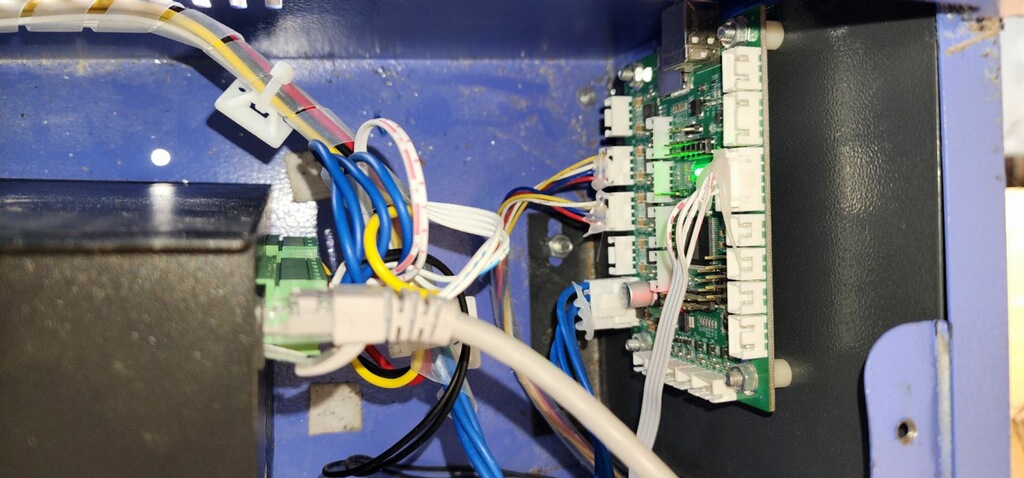
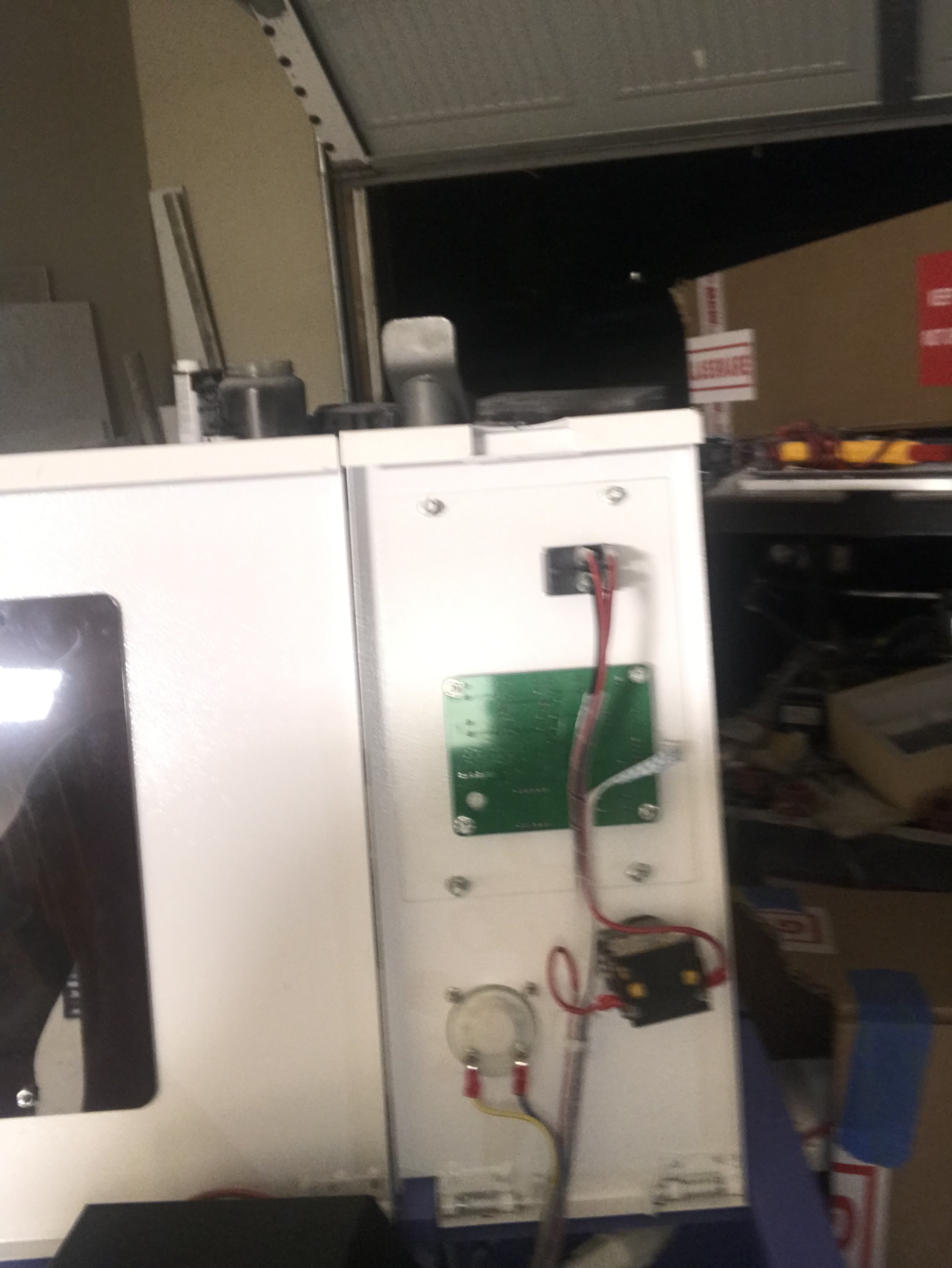
I can’t tell how you wired the lps (laser power supply) from the photo…
Can you supply me with what you have for pinout of the control board?
I doubt there is a driver issue between the board and laser… unless you mean that Lightburn isn’t talking to it.?
- Which control board do you have?
- does lightburn talk to it?
- do you have a pinout of how it connects to the lps?
![]()
Ok i just got up and seen your request, on it.
ok, they are comunicating, at least i believe they are simply because i tell it to home from lightburn and it knows it didnt home. im getting all info on where my wires are landed and labeling for you right now cause its wrong somewhere.

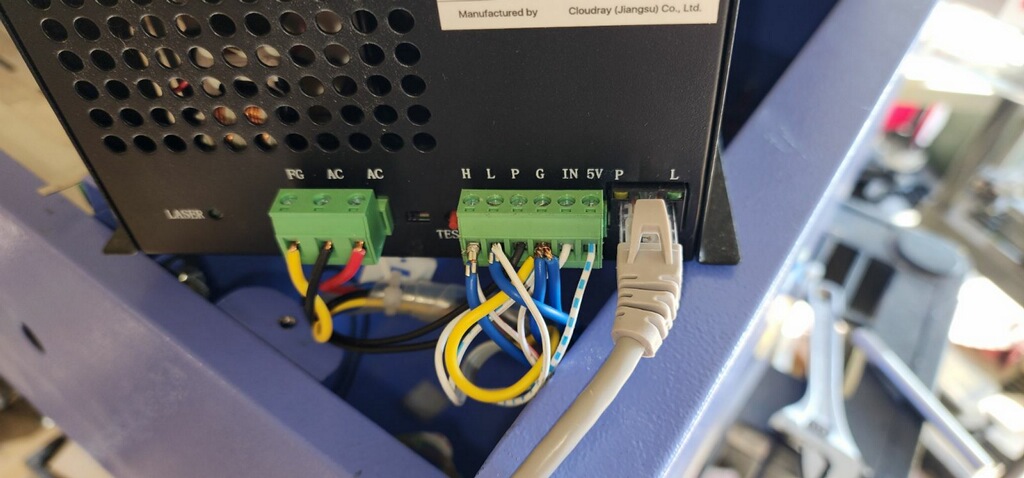
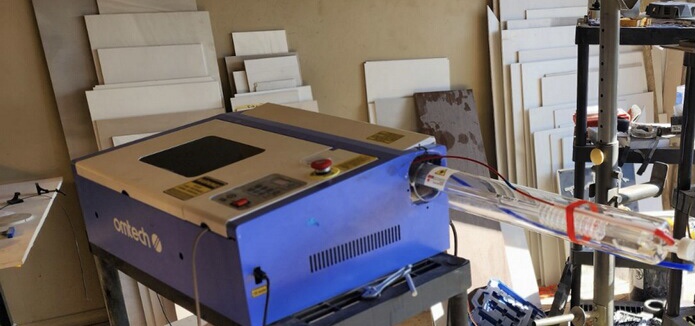
You’ve gone through lots of effort, but I can read the lps connections, but have no idea where you have them wired…
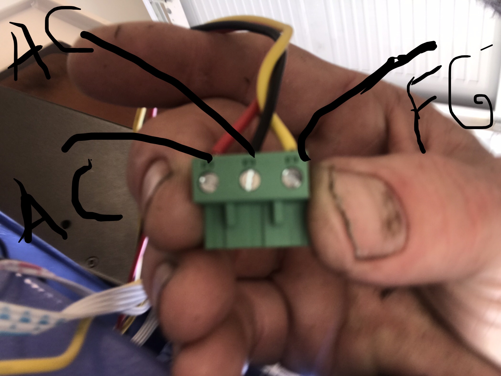
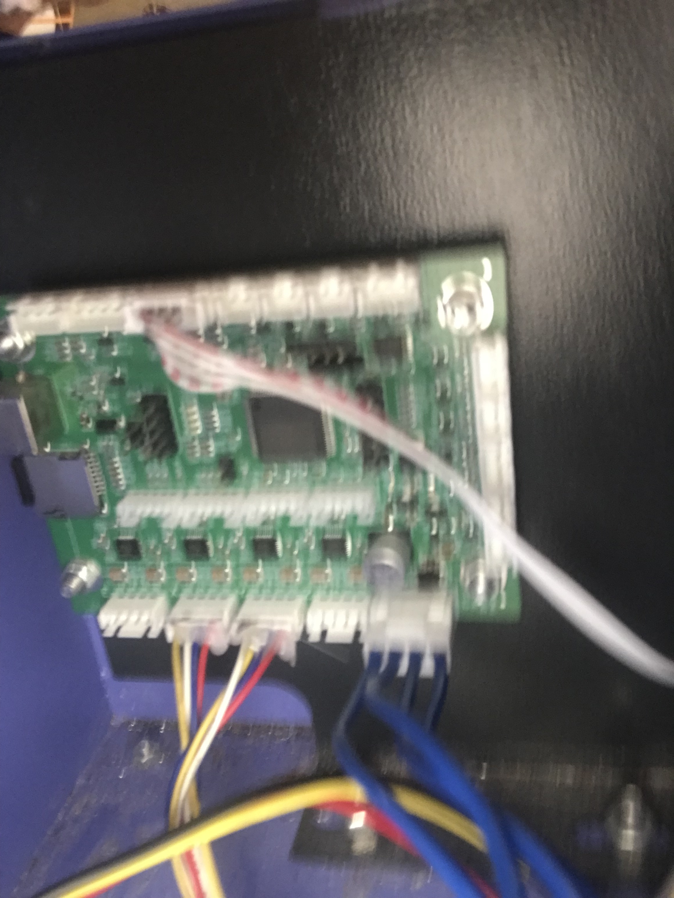
Chase down where the L, P, G and PWM or IN goes into the controller…
From what I can tell, it’s plug and play…
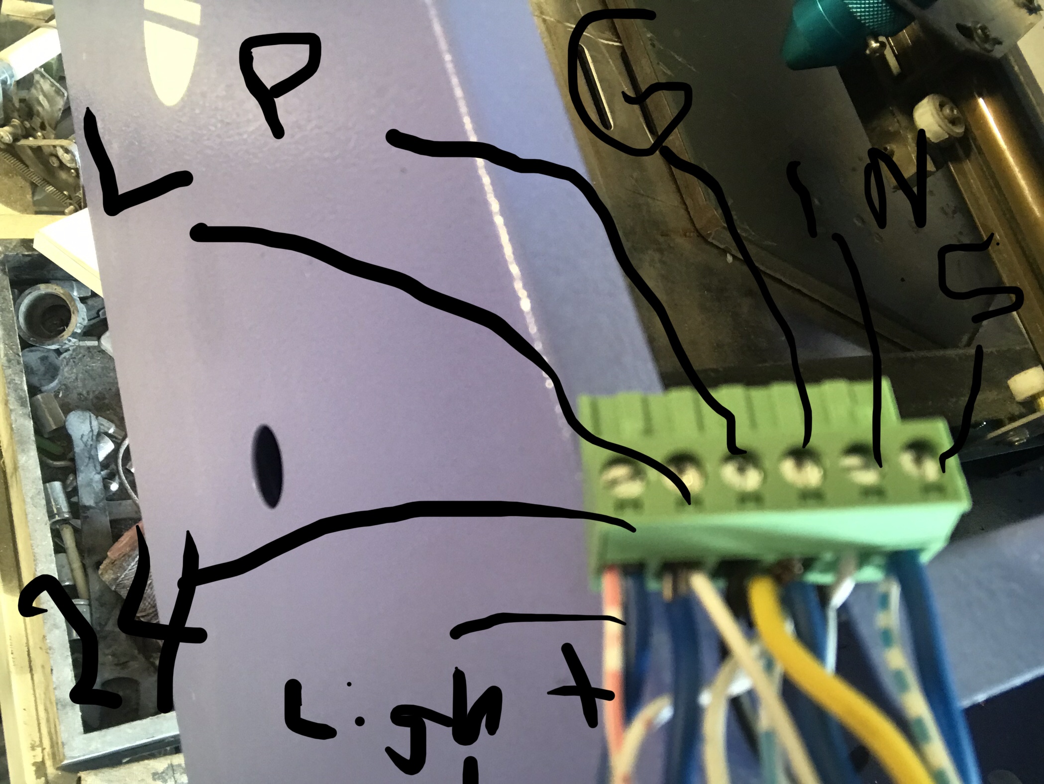
You need to finish wiring it up… you only have the limit/home switches and the pair of motors connected…
There is little (more like nothing) on how this plugs into a different lps.
You might have to follow it to the original lps and translate the signal to the replacement lps.
I have another place to check…
![]()
1 Like
well thats one issue i guess i have the in going into the the stock power display, so the in is not even going to the motherboard. the p and the g are going to my limit/safety switch on the lid of the machine. i dont have a pulse width modulator plug in that i know of.
Most of these hook up a bit differently than the dsp type controllers.
If you have a pot (or digital) adjustment on your machine, the IN terminal of the lps may be wired there for a dc voltage so you can control power at the machine.
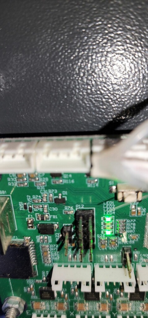
Looking back at the first photo, it looks like it right under the emergency power off switch.
Somewhere there is a pwm control and many times that goes to the L (or more likely the H, which is active high) This is the laser enable control. When this becomes active, the tube should lase at the current set at the IN terminals…
Make sense?
![]()
all i see is or think of is that the lightburn sends out the directions to the machine and it either isnt recieving the signals or it isnt understanding them not sure though im not the best electric trouble shooter I appreciate you hanging in there with me though cause this is oh so frustrationg knowing that its probably extremely east to fix and staring down and yet im missing it
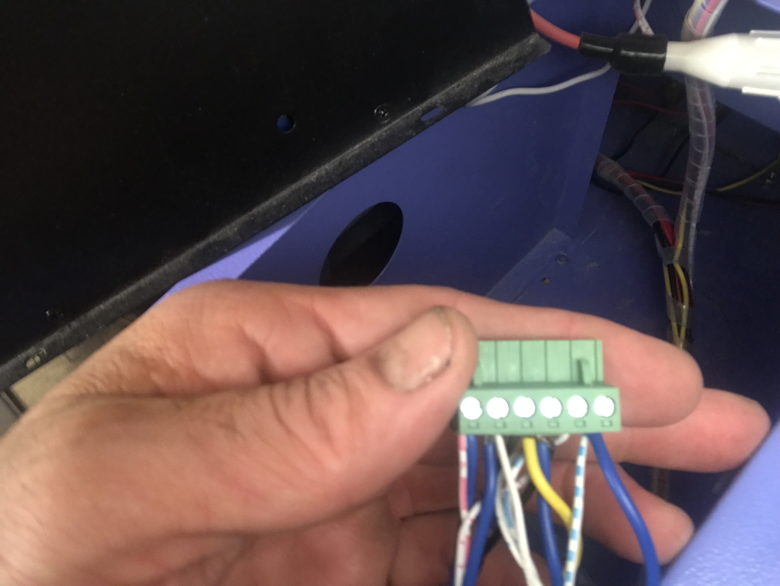
You’re still missing wires off the controller…
Pictures of connectors with wires hanging out of them is of little use to us. Color don’t mean anything on these, so I need to know how the lps is being driven off the new board… I see no connections on your board for the lps. You have wires running to them, but from where?
I’ve browsed through the documentation on the board and its supposed to be a plug and play change out.
There is nothing there that shows actual connection to the lps.
If you have a control of some type that plugs into the lps Ethernet type connector, I don’t know how that works.
I was speaking about the console 0 to 10 adjustment being wired to IN…
Do you have a photo, that’s legible of the original board?
![]()
I apologize if I am wearing you thin.
I just checked my cloud ray power supply for voltage on the h and I’m getting 0 isn’t that supposed to be 24 volts coming from there. I can’t find original motherboard,
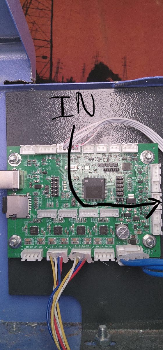
In the pic I sent of my current motherboard I found where the in connection is and nothing is connected there. It should be connected to the power supply in slot right?
Looks to me like the power is to the bottom right…?
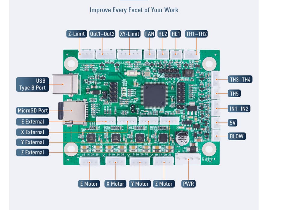
Have you looked here to determine which pins you will need?
![]()
1 Like