Yes it is.
man i just cant figure this out
You may have taken a rather large byte ![]()
I think it would have been better to change one at a time and ensure the controller works with the original lps and tube.
Then it would have been more simple to debug less of an issue.
In your position I’d email OMTech and ask them for information on wiring up their board with one of the non K40 type lps that you have installed.
Their pdf is more than lacking in information for the laser user… I don’t think they deal with milling or other machines and the pdf is a general guide to those controllers. With a few pictures of how it’s wired … mostly just changing connectors.
There are only a few things you need ask OMTech… which pin is the pwm output and if there is a laser enable output, which I doubt…
They must have this documented somewhere as people use different lps in lots of cases…
The manual is there as is the link to the configuration.
It specifies…
laser_module_pwm_pin                          2.5              # this pin will be PWMed to control the laser. Only P2.0 - P2.5
                                                              # can be used since laser requires hardware PWM
Is your pwm pin, but don’t know how 2.5 relates to the motherboard…
There is an example of a board and lps… doesn’t look like your board.
I think it would be to your advantage to ask OMTech for information such as the pwm output pin location.
At the very least you should be able to move the machine around with Lightburn…
![]()
right on, thanks
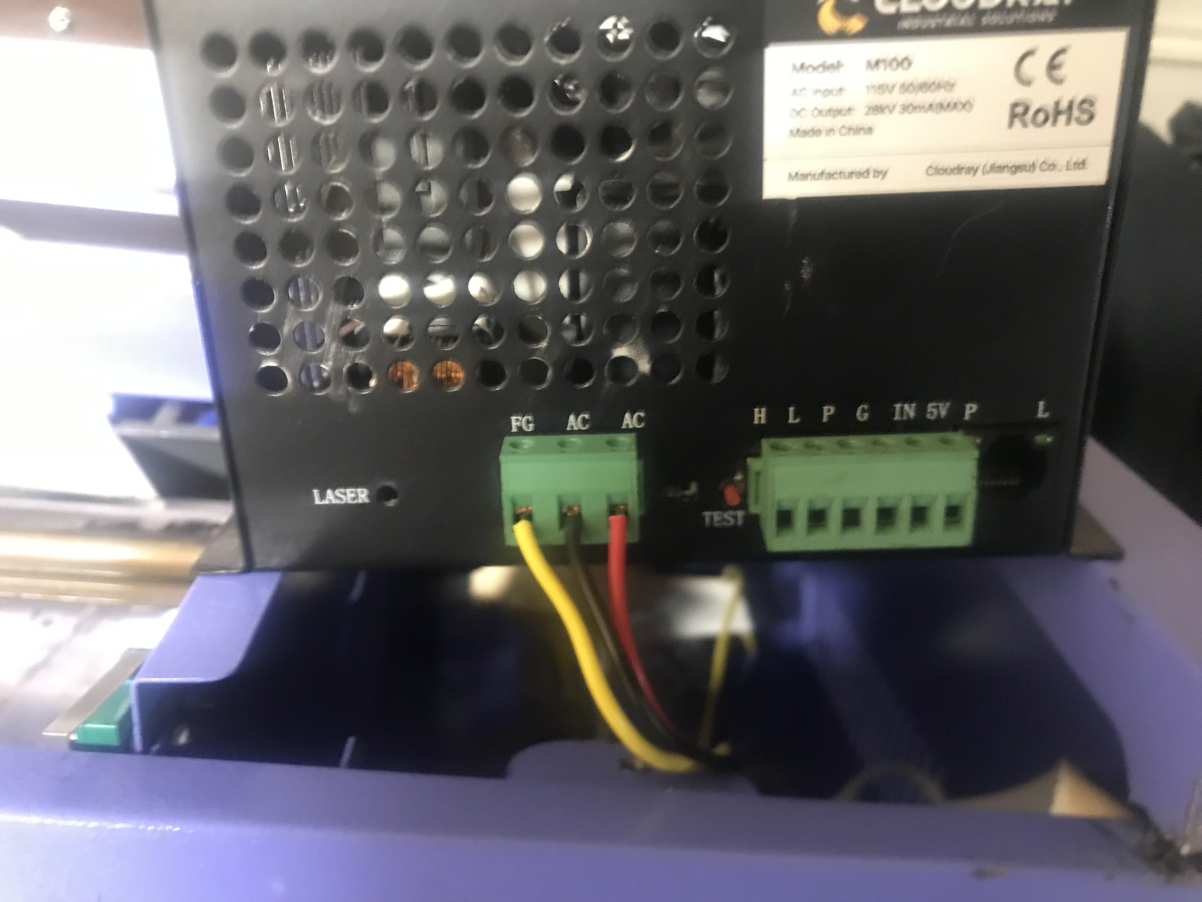
I don’t see a 24V power supply that takes the AC line power and converts it to run the stepper motors.
I see the white plug(below). Which end is that and what does it plug into?
This (above) looks right. I’d need to see it plugged in to be sure.
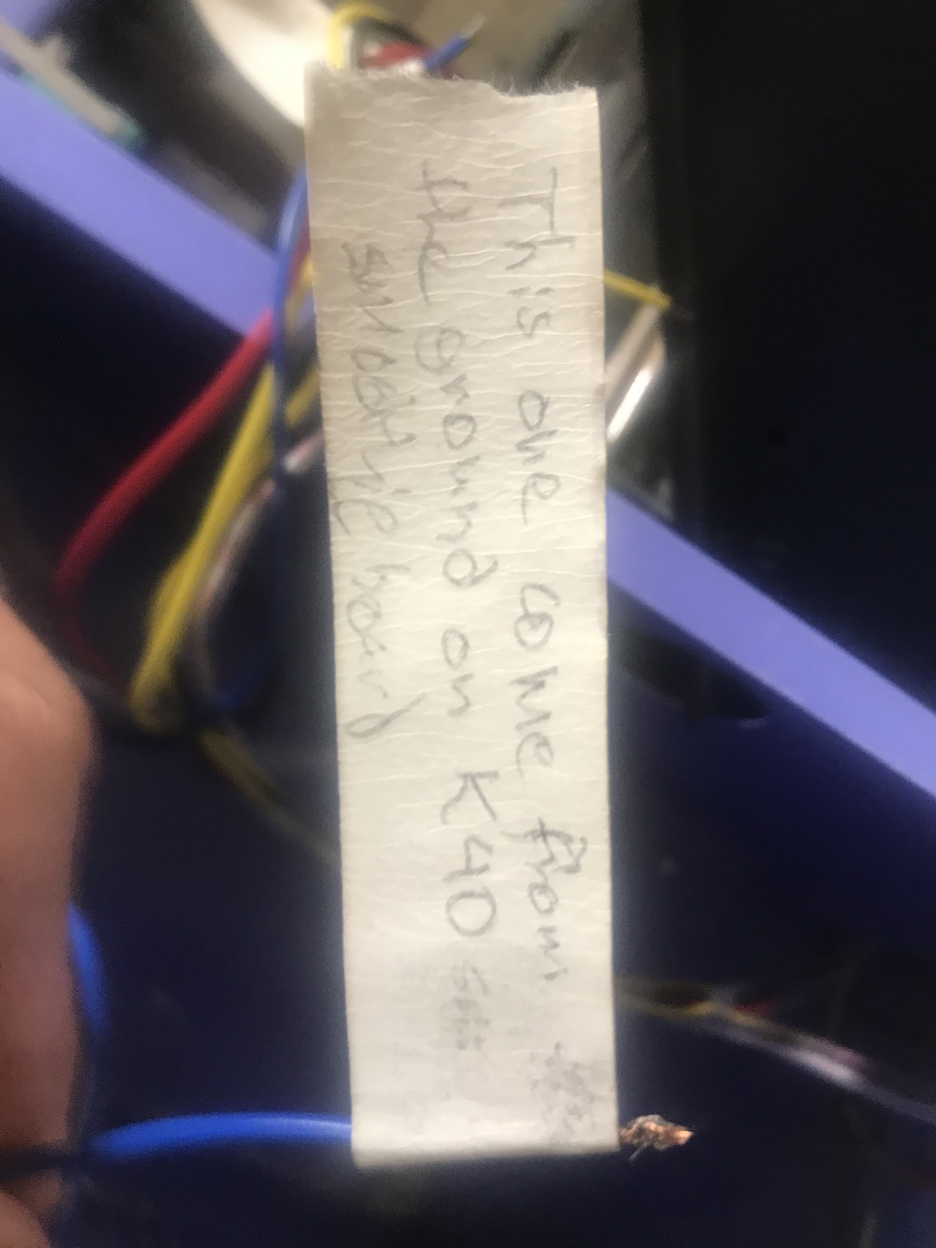
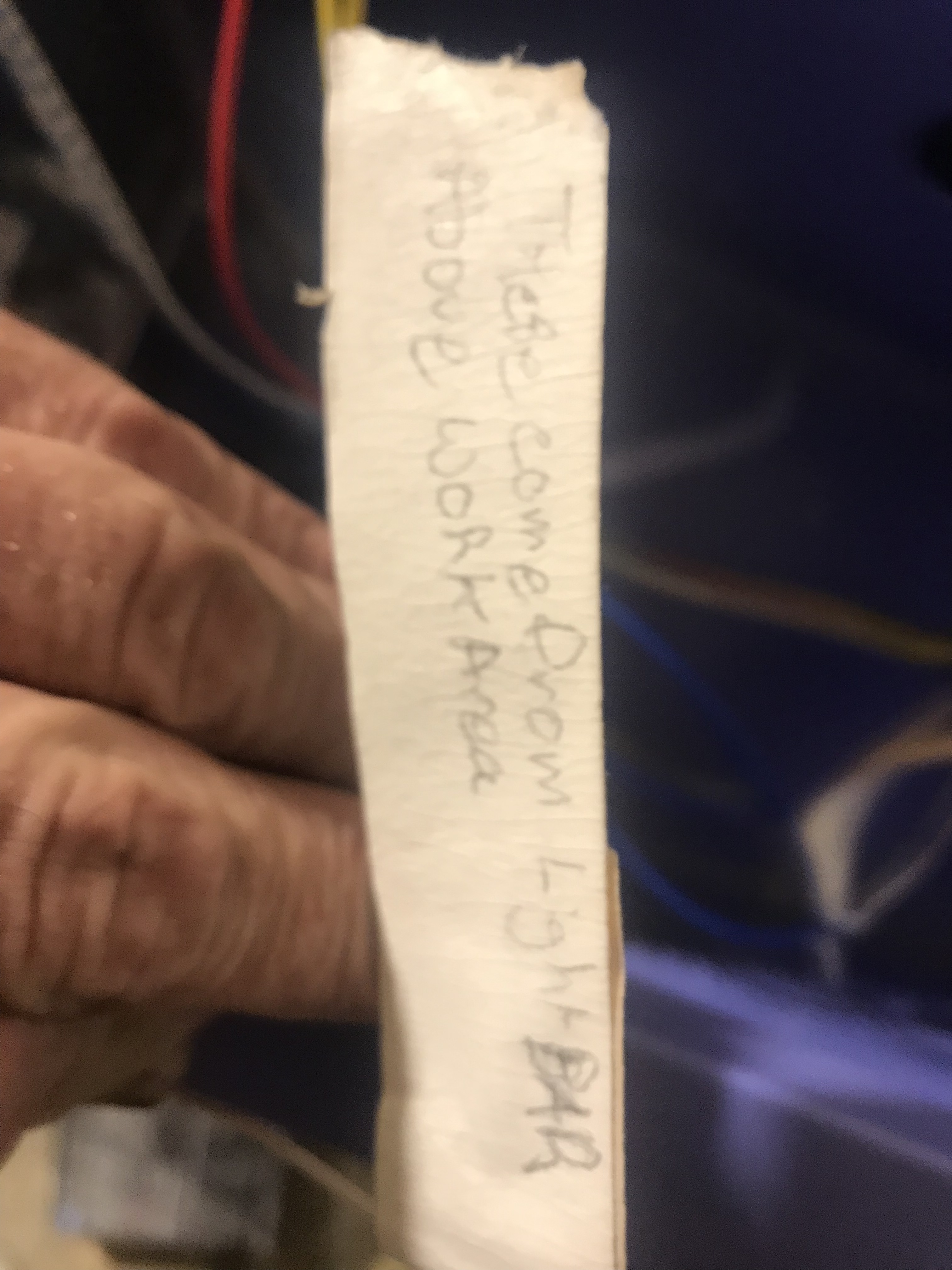
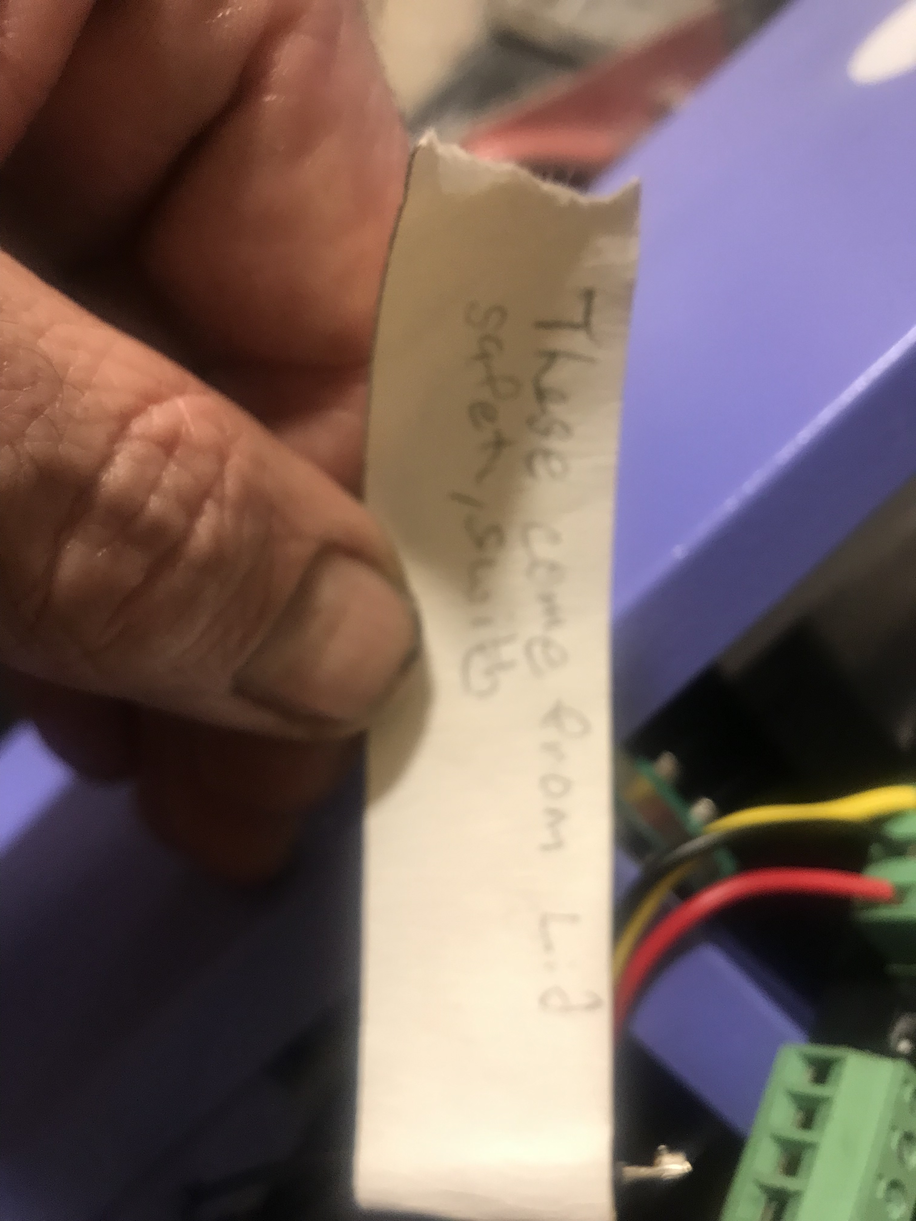
This one (above) scares me lots.
Starting left to right, where do the wires go.
Screw terminal #1
Pink / white
dark blue
Screw terminal #2
dark blue
skinny white
Screw terminal #3
Black
Yellow
Screw terminal #4
Dark Blue
Maybe something else…?
Screw terminal #5
Skinny white wire
Screw Terminal #6
Dark Blue
blue/white
If the wires go to the controller, it may be of great help to use these words to tell us where they go.
power supply, different voltage output reversed dc polarity maybe

You asked about a 24v power supply for the steppers and I didn’t know it needed one but fortunately I have one and I took a pic of it for you.
This was a bad idea, especially if the photo is how they are labeled…
Don’t disassemble things, it just adds more potential issues to a possible fix.
There is no advantage in removing wires from the connector… just increases the chances of a miswire when it’s reassembled…
I think there is a misunderstanding on what we need from you and what you think we are asking for. I do have faith that you can make it work, but you are in for a very steep learning curve.
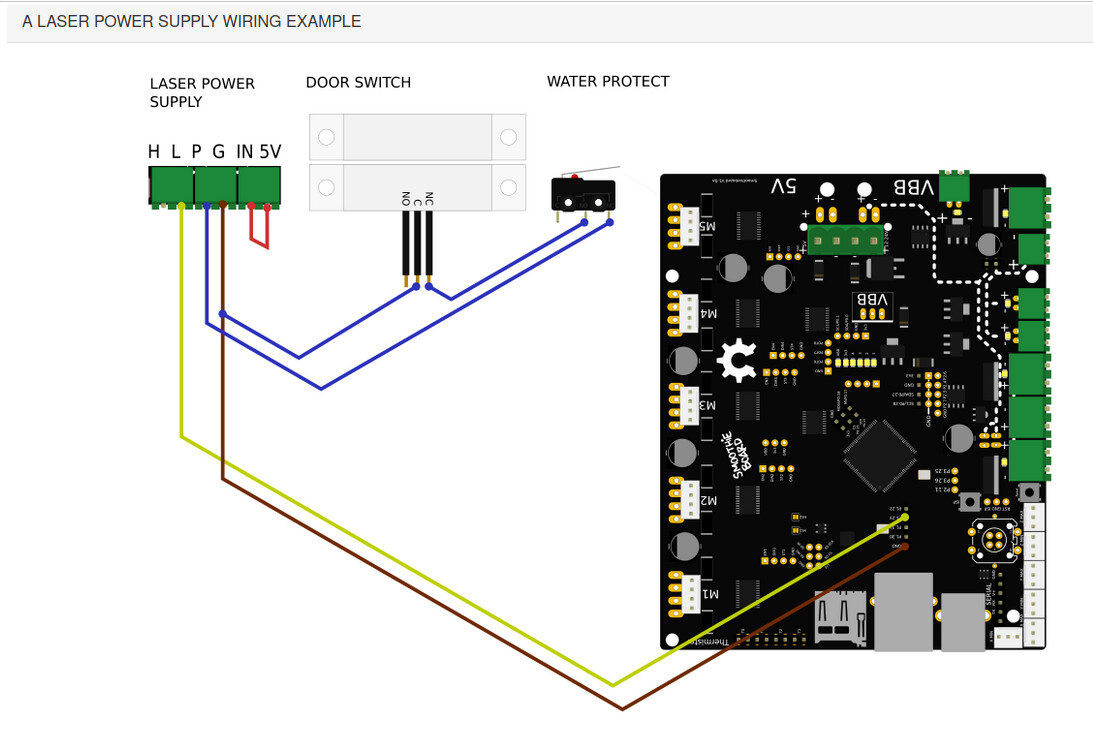
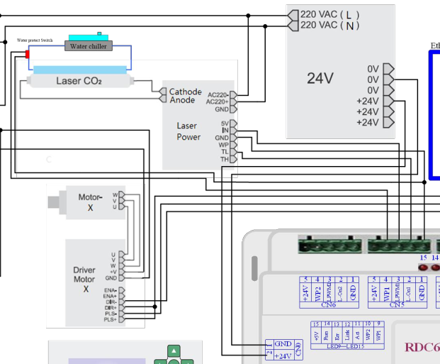
We need more specifics of how it’s interconnected. Most of us call them schematics… Look at post 23 where both ends of the connections to the lps and controller are shown along with identified signal names. This clearly shows what wire goes where… color doesn’t matter as it may change depending on what wire they have…
This allows us to quickly and clearly see how it’s wired and can spot problems with wiring in a short amount of time…
We need something similar to this for your wiring. I’m not asking for this type of comprehensive guide, even a hand drawn one would be good.
This is a portion of a proper schematic for a controller. It shows the wiring for a more expensive dsp controller… the type of controller is irrelevant, but the control signals are most relevant. It clearly shows how to connect the controller to an lps.
As far as I can tell you do not have a mA meter in the common thought we use here … I assume this be the dc voltage control board on the machines console…?
Have you had contact with OMTech about your boards wiring? The pdf they have is clearly for a 3d printer or something similar… few lasers use a heated table that need temperature sensors. Names like HE1 and HE2 usually refer to heat control for 3d printers…
The signal names you need are not even mentioned in any of the documentation… You should query OMTech about that… I think you should ask them how to wire the new lps with their board.
This is the last photo of the board installed… The red arrow are the bolt holes…
In it, I can see the x and y motor drivers, power and the home/limit switches, but cannot see any indication of any wires to the lps.
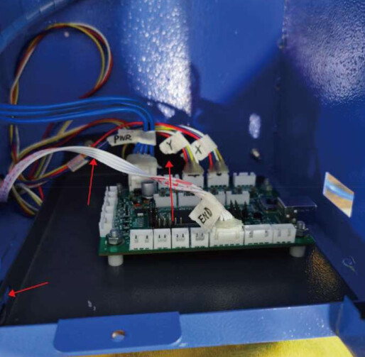
In simple terms there is no way to wire this up if you don’t know where the pwm and other control signals originate from the control board. OMTech needs to advise you on how to connect it to your specific lps.
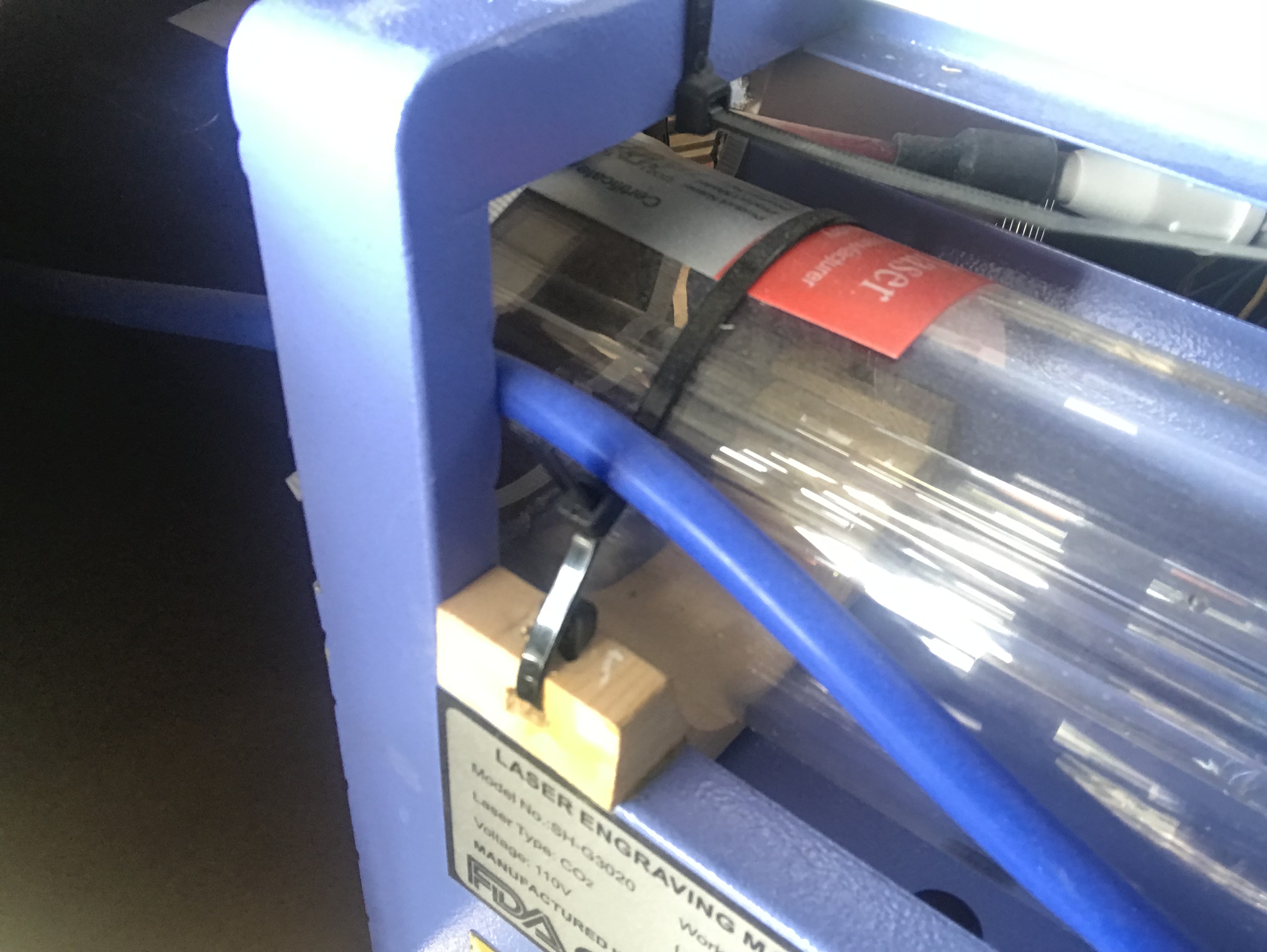
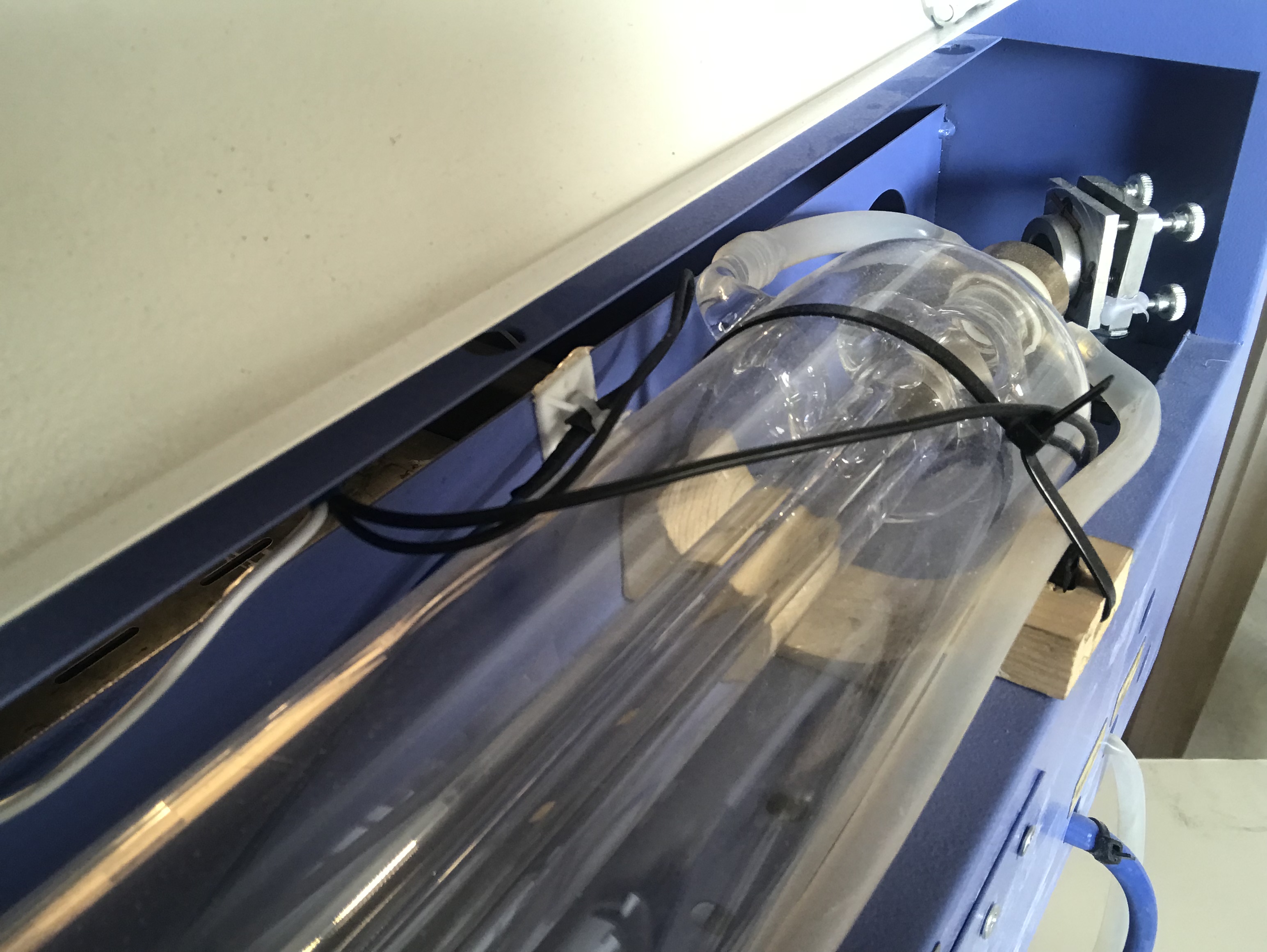
I have had this burning question about how you managed to get that huge tube lined up, optically, in that little machine? ![]()
How did you deal with the difference in diameter?
Did you find some kind of mount that allowed you to lower the tube 15mm? Didn’t think there was that much free area between tube and cabinet to accomplish this.
If you didn’t lower the tube, conversely, I didn’t think there was enough room to raise m1 and m2 15mm… I know the head would require a new mount to move it in the Z direction that amount or any movement at all in that axes.
Good luck…
![]()
Man I’m not trying to make things any more difficult I just felt the need to clear everything up for myself and whoever was going to help me. This shouldn’t be happening to me because I just self taught myself how to program and design with my cnc machines on fusion 360 and it’s the hardest of Learning curves in my opinion but I didn’t begin to understand until I learned the language and it’s meaning/definitions it took me 3 weeks to break through but finally did and I just don’t want that to be what happens here. I’m confident that we w will figure it out, and modifications i had to fear were rather easy. You just have to fabricate the mounts yourself and make them short as you can either with your 3D printer or you make it super easy like me and cut them out of wood with a band saw.
Tell me this, cause this I believe is the Issue. I think I have to have a separate psu for the 24v cause Jon Jon mentioned it and I saw a complete build with a similar cloud ray and he clearly has one which lucky me I have one also at the ready.
Did your machine come with a 12V or 24V power supply?
The board requires 24V… likely because of the stepper motors… logic doesn’t require such voltages.
I would think you could use the one that came with the machine…
Do you have and can drive a voltmeter?
![]()
Yea it came with a 24 volt out I believe where as the one from cloud ray is all 5v or below I was thinking the H would be the 24v but it isn’t which is where our communication got so frustrating cause you kept mentioning lps and psu and Iwas getting confused and I still am at a loss on why they would not have a 24 volt coming off my cloud ray doesn’t make sense whatsoever. Yes I do have a fluke volt Mtr and I can use it decently I’m not a electrician though.
Pretty simply because it’s not a 24V supply, it’s a 30kV supply…
Most regular low voltage power supplies are just ps, laser power supplies are lps.
Use the one that came with the machine if it’s 24V and can supply the required current… which it probably can…
![]()
Yea that’s what I a going to try and figure out how to pull off after I have butchered alll my connectors.
Well I got it all wired up correctly with a 24v psu and I still have nothing which makes me think my configuration file is wrong. Or I’m not sure because it’s not supposed to require a driver because of my operating system being win10 I don’t know.
Does Windows make any sound when you plug it in? Usually it means it’s connected…
Can you see the new board in the Windows device manager for usb?
If not, it’s likely a driver issue…
![]()